Kolpin 2623 Installation Instructions Manual
- Taper
- Installation Instructions Manual

2623 - Instructions POLARIS RANGER XP900 Full Tilt One Piece Ws - rev01 WWW.KOLPIN.COM
1
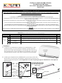
INSTALLATION INSTRUCTIONS
POLARIS RANGER XP900
FULL TILT ONE PIECE WINDSHIELD
PART # 2623
IMPORTANT NOTICES
READ AND UNDERSTAND THESE INSTRUCTIONS COMPLETELY BEFORE INSTALLATION TO AVOID INJURY TO YOURSELF,
DAMAGE TO THE VEHICLE OR ACCESSORY.
• FOR PROPER INSTALLATION, TWO PEOPLE ARE REQUIRED.
• TORQUE SPECIFICATIONS MUST BE FOLLOWED WHEN TIGHTENING BOLTS.
• AS SPECIFIED ON CARTON LABEL, ONCE PROTECTIVE FILM ON SHIELDS IS REMOVED, PRODUCT CANNOT BE RETURNED.
• AS SPECIFIED ON CARTON LABEL, DAMAGE CAUSED BY PACKAGING STAPLES IS NOT COVERED BY WARRANTY. ALL STAPLES MUST BE REMOVED PRIOR TO
REMOVING PRODUCT FROM CARTON.
• FAILURE TO FOLLOW THESE INSTALLATION INSTRUCTIONS COMPLETELY MAY VOID ANY WARRANTABLE COMPONENTS AND RESULT IN PRODUCT DAMAGE
OR PERSONAL INJURY.
• DO NOT USE LOCKTITE OR ANY OTHER SIMILAR FASTENER ADHESIVE. THESE TYPES OF PRODUCTS REACT TO PLASTICS AND CAUSE CRACKING. NOT
COVERED BY WARRANTY.
• OUR WINDSHIELDS ARE MADE FROM THE HIGHEST QUALITY MATERIAL PROVIDING OPTIMUM TRANSPARENCY AND CLARITY. BLURRINESS AND/OR
EXTRUSION MARKS MAY OR MAY NOT APPEAR WHEN LOOKING THROUGH WINDSHIELD FROM A WIDE, SIDE-ANGLE. THIS IS NORMAL FOR ALL EXTRUDED
CLEAR PLASTIC MATERIALS.
DEALER
These instructions contain important information for future reference and must be given to the customer at time of purchase or upon completion
of installation.
Parts List (parts available with kit only and not available separately)
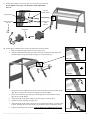
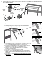
1. Installation
a) To apply the co-extruded bulb seal (Item B) to the windshield (Item A), find a
clean flat area where you can lay down the windshield. Partially remove the
protective film on both sides and apply the co-extruded bulb seal to the lower lip
using manual pressure to ensure good adhesion to the windshield. (The seal has
an internal steel wire structure, a wire cutter is required to cut the extra length)
b) To attach pivot components to the windshield (Item A), as per step a), find a clean
flat area where you can lay down the windshield. Partially remove the protective film where components (Item E & F) are to be
attached and follow drawings below. Do not tighten the screws that are passing through the windshield, they will be tightened
later in step d).
ITEM
PART NAME
DESCRIPTION
QTY
A
Windshield
CNC windshield cut-out made of ¼" thick GE MR10 polycarbonate or equivalent
1
B
Co-extruded bulb seal (¼")
Includes : 54" of co-extruded bulb seal [end user to cut to exact length]
1
INSTRUCTION
BAG
C
W-type clamps set
Includes : 2 W-type clamps
2
D
Nuts & bolts
Includes : 4 socket cap screws M6 x 20, 6 locknuts M6, 10 button head screws M6 x 18, 8 internal lock
washers M6, 8 plastic shoulder washers M6, 4 button head screws M6 x 45 & 2 ‘T’ knobs M6 x 35
1
E
Top pivot hinge of upper
windshield
Includes : 2 x upper pivots & 4 x upper pivot cylinder adaptors
1
F
Slide arm and lower pivot of
upper windshield
Includes : 2 x slide arms 3 positions & 2 x lower pivot mounts
1
Co-extruded
bulb seal
Button head
screw
M6 x 18
Internal lock
washer M6
Shoulder
washer M6
Upper
pivot
Lower
pivot
Slide arm
Locknut M6
Upper details
Lower details
Lower details
Upper details
Do not over-tighten the screws
that combine the slide arms with
the lower pivots, those parts
need to swivel.

2623 - Instructions POLARIS RANGER XP900 Full Tilt One Piece Ws - rev01 WWW.KOLPIN.COM
2
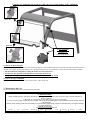
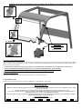
c) Attach clamps (Item C) to the roll cage of your vehicle as per drawings.
Do not tighten at this stage; you will need to make adjustments
later on.
d) Attach upper windshield to the machine by following instructions below.
1. Make sure that both upper clamps are at the same height.
2. Hold the windshield horizontally and slide it down by ensuring that both upper pivot
cylinder adaptors are going through the upper pivot as per drawing #1.
3. Pull gently on the windshield as per drawing #2 towards the front of the vehicle for the
upper pivot to slide to the end onto the upper pivot cylinder adaptor.
4. Lower the windshield as per drawing #3 and the upper pivot will catch the second
upper pivot cylinder adaptor.
5. Adjust the height of the upper clamp first by ensuring the overall leveling.
6. Tighten all screws regarding the upper pivot.
7. Adjust the height of the clamp to the lower pivot and slide arm and use ‘T’ knob to lock
in place. Drawing #4 shows the position you should have when windshield is closed.
8. Tighten all remaining screws and nuts with specified torque indicated on next page.
Locknut M6
W-type clamp
Top pivot
cylinder adaptor
Button head
screw
M6 x 45
Socket cap screw
M6 x 20
Locknut M6
Drawing #4
Drawing #1
Drawing #2
Drawing #3

2623 - Instructions POLARIS RANGER XP900 Full Tilt One Piece Ws - rev01 WWW.KOLPIN.COM
3
Caution: over tightening any hardware could cause irreversible damage to the windshield.
To operate the tilt mechanism:
Simply loosen both ‘T’ knobs (without removing them) and push on the windshield from the inside of the cab until the desired position is
reached. Then tighten knobs. Note that there are 3 pre-determined positions on the slide arm; closed, half-opened and fully-extended.
• The tilt mechanism is designed for cooling the airflow in warm temperatures.
• Note that any open positions are designed for low-speed operation ONLY.
• At high speed riding or when transporting the vehicle, the windshield must be closed.
To remove the upper windshield:
Remove both ‘T’ knobs and follow reverse instructions 4, 3 & 2 of step #d).
2. Maintenance and Care
Tighten all hardware after first use and periodically thereafter.
CLEANING:
Rinse with lukewarm water; wash gently with mild soap or detergent and lukewarm water, using a soft cloth or sponge. DO NOT SCRUB or use
brushes or squeegees.
Rinse again. Dry with soft cloth or moist cellulose sponge to prevent water spotting.
To remove wet paint, glazing compound or grease, rub lightly with a good grade of VM&P naphtha or isopropyl alcohol, then wash and rinse. DO NOT
USE GASOLINE.
NOTICE: Abusive cleaning procedures by hand washing or automated washing equipment will eventually result in visual hazing, loss of light transmission
and coating delamination.
Compatible Cleaning Agents
Aqueous Solution of Soaps and Detergents
- Fantastik1
- Joy2
- Neleco-Placer
- Hexcel, F.O. 554
- Windex5
- Formula 4091
- Lysol3
- Pine-Sol4
- Mr. Clean2
- Top Job2
IMPORTANT:
Torque specification
Max. 5 foot-pounds
Applicable to all
Clamp screws M6 x 20
Detail view
Detail view

2623 - Instructions POLARIS RANGER XP900 Full Tilt One Piece Ws - rev01 WWW.KOLPIN.COM
4
INSTRUCTIONS D’INSTALLATION
PARE-BRISE BASCULENT UNE PIÈCE POUR
POLARIS RANGER XP900
PART # 2623
NOTIFICATIONS IMPORTANTES
AFIN D’ÉLIMINER LES RISQUES DE BLESSURES ET LES POSSIBILITÉS D’ENDOMMAGER VOTRE VTT OU D’AUTRES
ACCESSOIRES, VEUILLEZ LIRE ATTENTIVEMENT LES INSTRUCTIONS SUIVANTES AU COMPLET AVANT DE D’ENTREPRENDRE
L’INSTALLATION.
• DEUX PERSONNES SONT NÉCESSAIRES POUR UNE INSTALLATION ADÉQUATE.
• TOUTES LES SPÉCIFICATIONS DE COUPLES DE SERRAGE DOIVENT ÊTRE RESPECTÉES.
• TEL QU’INDIQUÉ SUR L’EMBALLAGE DU PRODUIT, VOUS NE POUVEZ RETOURNER AUCUN PARE-BRISE DONT LA PELLICULE PROTECTRICE ORIGINALE A ÉTÉ
RETIRÉE.
• TEL QU’INDIQUÉ SUR LA BOITE DU PRODUIT, TOUT DOMAGE CAUSÉ PAR LES AGRAFFES DE L’EMBALLAGE NE SONT PAS COUVERT PAR LA GARANTIE. VOUS
DEVEZ AVOIR ENLEVÉ TOUTES LES AGRAFFES AVANT DE RETIRER LE PRODUIT DE SON EMBALLAGE.
• LE NON-RESPECT DES PROCÉDURES D’INSTALLATION PRÉCÉDENTES PEUT ENTRAÎNER L’ANNULATION DE LA GARANTIE SUR LES COMPOSANTES AINSI
QUE RISQUER D’ENDOMMAGER LE PRODUIT ET/OU DE VOUS BLESSER.
• NE PAS UTILISER D’ADHÉSIFS À BOULONNERIE TEI QUE LOCTITE OU AUTRES MARQUES. CES TYPES DE PRODUITS RÉAGISSENT AVEC LE PLASTIQUE ET
CAUSE DES FISSURES. NON COUVERT PAR LA GARANTIE.
• NOS PARE-BRISES SONT FABRIQUÉS AVEC DES MATÉRIAUX DE TRÈS HAUTE QUALITÉS ET OFFRENT UNE CLARITÉ ET UNE TRANSPARENCE OPTIMALES.
LORSQUE L’ON REGARDE UN PARE-BRISE D’UN ANGLE TRÈS LARGE, IL EST POSSIBLE ET NORMAL D’OBSERVER UNE DIMINUTION DE LA QUALITÉ OPTIQUE
COMME UNE VUE FLOU ET/OU DÉFORMÉE. CE PRÉNOMÈNE EST NORMAL ET RÉCURANT POUR TOUT LES TYPES DE PLASTIQUE EXTRUDÉ.
CONCESSIONNAIRE
Ces instructions contiennent des informations importantes. Vous devez les remettre à votre client au moment de l’achat ou dès que
l’installation est terminée.
Liste de pièces (pièces disponible seulement avec l’ensemble, non disponible séparément)
1. Installation
a) Trouvez un endroit propre ou vous pouvez déposer le pare-brise (Article A) sans
risquer de les endommager. Avec une extrême prudence, retirez partiellement la
pellicule protectrice nécessaire de chaque cotés pour insérer le joint de garniture à
bourrelet (Article B) tel qui indiqué sur l’image de droite en exerçant une pression
ferme sur toute sa longueur pour vous assurez d’un bon montage. (Pour couper
l’excédent du joint, vous devez utiliser un coupe-fil due à la structure interne
métallique du joint)
b) Avec une extrême prudence, retirez partiellement la pellicule protectrice
nécessaire de chaque cotés du pare-brise (Article A) pour fixez les pivots inférieurs et supérieurs (Article E & F) avec la quincaillerie
fournis (Article D) tel que montré ci-dessous. IMPORTANT: N’effectuez aucun serrage final sur les vis traversant le pare-brise à
cette étape. Elles doivent être serrées plus tard.
ARTICLE
NOM DE PIÈCE
DESCRIPTION
QTE
A
Pare-brise
Pare-brise de polycarbonate GE MR10 ¼" (ou équivalent) découpé au CNC
1
B
Joint de garniture à bourrelet (¼")
Comprends : 54" de joint de garniture à bourrelet [à tailler au moment de l’installation]
1
SAC
D’INSTRUCTION
C
Ensemble de brides (Type W)
Comprends : 2 brides (Type W)
2
D
Quincailleries de montage
Comprends : 4 vis à tête cylindrique M6 x 20, 6 écrous autobloquants M6, 10 vis à tête bombé M6 x 18, 8
rondelles frein M6, 8 rondelles d’épaulement M6, 4 vis à tête bombé M6 x 45 et 2 poignées en ‘T’ M6 x 35
1
E
Ensemble pivot supérieur
Comprends: 2 pivots supérieurs et 4 cylindres de pivot
1
F
Ensemble pivot inférieur
Comprends: 2 bras coulissants et 2 pivots inférieurs
1
Joint de garniture
à bourrelet
Vis à tête
bombé
M6 x 18
Rondelle
frein M6
Rondelle
d’épaulement M6
Pivot
supérieur
Pivot
inférieur
Bras coulissant
Écrou auto-
bloquant M6
Détails supérieurs
Détails inférieurs
Détails inférieurs
Détails supérieurs
Ne pas trop serrer les vis qui
combine les bras coulissants et
les pivots inférieurs, elles doivent
glisser une sur l’autre.

2623 - Instructions POLARIS RANGER XP900 Full Tilt One Piece Ws - rev01 WWW.KOLPIN.COM
5
c) Attachez les brides (article C) à la cage protectrice du véhicule comme indiqué ci-dessous. Ne pas serrer à cette étape, vous devrez
faire des ajustements plus tard.
d) Fixez le pare-brise au véhicule en suivant les instructions suivantes.
1. Assurez-vous que les 2 brides supérieures sont à la même hauteur.
2. Tenir le pare-brise en position horizontal et laissez le glisser vers le bas de façon à
insérer les pivots supérieurs sur les cylindres de pivot tel que montré sur l’image #1.
3. Tirez légèrement le pare-brise vers l’avant du véhicule tel que montré à l’image #2 pour
obtenir la position maximale des pivots supérieurs sur les cylindres de pivot.
4. En laissant le pare-brise descendre par son propre poids, les pivots supérieurs s’inséreront
automatiquement aux seconds cylindres de pivot tel que montré à l’image #3.
5. Si nécessaire, ajustez la hauteur des brides supérieures en vous assurant d’un
alignement le plus parfait possible.
6. Serrez toutes les vis concernant les brides et pivots supérieurs.
7. Si nécessaire, ajustez la hauteur des brides inférieures et fixez-y les bras coulissants à
l’aide des poignées ‘T’ fournies. L’image #4 montre la position voulue lorsque le pare-
brise est fermé.
8. Serrez toutes les vis restantes selon les spécifications de couple de serrage fournies à
la page suivante.
Écrou auto-bloquant M6
Bride (Type W)
Cylindre de
pivot supérieur
Vis à tête
bombé
M6 x 45
Vis à tête
cylindrique
M6 x 20
Écrou auto-
bloquant M6
Image #4
Image #1
Image #2
Image #3

2623 - Instructions POLARIS RANGER XP900 Full Tilt One Piece Ws - rev01 WWW.KOLPIN.COM
6
Attention: trop serrer la quincaillerie peut occasionner des dommages irréversibles au pare-brise.
Pour opérer le mécanisme basculant:
Desserrez légèrement les 2 poignées en ‘T’ (sans les retirer complètement) et poussez le pare-brise de l’intérieur du véhicule jusqu’à la position
désirée. Ensuite, resserrez les poignées. Prendre note qu’il y a déjà 3 positions prédéterminées sur les bras coulissants, position fermée, demi-
extension et extension maximale.
• Le mécanisme basculant a été conçu pour permettre une circulation d’air rafraichissante lors de température extérieur élevé.
• Notez que l’utilisation du mécanisme en position ouvert est pour une utilisation à basse vitesse seulement.
• Pour le remorquage et l’utilisation à haute vitesse, le mécanisme doit être en position fermé.
Pour retirer le pare-brise:
Retirez les 2 poignées en ‘T’ et suivez les instructions inverse 4, 3 & 2 de l’étape #d).
2. Entretien et soin
Serrez toutes les composantes après la première utilisation et périodiquement par la suite.
NETTOYAGE:
Rincez à l’eau tiède. En utilisant un linge doux ou une éponge, lavez avec un savon doux ou un détersif et de l’eau tiède. NE FROTTEZ PAS; n’utilisez
pas de brosse ou de racloir.
• Rincez de nouveau. Séchez avec un linge doux ou une éponge pour empêcher la formation de taches causées par l’eau.
Pour retirer de la peinture fraîche, de la graisse ou autres produits similaire, frotter légèrement avec de l’alcool isopropyl ou une bonne qualité de
naphta VM&P, ensuite lavez et rincez. N’UTILISEZ PAS D’ESSENCE.
NOTE: Tout abus de nettoyage, à la main ou par équipement automatique causera de la détérioration du produit, la perte de transmission de lumière et
jusqu’à la délaminnation du revêtement anti-abrasion.
Agents nettoyant compatibles
Solution Aqueuse de Savons et de Détersifs
- Fantastik1
- Joy2
- Neleco-Placer
- Hexcel, F.O. 554
- Windex5
- Formula 4091
- Lysol3
- Pine-Sol4
- Mr. Clean2
- Top Job2
IMPORTANT :
Spécification de serrage
Max. 5 pi.-lbs
Applicable à tous les vis
M6 x 20 pour brides
Vue détaillée
Vue détaillée
-
 1
1
-
 2
2
-
 3
3
-
 4
4
-
 5
5
-
 6
6


Kolpin 2623 Installation Instructions Manual
- Taper
- Installation Instructions Manual
dans d''autres langues
- English: Kolpin 2623
Documents connexes
Autres documents
-
HUANUO HNLS07S Guide d'installation
-
Polaris Victory Vegas Jackpot / Ness Signature Series Le manuel du propriétaire
-
-
Classic Accessories 18-156-010401-RT Mode d'emploi
-
Peg Perego JD Gator XUV 2014/2015 Manuel utilisateur
-
-
-
APRILIA MANA GT ABS - 2009 Manuel utilisateur
-
Magellan 800 Guide de démarrage rapide
-