

2

3
Il simbolo sul prodotto o sulla confezione indica che il prodotto non deve essere
considerato come un normale riuto domestico, ma deve essere portato nel punto
di raccolta appropriato per il riciclaggio di apparecchiature elettriche ed elettroni-
che. Provvedendo a smaltire questo prodotto in modo appropriato, si contribuisce
a evitare potenziali conseguenze negative per l’ambiente e per la salute, che po-
trebbero derivare da uno smaltimento inadeguato del prodotto. Per informazio-
ni più dettagliate sul riciclaggio di questo prodotto, contattare l’ucio comuna-
le, il servizio locale di smaltimento riuti o il negozio in cui è stato acquistato il
prodotto. Questo elettrodomestico è marcato conformemente alla Direttiva Eu-
ropea 2012/19/EC sui riuti da apparecchiature elettriche ed elettroniche (WEEE).
IT
The symbol on the product or on its packaging indicates that this product may not be
treated as household waste. Instead it shall be handed over to the applicable collection
point for the recycling of electrical and electronic equipment. By ensuring this product
is disposed of correctly, you will help prevent potential negative consequences for the
environment and human health, which could otherwise be caused by inappropriate
waste handling of this product. For more detailed information about recycling of this
product, please contact your local city oce, your household waste disposal service or
the shop where you purchased the product. This appliance is marked according to the
European directive 2012/19/EC on waste electrical and electronic equipment (WEEE).
GB
Le symbole sur le produit ou son emballage indique que ce produit ne peut être traité
comme déchet ménager. Il doit plutôt être remis au point de ramassage concerné, se
chargeant du recyclage du matériel électrique et électronique. En vous assurant que
ce produit est éliminé correctement, vous favorisez la prévention des conséquences
négatives pour l’environnement et la santé humaine qui, sinon, seraient le résultat
d’un traitement inapproprié des déchets de ce produit. Pour obtenir plus de détails sur
le recyclage de ce produit, veuillez prendre contact avec le bureau municipal de votre
région, votre service d’élimination des déchets ménagers ou le magasin où vous avez
acheté le produit. Cet appareil est commercialisé en accord avec la directive européen-
ne 2012/19/EC sur les dèchets del équipments èlectriques et èlctroniques (WEEE).
F
El símbolo en el producto o en su embalaje indica que este producto no se pue-
de tratar como desperdicios normales del hogar. Este producto se debe entregar al
punto de recolección de equipos eléctricos y electrónicos para reciclaje. Al asegurar-
se de que este producto se deseche correctamente, usted ayudará a evitar posibles
consecuencias negativas para el ambiente y la salud pública, lo cual podría ocurrir
si este producto no se manipula de forma adecuada. Para obtener información más
detallada sobre el reciclaje de este producto, póngase en contacto con la admini-
stración de su ciudad, con su servicio de desechos del hogar o con la tienda donde
compró el producto. Este electrodomestico està marcado conforme a la directiva Eu-
ropea 2012/19/EC sobre los residuos de aparatos elèctricos y electrònicos (WEEE).
E

4
Das Symbol auf dem Produkt oder seiner Verpackung weist darauf hin, dass dieses
Produkt nicht als normaler Haushaltsabfall zu behandeln ist, sondern an einem Sam-
melpunkt für das Recycling von elektrischen und elektronischen Geräten abgegeben
werden muss. Durch Ihren Beitrag zum korrekten Entsorgen dieses Produkts schützen
Sie die Umwelt und die Gesundheit Ihrer Mitmenschen. Umwelt und Gesundheit wer-
den durch falsches Entsorgen gefährdet. Weitere Informationen über das Recycling
dieses Produkts erhalten Sie von Ihrem Rathaus, Ihrer Müllabfuhr oder dem Geschäft,
in dem Sie das Produkt gekauft haben. Dieses Elektrohaushaltsgerät ist entspre-
chend der EU-Richtlinie 2012/19/EC Über Elektro- und Elektronik – Altgeräte (WEEE).
D
Het symbool op het product of op de verpakking wijst erop dat dit product niet
als huishoudafval mag worden behandeld. Het moet echter naar een plaats wor-
den gebracht waar elektrische en elektronische apparatuur wordt gerecycled. Als
u ervoor zorgt dat dit product op de correcte manier wordt verwijderd, voorkomt
u mogelijk voor mens en milieu negatieve gevolgen die zich zouden kunnen vo-
ordoen in geval van verkeerde afvalbehandeling. Voor meer details in verband
met het recyclen van dit product, neemt u het best contact op met de gemeente-
lijke instanties, het bedrijf of de dienst belast met de verwijdering van huishou-
dafval of de winkel waar u het product hebt gekocht. Dit apparrat voldoet aan de
Europese richtlijnen 2012/19/EC voor elektrische en elektronische afval (WEEE).
NL

INDICE
Avvertenze
Versioni d’uso
Installazione
Funzionamento
Manutenzione
5
IT

6
AVVERTENZE
* I bambini e le persone inesperte o i disabili
possono utilizzare l’apparecchio solo sotto la
supervisione di adulti.
* La distanza minima tra la supercie del piano
di cottura e la parte inferiore della cappa deve
essere pari a 650 mm.
* L’aria raccolta non deve essere convogliata
in un condotto usato per lo scarico di fumi di
apparecchi alimentati con energia diversa da
quella elettrica(impianti di riscaldamento cen-
tralizzati, termosifoni, scaldabagni, ecc.).
* Nell’operazione di collegamento elettrico
assicurarsi che la presa di corrente sia munita
di collegamento a terra e vericare che i valori
di tensione corrispondono con quelli indicati
nella targhetta all’interno dell’apparecchio.
* Prima di procedere a qualsiasi operazione di
pulizia o manutenzione è necessario togliere
l’apparecchio dalla rete.
Se l’apparecchio non è provvisto di cavo essi-
bile non separabile e di spina, o di altro dispo-
sitivo che assicuri la omnipolare disinserzione
dalla rete, con una distanza di apertura dei
contatti di almeno 3 mm, allora tali dispositivi
di separazione dalla rete devono essere previ-
sti nell’installazione ssa.
Se l’apparecchio è provvisto di cavo alimen-
tazione e di spina, deve essere posto in modo
che la spina sia facilmente accessibile.
Evitare l’uso di materiali che causano amma-
te (ambè) nelle immediate vicinanze dell’ap-
parecchio.
Nel caso di fritture fare particolarmente atten-
zione al pericolo di incendio che costituiscono
olio e grassi.
Particolarmente pericoloso per la sua inam-
mabilità è l’olio già usato. Non usare griglie
elettriche scoperte.
Per evitare un possibile rischio di incendio at-
tenersi alle istruzioni indicate per la pulizia dei
ltri antigrasso e la rimozione di eventuali de-
positi di grasso sull’apparecchio.
VERSIONI D’USO
L’apparecchio può essere utilizzato solo in
versione ltrante.
Nella versione ltrante l’aria ed i vapori con-
vogliati dall’apparecchio, vengono depurati
da un ltro antigrasso, da un ltro al carbone
e rimessi in circolazione nell’ambiente.
Il ltro carbone è in dotazione con la cappa.

7
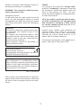
INSTALLAZIONE
Vericare che tutti i componenti non siano
danneggiati, in caso contrario contattare il
rivenditore e non proseguire con l’installa-
zione.
La ditta produttrice non risponde per danni
causati durante la movimentazione e l’instal-
lazione del prodotto.
Prima di procedere all’installazione leggere
attentamente tutte le istruzioni di se-guito
riportate.
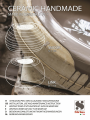
ATTENZIONE: Questo prodotto è realizzato
in ceramica e necessita pertanto di una ac-
curata e attenta movimentazione, come pure
di una professionale e diligente installazione.
Utilizzando l’apposita maschera di foratura,
fornita in dotazione, eettuare i fori di instal-
lazione alla parete, mediante una punta eli-
coidale da diametro 8mm.
Fare attenzione nel mantenere almeno 65cm
tra la parte inferiore della cappa ed il piano
cottura.
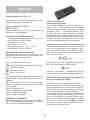
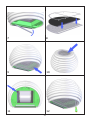
Prelevare dall’imballaggio la piastra a parete
e ssarla mediante i tasselli e le viti in dota-
zione (g.1).
Installare la parte in ceramica avendo mol-
ta cura nelle movimentazioni, come indicato
nelle gure 2 e 3.
AL ne di fare aderire, per quanto possibile,
la parte in ceramica alla parete, è possibile
agire sulle viti di regolazione indicate nelle
gure 4 e 5.
Attenzione: la parte in ceramica viene realiz-
zata in maniera artigianale quindi non è pos-
sibile ottenere delle forme regolari e omoge-
nee per tutte le superci.
Le viti vanno tirate in maniera manuale e
molto delicatamente altrimenti la ceramica
potrebbe rompersi.
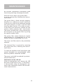
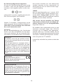
Inserire il fondo in acciaio, dalla parte inferio-
re della cappa (g. 6), quindi ssarlo median-
te le otto viti fornite in dotazione.
Installare la barra led nell’apposita sede (vedi
g.7), non prima di aver collegato il cavo di
alimentazione della barra led, mediante l’ap-
posito connettore bipolare.
Installare il ltro carbone direttamente sul l-
tro antigrasso in acciaio, mediante l’apposita
griglia di contenimento, come da gura 8.
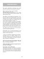
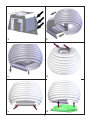
Installare il ltro antigrasso al prodotto
(g.9), collegare il cavo in acciaio con mo-
schettone al ltro, quindi avvicinare il ltro
antigrasso al prodotto ntanto non avvenga
l’aggancio magnetico.
Eettuare il collegamento del prodotto alla
rete elettrica.
Posizionare la griglia in acciaio nella parte
superiore del prodotto e ssarla mediante le
quattro viti fornite in dotazione. (g. 10).

8
FUNZIONAMENTO
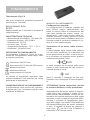
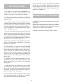
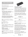
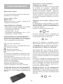
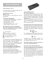
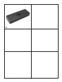
Telecomando (Fig. 13)
Alla prima accensione mantenere premuto il
tasto luce per 5 secondi.
RADIOCOMANDO SERIE
RC001
Radiocomando per il comando a distanza di
cappe aspiranti.
CARATTERISTIICHE TECNICHE
- Alimentazione pila alkalina: 12V mod.23A
- Frequenza di lavoro: 433,92 Mhz
- Combinazioni: 32.768
- Consumo max.: 25 mA
- Temperatura d’esercizio: -20 ÷ + 55 °C
- Dimensioni: 120x45x15mm.
DESCRIZIONE DI FUNZIONAMENTO
Il trasmettitore è dotato di 5 tasti per la ge-
stione del funzionamento della cappa, come
di seguito specicato:
: interruttore ON/OFF luce.
: interruttore ON (1° velocità) OFF motore.
: diminuire velocità.
: aumentare velocità.
: temporizzatore 10 minuti.
La velocità di aspirazione impostata viene
indicata mediante il led presente nel canale
perimetrale di aspirazione.
CONDIZIONE INIZIALE DI FUNZIONAMENTO
Il radiocomando viene fornito dal costrutto-
re pronto per l’uso, contenente già dei codici
predeniti di Fabbrica.
MODALITÀ DI FUNZIONAMENTO
Congurazione standard:
La congurazione di fabbrica prevede che
tutti i sistemi “ cappa - radiocomando “ ab-
biano lo stesso codice di trasmissione. Nel
caso siano installati due sistemi “ cappa - ra-
diocomando “ nello stesso locale o nelle im-
mediate vicinanze i sistemi avendo lo stesso
codice di trasmissione potrebbero essere in-
uenzati quindi è necessario cambiare il co-
dice di un solo radiocomando.
Generazione di un nuovo codice trasmis-
sione:
Il radiocomando viene fornito dalla fabbrica
con dei codici predeniti. Se si desidera una
nuova generazione di codici, occorre esegui-
re la procedura nel seguente modo: premere
contemporaneamente i tasti:
in modo continuo per 2 secondi, nello stesso
istante si avrà l’accensione dei Led, successi-
vamente premere i tasti:
(entro 5 secondi), 3 lampeggi dei Led indi-
cheranno che l’operazione è stata completa-
ta.
ATTENZIONE! Questa operazione cancella
in maniera denitiva i codici preesistenti.
Apprendimento del nuovo codice di trasmis-
sione: Dopo aver cambiato il codice di tra-
smissione nel radiocomando, occorre far ap-
prendere alla centrale elettronica della cappa
aspirante il nuovo codice nel seguente modo:
Premere il pulsante di spegnimento gene-
rale della cappa, ripristinare l’alimentazione
alla centrale elettronica, da questo momento
ci sono 15 secondi di tempo per premere il
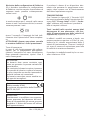
tasto Luce: per far sì che la centrale si
sincronizzi con il nuovo codice.

Il prodotto è dotato di un dispositivo elet-
tronico che permette lo spegnimento auto-
matico dopo quattro ore di funzionamento
dall’ultima operazione eseguita.
TEMPORIZZAZIONI
Con l’entrata in vigore dal 1° Gennaio 2015
dei nuovi regolamenti della Commissione Eu-
ropea EU65 “Energy label” e EU66 “ Ecode-
sign”, abbiamo reso conforme i prodotti in
base ai requisiti richiesti.
Tutti i modelli nelle versioni energy label
dispongono di una elettronica, con fun-
zioni di temporizzazione delle velocità di
aspirazione, superiore a 650m³/h.
In eetti i modelli con motore a bordo, con
portata massima superiore a 650m³/h, pre-
vedono la IVa velocità temporizzata dopo 6
minuti di funzionamento, Trascorsi i tempi di
cui sopra il motore di aspirazione passa alla
IIIa velocità in maniera automatica.
Il prodotto in modalità stand-by ha un con-
sumo inferiore a 0.5W.
9
Ripristino della congurazione di Fabbrica:
Se si desidera ripristinare la congurazione
di Fabbrica, occorre eseguire la procedura nel
seguente modo: premere contemporanea-
mente i tasti:
in modo continuo per 2 secondi, nello stesso
istante si avrà l’accensione dei Led, successi-
vamente premere i tasti:
(entro 5 secondi), 6 lampeggi dei Led indi-
cheranno che l’operazione è stata completa-
ta.
ATTENZIONE! Questa operazione cancella
in maniera denitiva i codici preesistenti.
Tasto d’emergenza:
In caso di non funzionamento del radioco-
mando, per lo spegnimento dell’apparec-
chiatura, intervenire sul tasto d’emergenza.
Dopo eventuali riparazioni, ripristi- nare il
tasto d’emergenza.
ATTENZIONE
La batteria deve essere sostituita ogni
anno per garantire la portata ottimale del
trasmettitore.
Per sostituire la batteria scarica rimuovere
il coperchio di plastica, togliere la batteria
in uso e inserirne una nuova rispettando la
polarità indicata nel contenitore.
La batteria usata deve essere smaltita ne-
gli appositi raccoglitori.
Il prodotto
Radiocomando RC001
è conforme alle speciche della Direttiva
R&TTE 99/5/EC.
AVVERTENZE
Cambiamenti o modiche non espressa-
mente approvate dal detentore del certi-
cato di compatibilità alle norme possono
invalidare il diritto dell’utente all’utilizzo
dell’apparecchiatura.
Rev. 0 26/08/14

Un’accurata manutenzione garantisce un
buon funzionamento ed un buon rendimento
nel tempo.
Una cura particolare va rivolta al ltro anti-
grasso, la rimozione del ltro avviene come
segue:
Il ltro antigrasso è ssato mediante magneti
pertanto, è suciente, inserire un utensile o
la punta di un coltello nell’apposita apertura
ovale e spingere verso l’alto per permettere
al ltro di uscire dalla sua sede. Vedi Fig. 12.
Per rimuovere completamente il ltro dalla
cappa occorre sganciare i due cavi di sicurez-
za, agendo sugli appositi moschettoni.
Il ltro carbone va rimosso, successivamente
alla rimozione del ltro antigrasso, agendo
sugli appositi agganci (g. 8).
La pulizia del ltro antigrasso può essere
eseguita a mano o in lavastoviglie.
La pulizia avviene in rapporto all’uso, almeno
una volta ogni due mesi.
Nel caso d’uso dell’apparecchio in versione
ltrante, è necessario sostituire il ltro car-
bone attivo periodicamente.
Il ltro carbone attivo si rimuove togliendo
prima il ltro antigrasso, seguendo le istru-
zioni sopra descritte.
Per la pulizia dell’apparecchio stesso viene
consigliato l’uso di acqua tiepida e detersivo
neutro, evitando l’uso di prodotti contenenti
abrasivi.
La sostituzione del cavo alimentazione deve
essere eseguita esclusivamente da personale
autorizzato.
Sostituzione della barra LED:
Utilizzando un utensile appropriato, rimuo-
vere la barra led dalla sua sede (vedi gura 7)
scollegarla elettronicamente mediante l’ap-
posito connettore quindi sostituirla con una
di pari caratteristiche.
10
MANUTENZIONE

INDICE
Warnings
Uses
Installation
Working
Maintenance
11
EN

12
WARNINGS
The appliance is not intended for use by young
children or inrm persons without supervi-
sion. Young children should be supervised to
ensure they do not play with the appliance.
* The minimum distance between the cooktop
surface and the lower part of the cooker hood
shall be 650 mm.
* The air sucked can’t be conveyed through
or into a duct used to let out fumes from ap-
pliances fed by energy other than electric po-
wer (eg. centralized heating, radiators, water-
heaters, etc.).
* When performing the electrical connections
on the appliance, please make sure that the
current-tap is provided with earth connection
and that voltage values correspond to those
indicated on the label placed inside the ap-
pliance itself.
Please disconnect the appliance from power
mains, before carrying out any cleaning or
maintenance operation.
If the appliance is not equipped with a nonse-
parable exible cable and plug, or with ano-
ther device ensuring omnipolar disconnection
from the mains, with an opening distance
between the contacts of at least 3 mm, then
such disconnecting devices must be provided
in the xed installation.
If the appliance is equipped with a power cord
and a plug, it shall be placed in such a way that
the plug can be reached easily.
* The use of materials which can burst into
ames (ambé) should be avoided in close
proximity of the appliance. When frying, ple-
ase pay particular attention to re risk due to
oil and grease. Being highly inammable, fried
oil is especially dangerous. Do not use unco-
vered electric grills.
In order to avoid possible re risk, all in-
structions for grease-lter cleaning and for
removing eventual grease deposits should be
strictly followed.
USES
The appliance can be arranged only for lte-
ring performances.
In its ltering version the air and fumes con-
veyed by the appliance are cleaned both by a
grease lter and by an ac tive coal lter, and
put again into circulation.
The charcoal lter is provided with appliance.

13
INSTALLATION
Before installing the appliance, make sure
that none of the parts is damaged in any way.
In case of damaged parts, contact your retai-
ler and do not proceed with installation.
The manufacturer declines any liability for
damages that may occur during the appliance
handling and installation operations.
Carefully read all of the instructions provided
in this manual, before installing the applian-
ce.
CAUTION: This appliance is made in ceramic
and therefore shall be handled very carefully
, and installed in a professional and proper
manner.
With the help of the drilling template provi-
ded with the appliance, drill the installation
holes in the wall, by using an 8mm diameter
twist drill.
Make sure to install the hood in such a way as
to have a minimum distance of 65 cm betwe-
en its bottom and the cook-top.
Take the wall plate from the packaging and
x it by using the dowels and screws supplied
(g.1).
Install and handle the ceramic component
very carefully, as shown in gures 2 and 3.
In order to have the ceramic component
‘adhering’ to the wall as much as possible,
we suggest you to act on the adjusting screws
shown gures 4 and 5, after installing it to
the wall.
Caution: the ceramic component is hand-
crafted , therefore it is not possible to obtain
regular and uniform shapes on all surfaces.
Screws shall be tightened manually and
lightly, in order to avoid the ceramic to
break up.
Fit the steel bottom component from the
hood lower side (g. 6), then x it by using
the eight screws supplied with the appliance.
Connect the led bar power cord by means of
the specic bipolar connector, and then t
the led bar in its specic seating (see g.7).
Fit the charcoal lter directly on the steel gre-
ase lter using the specic containment grid,
as shown in gure 8.
Fit the grease lter to the appliance (g. 9),
connect the steel wire with snap hook to the
lter , then move the grease lter close to the
appliance until it is magnetically coupled to
it.
Connect the appliance to the power supply.
Place the steel grid on top of the hood and x
it by using the four screws provided with the
appliance. (g. 10).

14
WORKING
Remote control (Fig.11)
channel radio control for cooker hood remo-
te.
At rst ignition, keep pressed the lighting
button for 5 seconds.
RC001
RADIO CONTROL
Radio control used for the remote operation
of ducted cooker hoods.
TECHNICAL DATA
- Alkaline battery powered: 12 V mod. 23 A
- Operating frequency: 433.92 Mhz
- Combinations: 32.768
- Max. consumption: 25 mA
- Operating temperature: -20 ÷ + 55 °C
- Dimensions: 120 x 45 x 15 mm.
OPERATING DESCRIPTION
The transmitter is equipped with 5 buttons
for cooker hood management, as specied
below:
: Light ON/OFF command.
: Motor ON (speed level 1) / OFF command.
: Reduce speed.
: Increase speed.
: 10-minute timer.
The set suction speed is indicated by the LED
in the suction perimeter channel.
To each color generated by the LED, it cor-
responds a specic speed, as shown below:
First speed WHITE
Second speed BLUE
Third speed DARK BLUE
Fourth speed RED
INITIAL OPERATING CONDITION
The manufacturer supplies the radio control
unit ready to be used with codes preset in the
Factory
OPERATION MODE
Standard conguration:
Standard conguration requires all “cooker
hoods – radio control - system” to be pro-
vided with the same transmission code. In
the event two cooker hoods – radio control
system are installed in the same room or ne-
arby, each system may aect the operation of
the another. Therefore, the code of one radio
control system must be changed.
Generatiing a new transmiissiion code:
The radio control system is provided with
preset codes. Should new codes be requi-
red, proceed as follows: Press simultaneously
buttons:
for two seconds. When Leds light on, press
buttons:
(within 5 seconds). Leds ashing 3 times in-
dicate
the procedure is completed.
WARNING! This operation deletes perma-
nently the preset codes.
Learniing the new transmiissiion code:
Once the transmission code is changed in the
radio control unit, the electronic central unit
of the cooker hood must be made to set the
new code in the fol- lowing way:
Press the main power-o button of the hood
and then restore power to the electronic con-
trol unit. Within the next 15 seconds, press
the Liight Button to synchronise the cen-
tral unit with the code.
Reset of the Factory coniguratiion:
To restore the Factory conguration, follow
the pro- cedure described below: press si-
multaneously buttons:
for 2 seconds. When Leds light on, press but-
tons:

TIMING
As a result of the new EU65 “Energy label”
and EU66 “Ecodesign” regulations issued by
the European Commission, which came into
force as from January 1st, 2015 , our pro-
ducts have been adapted to comply with the-
se new requirements.
All of the models complying with the ener-
gy label requirements, are equipped with
new electronics including a timer device
for suction speeds control, when the air ca-
pacity exceeds 650m³/h.
Internal motor models, with maximum air
capacity higher than 650m³/h, are equip-
ped with a timer device that automatically
switches the suction speed from 4th to 3rd
speed, after 6 minutes operation.
The energy consumption of the appliance in
stand – by mode is lower than 0.5W.
15
(within 5 seconds). Leds ashing 6 times in-
dicate the procedure is completed.
WARNING! This operation deletes perma-
nently the preset codes.
Emergency button:
In the event that the radio control does not
work, use the emergency button to switch
the appliance o. After any necessary repairs
have been performed, reset the emergency
button.
WARNIING
The battery should be replaced every year
to guarantee the optimal range of the
transmitter.
To replace the exhausted battery, take
the plastic lid o, remove the battery and
replace it with a new one, observing the
correct battery polarities.
Used batteries should be discarded in
special collection bins.
The below product:
RC001 Radiio Controll
complies with the specications set out in
the R&TTE Directive 99/5/EC.
WARNING
Any adjustments or modications which
have not been expressly approved by the
holder of the legal conformity certicate
may invalidate the user’s rights relating to
the operation of the device.
Rev. 0 26/08/14
The products are endowed with an electronic
device which allows the automatic switching
o after 4 hours working from the last ope-
ration.

An accurate maintenance guarantees good
functioning and long-lasting performance.
Particular care is due to the grease lter.
It can be removed by following the instruc-
tions below:
The grease lter is xed through magnets,
there fore it is sucient to insert a hand tool
or the tip of a knife in the dedicated opening
and push upwards in order to pull the lter
out of its place. See Fig. 12. In order to remo-
ve the lter from the hood, unhook the two
security cables opening their snap-hooks,
The active coal lter has to be removed after
the extrac tion of the grease lter by pusing
the specic handle (g.8).
The grease lter needs cleaning by regular
hand-washing or in dishwashers ev ery two
months at least or depending on its use.
The active coal lter needs to be periodically
replaced.
The charcoal lter is removed by removing
the grease lter rst, following the instruc-
tions above.
To clean the appliance itself tepid water and
neutral detergent are recommended, while
abrasive products should be avoided.
The power cord shall be replaced by authori-
zed personnel only.
Substitution of the LED bar:
Using an appropriate tool, remove the LED
bar from its seat (refer to Fig. 7), disconnect
it electronically using the appropriate con-
nector then substitute it with a LED bar with
same characteristics.
16
MAINTENANCE

INDICE
Instructions
Version de l’appareil
Installation
Fonctionnement
Entretien
17
FR

18
INSTRUCTIONS
* Les enfants, les personnes dépendantes ou
handicapée ne peuvent utiliser l’appareil que
si elles sont sous la surveillance d’adultes.
* La distance entre la surface de la table de
cuisson et la base de la hotte doit être d’au
moins 65 cm.
* L’air aspiré ne doit pas être canalisé dans un
conduit qui est utilisé pour évacuer les fumées
produites par des appareils alimentés par des
sources d’énergie autres que l’énergie électri-
que (installations de chauage central, radia-
teurs, chaue-eau, etc.).
* Lors du raccordement électrique assurezvous
que la prise de courant soit munie de mise à la
terre; vériez aussi que les valeurs de tension
correspondent à celles qui sont indiquées sur
la plaque des caractéristiques de l’appareil,
qui se trouve à l’intérieur de celui-ci.
*Avant de procéder à une opération d’entre-
tien ou de nettoyage quelconque, il faut dé-
brancher l’appareil.
Si votre appareil n’a pas pas de câble exible
qui ne peut pas être séparé, ni de prise ou bien
d’autre dispositif qui garantisse le débranche-
ment de tous les pôles du réseau, avec une
distance d’ouverture entre les contacts d’au
moins 3mm, ces dispositif de séparation du
réseau doivent alors être prévus dans l’instal-
lation xe.
Si l’appareil xé est pourvu du câble de l’ali-
mentation et une che, l’appareille doit être
placé de manière que la che soit facilement
accessible.
* Evitez d’utiliser des matériaux qui causent
des ambées à proximité de l’appareil. Dans
le cas de fritures, faites tout particulièrement
attention au danger d’incendie que représen-
tent les huiles et les corps gras.
A cause de son inammabilité l’huile usagée
est particulièrement dangereuse. N’utilisez
pas de grilles électriques découvertes.
VERSIONS DE L’APPAREIL
L’appareil fonctionne seulement en version
recyclage.
Dans la version recyclage l’air et les vapeurs
aspirés par l’appareil sont épurés par un ltre
à graisse et un ltre à charbon actif et puis
remis en circulation dans la pièce.
Le ltre à charbon est fourni avec la hotte.
Pour éviter des risques d’incendie possibles
suivez les instructions donnèes concernant
le nettoyage des ltres anti-graisses et sur
la façon d’enlever des dépots éventuels de
graisse sur l’appareil.

19
INSTALLATION
Avant de procéder a l’installation, vérier
que tous les composants soient en bon état;
dans le cas contraire, contacter le revendeur
et interrompre l’installation.
Le fabricant décline toute responsabilité pour
les dommages résultant d’une installation ou
manutention négligente ou incorrecte.
Veuillez lire attentivement toutes les instruc-
tions avant de procéder à l’installation.
ATTENTION: Ce produit est réalisé en céra-
mique et par conséquent nécessite d’une ma-
nipulation attentive et minutieuse, ainsi que
d’une installation professionnelle et soignée.
À l’aide du gabarit de perçage, fourni avec
l’appareil, eectuez les trous pour l’installa-
tion à la paroi en utilisant une mèche héli-
coïdale de 8mm.
Veillez à respecter la distance minimale de
65cm entre le dessous de la hotte et la table
de cuisson.
Sortez la plaque murale de l’emballage et
xez-la par les chevilles et les vis fournies
(Fig. 1).
Installez la pièce en céramique en faisant at-
tention aux manipulations, comme indiqué à
la gure 2 et 3.
Pour bien faire adhérer, autant que possible,
la pièce en céramique à la paroi, agissez sur
les vis de réglage, indiquées à la gure 4 et 5,
une fois nie l’installation à la paroi.
Attention: La pièce en céramique est fabri-
quée artisanalement, donc il n’est pas possi-
ble d’obtenir des formes régulières et homo-
gènes de toutes les surfaces.
Vissez les vis à la main et très délicate-
ment pour ne pas briser la céramique.
Insérez le fond en acier par le dessous de la
hotte (Fig. 6) et puis xez-le par les huit vis
fournies.
Montez la barre à Led dans son siège (Fig.
7), mais seulement après avoir branché le
cordon d’alimentation de la barre à Led à un
connecteur bipolaire.
Installez le ltre à charbon directement sur le
ltre à graisse en acier en utilisant la grille de
maintien appropriée (Fig. 8).
Installez le ltre à graisse (Fig. 9) et reliez le
câble en acier avec le mousqueton au ltre,
puis approchez le ltre à graisse à l’appareil
jusqu’il adhère solidement à l’aimant.
Branchez l’appareil au réseau électrique.
Placez la grille en acier sur le dessus du pro-
duit et xez la par les quatre vis fournies (Fig.
10).

20
FONCTIONNEMENT
Radiocommande (Fig. 11)
Au premier dèmarrage tenir le bouton lumiè-
re pressè pour 5 secondes.
RADIOCOMMANDE
SÉRIE BEFREE S6/S
Radiocommande pour le pilotage à distance
de hottes.
CARACTÉRIISTIIQUES TECHNIIQUES
- Alimentation par pile alcaline: 12V mod.23A
- Fréquence de travail: 433,92 Mhz
- Combinaisons: 32768
- Consommation maxi: 25 mA
- Température d’exercice: -20 ÷ + 55 °C
- Dimensions: 120x45x15 mm
DESCRIIPTIION DE FONCTIIONNEMENT
Le transmetteur est équipé de cinq touches
pour la gestion du fonctionnement de la hot-
te. Ces touches sont les suivantes:
: Interrupteur ON/OFF pour l’éclairage.
: Interrupteur ON (vitesse 1) /OFF pour le
moteur.
: réduire la vitesse.
: augmenter la vitesse.
: minuterie : 10 min.
La vitesse d’aspiration congurée est indi-
quée par le LED qui se trouve dans le canal
périmétral d’aspiration.
Pour chaque couleur générée par le LED il y
a une vitesse déterminée, comme indiqué ci-
dessous:
Première vitesse BLANC
Deuxième vitesse BLEU
Troisième vitesse BLEU FONCÉ
Quatrième vitesse ROUGE
CONDITION INITIALE DE FONCTIONNE-
MENT
La radiocommande est livrée par le fabricant
prête à l’emploi, elle contient déjà les codes
prédénis par l’usine.
MODE DE FONCTIIONNEMENT
Coniguratiion standard:
La conguration d’usine prévoit que tous les
systèmes “ hotte - radiocommande “ aient le
même code de transmission. Si deux systè-
mes “hotte – radiocom- mande” sont installés
dans la même pièce ou à proximité des systè-
mes ayant le même code de transmission, ils
pourraient être inuencés et il faudrait chan-
ger le code d’une seule radiocommande.
Generatiing a new transmiissiion code:
The radio control system is provided with
preset codes. Should new codes be requi-
red, proceed as follows: Press simultaneously
buttons:
for two seconds. When Leds light on, press
buttons:
(within 5 seconds). Leds ashing 3 times in-
dicate
the procedure is completed.
WARNING! This operation deletes perma-
nently the preset codes.
Learniing the new transmiissiion code:
Once the transmission code is changed in the
radio control unit, the electronic central unit
of the cooker hood must be made to set the
new code in the fol- lowing way:
Press the main power-o button of the hood
and then restore power to the electronic con-
trol unit. Within the next 15 seconds, press
the Liight Button to synchronise the cen-
tral unit with the code.
Reset of the Factory coniguratiion:
To restore the Factory conguration, follow
the pro- cedure described below: press si-
multaneously buttons:
La page est en cours de chargement...
La page est en cours de chargement...
La page est en cours de chargement...
La page est en cours de chargement...
La page est en cours de chargement...
La page est en cours de chargement...
La page est en cours de chargement...
La page est en cours de chargement...
La page est en cours de chargement...
La page est en cours de chargement...
La page est en cours de chargement...
La page est en cours de chargement...
La page est en cours de chargement...
La page est en cours de chargement...
La page est en cours de chargement...
La page est en cours de chargement...
La page est en cours de chargement...
La page est en cours de chargement...
La page est en cours de chargement...
La page est en cours de chargement...
La page est en cours de chargement...
La page est en cours de chargement...
La page est en cours de chargement...
La page est en cours de chargement...
-
 1
1
-
 2
2
-
 3
3
-
 4
4
-
 5
5
-
 6
6
-
 7
7
-
 8
8
-
 9
9
-
 10
10
-
 11
11
-
 12
12
-
 13
13
-
 14
14
-
 15
15
-
 16
16
-
 17
17
-
 18
18
-
 19
19
-
 20
20
-
 21
21
-
 22
22
-
 23
23
-
 24
24
-
 25
25
-
 26
26
-
 27
27
-
 28
28
-
 29
29
-
 30
30
-
 31
31
-
 32
32
-
 33
33
-
 34
34
-
 35
35
-
 36
36
-
 37
37
-
 38
38
-
 39
39
-
 40
40
-
 41
41
-
 42
42
-
 43
43
-
 44
44


