
OWNER’S MANUAL
Model number
700286
(Nylon brush)
700316
(Polypropylene brush)
Includes mounting instructions for:
Adaptor : # 700287
Adaptor : # 700288
Adaptor : # 700290-2
BERCO
Rotary Broom
for
LAWN, YARD, & GARDEN TRACTORS
BELT OR SHAFT DRIVE P.T.O.
103626 E-01
* ASSEMBLY * REPAIR PARTS
* OPERATION * MAINTENANCE
CAUTION:
READ & FOLLOW ALL SAFETY RULES & INSTRUCTIONS
BEFORE OPERATING YOUR EQUIPMENT

WARRANTY
LIMITED ONE YEAR ON BERCO TRACTOR ATTACHMENTS
For one year from date of purchase, Bercomac Limitée will repair or replace free of charge at Bercomac's option, any
parts which are defective as a result of defective materials or faulty workmanship.
COMMERCIAL OR RENTAL USE:
Warranty on Berco attachments used for commercial or rental purposes is limited to 90 days.
This warranty does NOT cover:
* Wear items, such as shear pins and belts.
* Repairs due to customer abuse or neglect.
* Pre-delivery set-up.
* In home service.
Warranty service is available by returning the "Berco" attachment to the authorized dealer.
BERCOMAC Limitée
92 Fortin N, Adstock, Québec, Canada, G0N 1S0

TABLE OF CONTENTS
INTRODUCTION ...................................................................................................................................................... 2
SAFETY PRECAUTIONS ....................................................................................................................................... 3
SAFETY DECALS .................................................................................................................................................... 5
ASSEMBLY
Step 1: Rotary Broom and Adaptor (700287) Preparation for Deluxe Subframe ................................. 6
Rotary Broom and Adaptor (700288) Preparation for Compact Subframe ............................. 7
Rotary Broom and Adaptor (700290-2) Preparation for P.T.O. Subframe .............................. 8
Step 2: Rotary Broom Installation ............................................................................................................ 10
Drive Mechanism Belt Installation on Deluxe Subframe ........................................................... 10
Drive Mechanism Belt Installation on Compact Subframe ....................................................... 10
Drive Mechanism Belt Installation on P.T.O. Subframe ............................................................ 10
Handle Installation ........................................................................................................................ 11
Verify Tire Pressure ...................................................................................................................... 11
OPERATION
Rotary Broom Angle Adjustment .............................................................................................................. 12
Pressure on the Brush Adjustment ........................................................................................................... 12
General Sweeping ..................................................................................................................................... 12
Snow Sweeping ......................................................................................................................................... 12
Lawn Dethatching and Leaf Raking .......................................................................................................... 12
MAINTENANCE & DISMOUNTING
Maintenance ............................................................................................................................................... 13
Brush Replacement ................................................................................................................................... 13
Dismounting ................................................................................................................................................ 13
End of Season Storage ............................................................................................................................. 13
TROUBLESHOOTING ............................................................................................................................................ 14
TORQUE SPECIFICATION TABLE ....................................................................................................................... 15
PARTS BREAKDOWN AND LISTS
Adaptor for Deluxe Subframe (700287) ................................................................................................... 16
Adaptor for Compact Subframe (700288) ................................................................................................ 18
Adaptor for P.T.O. Subframe (700290-2) ................................................................................................. 20
Rotary Broom ............................................................................................................................................. 22
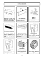
ATTACHMENTS ...................................................................................................................................................... 26
PAGE
1

INTRODUCTION
2
TO THE PURCHASER
This new attachment was carefully designed to give years of dependable service. This manual has been provided to
assist in the safe operation and servicing of your attachment.
NOTE: All photographs and illustrations in the manual may not necessarily depict the actual models or attachment, but
are intended for reference only and are based on the latest product information available at the time of publication.
Familiarize yourself fully with the safety recommendations and operating procedures before putting the machine to use.
Carefully read, understand and follow these recommendations and insist that they be followed by those who will use
this attachment.
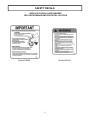
THIS SAFETY ALERT SYMBOL IDENTIFIES AN IMPORTANT SAFETY MESSAGE IN THIS MANUAL
THAT HELPS YOU AND OTHERS AVOID PERSONAL INJURY OR EVEN DEATH. DANGER,
WARNING, AND CAUTION ARE SIGNAL WORDS USED TO IDENTIFY THE LEVEL OF HAZARD.
HOWEVER, REGARDLESS OF THE HAZARD, BE EXTREMELY CAREFUL.
DANGER: Signals an extreme hazard that will cause serious injury or death if recommended precautions are
not followed.
WARNING: Signals a hazard that may cause serious injury or death if the recommended precautions are not
followed.
CAUTION: Signals a hazard that may cause minor or moderate injury if the recommended precautions are not
followed.
Record your attachment serial number and purchase date in the section reserved below (there is no serial number on
the subframe). Your dealer requires this information to give you prompt, efficient service when ordering replacement
parts . Use only genuine parts when replacements are required.
If warranty repairs are required please present this registration booklet and original sales invoice to your selling dealer
for warranty service.
This manual should be kept for future reference.
Please check if you have received all the parts for your kit with the list of the
bag and the list of the box.
7
SERIAL NUMBER : ____________________________
PURCHASE DATE : ____________________________
In this manual, right and left sides are determined by sitting on the tractor seat facing forward.
In this manual, "attachment" means accessories that you install on the tractor, such as, snowblower, rotary
broom, blade, rotary tiller, cab, subframe, etc...

SAFETY PRECAUTIONS
Careful operation is your best insurance against an accident. Read this section carefully before operating the tractor
and the rotary broom. All operators, no matter how experienced they may be, should read this and other manuals
related to the tractor and rotary broom before operating. It is the owner's legal obligation to instruct all operators in how
to safely operate the rotary broom.
TRAINING
This symbol, "Safety Alert Symbol", is used
throughout this manual and on the attachment’s
safety labels to warn of the possibility of serious
injury. Please take special care in reading and
understanding the safety precautions before
operating the tractor or the rotary broom.
1. Read this owner's manual carefully. Be thoroughly
familiar with the controls and proper use of the
rotary broom. Know how to stop the unit and
disengage the controls quickly.
2. Never allow children to operate the tractor nor the
rotary broom. Never allow adults to operate the
tractor nor the rotary broom without proper
instructions.
3. No one should operate the tractor nor the rotary
broom while intoxicated or while taking medication
that impairs the senses or reactions.
4. Keep the area of operation clear of all persons,
particularly small children and pets.
PREPARATION
1. Thoroughly inspect the area where the rotary broom
is to be used and remove door mats, all foreign
objects and the like.
2. Disengage all clutches and shift into neutral before
starting engine.
3. Do not operate the rotary broom without wearing
adequate outer garments. Avoid loose fitting
clothing that can get caught in moving parts. Wear
footwear that will improve footing on slippery
surfaces.
4. Handle fuel with care, it is highly flammable.
a) Use approved fuel container.
b) Never add fuel to a running engine or hot
engine.
c) Fill fuel tank outdoors with extreme care. Never
fill fuel tank indoors.
d) Never fill containers inside a vehicle, or on a
truck or a trailer bed with a plastic liner. Always
place containers on the ground, away from your
vehicle, before filling.
7
OPERATION
1. Do not put hands or feet near or under rotating
parts.
2. Exercise extreme caution when operating on or
crossing gravel drives, walks, or roads. Stay alert
for hidden hazards or traffic. Do not carry
passengers.
3. After striking a foreign object, stop the engine
(motor), disconnect the wire from the spark plug(s)
and keep wire away to prevent accidental starting.
Thoroughly inspect the rotary broom for any
damage and repair damage before using.
4. If the unit should start to vibrate abnormally, stop
the engine (motor) and check immediately for the
cause. Vibration is generally a warning of trouble.
e) When practical, remove gas-powered equipment
from the truck or trailer and refuel it on the
ground. If this is not possible, then refuel such
equipment on a trailer with a portable container,
rather than from a gasoline dispenser nozzle.
f) Keep the nozzle in contact with the rim of the
fuel tank or container opening at all times, until
refuelling is complete. Do not use a nozzle lock-
open device.
g) Replace fuel cap securely and wipe up spilled
fuel.
h) If fuel is spilled on clothing, change clothing
immediately.
4. Never attempt to make any adjustments while the
engine (motor) is running (except when specifically
recommended by manufacturer).
5. Always wear safety glasses or eye shields during
operation or while performing an adjustment or
repair to protect eyes from foreign objects that may
be thrown from the rotary broom.
6. Never modify the rotary broom or any part
without the written consent from the
manufacturer.
3

SAFETY PRECAUTIONS
WHENEVER YOU SEE THIS SYMBOL
7
IT MEANS:
WARNING!
BECOME ALERT !
YOUR SAFETY IS INVOLVED!
MAINTENANCE AND STORAGE
1. Check the mounting bolts at frequent intervals to
make sure that they are properly tightened
2. Never store the machine with fuel in the fuel tank
inside a building where ignition sources are present
such as hot water and space heaters, clothes
dryers, and the like. Allow the engine to cool before
storing in any enclosure.
3. Always refer to the owner’s manual when you store
the rotary broom.
4. Maintain or replace safety and instruction labels, as
necessary.
5. Inspect the tractor’s air filter every day. Clean it or
replace it. Change the oil more often when working
in dusty conditions. See the tractor owner’s manual.
5. Take all possible precautions when leaving the
machine unattended. Disengage the power take-
off, lower the attachment, set the parking brake,
stop the engine and remove the key.
6. When cleaning, repairing or inspecting the rotary
broom, make certain that all moving parts have
stopped. Disconnect wire from the spark plug(s)
and keep wire away to prevent accidental starting.
7. Do not run the engine indoors, except when
starting the engine and for transporting in or out of
the building. Do not operate or let motor run in a
storage area without ventilation because gas
contains carbon monoxide which is odorless,
colorless and can cause death.
8. Never sweep across the face of slopes. Exercise
extreme caution when changing direction on
slopes. Do not attempt to clear a steep slope.
9. Never operate the rotary broom without proper
guards, plates, or other safety protective devices in
place
10. Never tolerate bystanders in the working zone.
Never sweep in the direction of bystanders, the
brush might throw gravel or debris that can break
or damage property.
11. To sweep snow, use tire chains approved by the
manufacturer. You must use 100 lbs. of rear
counterweight for better traction and a greater
stability at all times when using a rotary broom that
is installed on the front of a tractor.
12. Never operate the rotary broom at high transport
speeds on slippery surfaces. Use care when
backing.
13. Do not carry passengers.
14. Disengage power to rotary broom when it is
transported or not in use
15. Never operate the rotary broom without good
visibility or light.
16. Keep the brush away from heat sources or flames.
17. Always wear a dust mask when working in a dusty
environment.
7
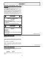
WARNING
7
TO PREVENT INJURIES AND FOR MORE
TRACTION WHEN USING AN ATTACHMENT:
-Rear counterweight of 100 lbs. minimum is
required to counterbalance the attachment’s
weight.
-Tractor manufacturer approved tire chains are
required.
-Do not operate on a slope greater than 10°.
-When dismounting an attachment remove rear
counterweights.
4

SAFETY DECALS
5
REPLACE IF DECALS ARE DAMAGED
SEE PARTS BREAKDOWN FOR DECAL LOCATION
Decal #102386 Decal #102384

ASSEMBLY
STEP 1
ROTARY BROOM & ADAPTOR (700287)
PREPARATION FOR DELUXE SUBFRAME
6
IMPORTANT: TORQUE ALL BOLTS ACCORDING
TO TORQUE SPECIFICATION TABLE (SEE TABLE
OF CONTENTS) WHEN STATED: TIGHTEN FIRMLY.
REFER TO PARTS BREAKDOWN SECTION FOR
PARTS IDENTIFICATION
Install the push frame (item 1) to the gear box frame
(item 2) by using two cone bearings (item 3), one on
top and the other underneath. Fill the space between
the bearings with grease.
Secure with a seal washer (item 4), the hollow portion
toward the top and a 3/4" nylon insert lock nut (item
5).
Tighten loosely enough to permit the push frame to
move freely.
Install the V-belt on the pulley (item 7).
Install the belt guard (item 8) on the push frame (item
1) and secure with two 1/4 x 3/4" bolts and nuts.
Install the joint block (item 9) on the latch rod and
secure with a retaining ring (item 10).
Install the control rod (item 11) in the joint block (item
9) and secure with a 2.5 mm hair pin (item 12).
Install the parking stands (item 1) in the stand holders
(item 4). Secure with a 5/32 x 1" cotter pin in the
upper hole (item 2) of each parking stand.
Set the parking stands in their most extended position
and secure in place with a 2.5 mm hair pin (item 3).
Go to Rotary Broom installation.
Prepare broom and adaptor
Install the parking stands

ASSEMBLY
Install the push frame (item 1) to the gear box frame
(item 2) by using two cone bearings (item 3), one on
top and the other underneath. Fill the space between
the bearings with grease.
Secure with a seal washer (item 4), the hollow portion
toward the top and a 3/4" nylon insert lock nut (item
5).
Tighten loosely enough to permit the push frame to
move freely.
Remove the belt guard (item 7).
Remove the 1/4" bolt (item 6) used as a belt guide.
Install the belt on the broom pulley (item 13) and on both
idlers as shown.
NOTE: If the drive mechanism kit includes a B-120 V-
belt (123" outside length) you must use a A-115 V-belt
#103181. OR
If the drive mechanism kit includes a B-112 V-belt (115"
outside length) you must use a A-107 V-belt #102884.
Re-install the 1/4" bolt (item 6) used as a belt guide.
Install the belt guard (item 7) on the push frame and
secure with two 1/4 x 3/4" bolts and nuts.
Install the joint block (item 9) on the latch rod and
secure with a retaining ring (item 10).
Install the control rod (item 11) in the joint block (item
9) and secure with a 2.5 mm hair pin (item 12).
Install the parking stands (item 1) in the stand holders
(item 4). Secure with a 5/32 x 1" cotter pin in the
upper hole (item 2) of each parking stand.
Set the parking stands in their most extended position
and secure in place with a 2.5 mm hair pin (item 3).
Go to Rotary Broom installation.
7
ROTARY BROOM & ADAPTOR (700288)
PREPARATION FOR COMPACT
SUBFRAME
IMPORTANT: TORQUE ALL BOLTS ACCORDING
TO TORQUE SPECIFICATION TABLE (SEE TABLE
OF CONTENTS) WHEN STATED: TIGHTEN FIRMLY.
REFER TO PARTS BREAKDOWN SECTION FOR
PARTS IDENTIFICATION
Prepare broom and adaptor
Install the parking stands

ASSEMBLY
Remove the three bolts (item 16) that hold the gear box
and guard (item 13).
Remove the gear box by sliding it towards the right.
Remove the pulley (item 7).
Install the new pulley (item 6) included with the adaptor
(the hub towards the top and the bottom even with the
gear box shaft).
Re-install the gear box and guard (item 13) in place and
make sure to re-install the rubber washers between the
gear box and frame wall.
Tighten the bolts firmly.
Install the push frame (item 1) to the gear box frame
(item 2) by completely loosening the nut used to
tighten the belt (item 14).
Install the belt on both pulleys at the same time as
you install the push frame.
Install a cone bearing (item 3) on the welded stud
(item 15). Fill the hub with grease and install the
second cone bearing (item 3) underneath. Secure
with a seal washer (item 4) the hollow portion towards
the top and a 3/4" nylon insert lock nut (item 5).
Tighten loosely enough to permit the push frame to
move freely.
Tighten the nut used to tighten the belt (item 14) to
compress the spring to 11/16" length (0.687" or 17 mm).
Install the belt guard (item 18) on the gear box guard
(item 13) with the two 1/4 x 1/2" hex bolts and flange
nuts. Tighten firmly.
Install the joint block (item 9) on the latch rod and
secure with a retaining ring (item 10).
Install the control rod (item 11) in the joint block (item
9) and secure with a 2.5 mm hair pin (item 12).
8
ROTARY BROOM & ADAPTOR (700290-2)
PREPARATION FOR P.T.O. SUBFRAME
IMPORTANT: TORQUE ALL BOLTS ACCORDING
TO TORQUE SPECIFICATION TABLE (SEE TABLE
OF CONTENTS) WHEN STATED: TIGHTEN FIRMLY.
REFER TO PARTS BREAKDOWN SECTION FOR
PARTS IDENTIFICATION
Prepare broom and adaptor

ASSEMBLY
Install the parking stands (item 1) in the stand holders
(item 4). Secure with a 5/32 x 1" cotter pin in the
upper hole (item 2) of each parking stand.
Set the parking stands in their most extended position
and secure in place with a 2.5 mm hair pin (item 3).
Install the tractor's section of the driveline into the
broom's driveline by aligning the stamped marks (item
2) (located between the splines at the end of the shaft)
with the large groove into the hollow tube (item 1) of the
broom section.
Only one position allows the shaft to be inserted.
Go to Rotary broom installation.
9
Install the parking stands
Install the driveline

ASSEMBLY
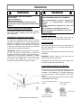
Attach the rotary broom to the subframe as shown.
Make sure the rotary broom is pushed in until locked
into place by the springs (item 1).
DRIVE MECHANISM BELT INSTALLATION ON
DELUXE SUBFRAME
Route the belt in the subframe, inside the left belt
guide, around the left pulley, (item 1), inside the right
belt guide, around the right pulley (item 2) and around
the tractor's drive pulley (item 3).
Go to handle installation.
DRIVE MECHANISM BELT INSTALLATION ON
COMPACT SUBFRAME
Install the belt on the drive mechanism pulley.
Make sure the belt is routed as shown.
Go to handle installation.
10
STEP 2
ROTARY BROOM INSTALLATION
7
WARNING
7
TO PREVENT INJURIES:
Stop the motor.
Apply parking brakes.
Remove the ignition key.
Disconnect the wire from the spark plug(s) and
keep away from spark plug(s) to prevent accidental
starting.
Install the rotary broom
Install the belt
Install the belt

HANDLE INSTALLATION
Install the 1/2 x 3" handgrip (item 2) on the handle
(item 1).
Insert the handle through the plastic grommet on the
handle support (item 3) and on the control rod (item
4).
Secure with a 2.5 mm hair pin.
NOTE: If the subframe includes a handle extension,
install it between the control rod (item 4) and the
handle (item 1).
VERIFY TIRE PRESSURE:
Attachments should raise 3" to 4" above the ground
(no more, no less) if not, check and adjust tractor tire
pressure as follows:
Front tires: 14-15 psi
Back tires: 7-8 psi
Tire pressure must be even on both sides of the
tractor.
ASSEMBLY
DRIVELINE INSTALLATION FOR P.T.O.
SUBFRAME
Connect the rotating driveline (item 5) to the tractor
P.T.O. spline shaft and be sure the driveline yoke is
securely attached to the tractor P.T.O.
After installing the rotary broom, make sure the
extension guard (item 4) is well installed and does not
touch the driveline at any time whatsoever. If the
extension guard needs to be raised, use a 1/4 x 1"
hex bolt (item 1) with a flange nut (item 2) on top and
one on the bottom. Adjust and tighten both nuts.
11
7
DANGER
7
ROTATING DRIVELINE
CONTACT CAN CAUSE DEATH.
KEEP AWAY
DO NOT OPERATE WITHOUT:
All driveline shields in place on tractor and
accessories.
Driveline securely attached at both ends.
7
DANGER
7
NEVER OPERATE THE ROTARY BROOM
WITHOUT:
Brush hood
Belt guard
Gear box guard
Extension guard and any other safety protection
devices in place.
Install the handle
Install the driveline

OPERATION
ROTARY BROOM ANGLE ADJUSTMENT
By turning the handle counter clockwise you unlock the
latch and by pulling or pushing, you set the angle 0° to
20° on each side.
12
7
WARNING
7
BEFORE MAKING ANY ADJUSTMENTS:
Stop the motor.
Apply parking brakes.
Remove the ignition key.
Disconnect the wire from the spark plug(s) and
keep away from spark plug(s) to prevent accidental
starting.
PRESSURE ON THE BRUSH ADJUSTMENT
By turning the adjustment screw (item 3) counter
clockwise, the gauge (item 2) moves higher and the
pressure of the brush on the ground increases. By
turning the adjusting screw clockwise, the gauge
moves lower on the gear box frame and the pressure
of the brush on the ground decreases.
IMPORTANT: Maintain the gauge (item 2) even with
the top of the gear box frame (item 1) or lower for
general hard surface sweeping. Adjust frequently to
compensate for brush wear. Remember to sweep
with the tips of the bristles like a broom and not with
the sides of the bristles like a mop. Too much
pressure can decrease the brush life up to 95%.
7
WARNING
7
TO PREVENT INJURIES AND FOR MORE
TRACTION WHEN USING AN ATTACHMENT:
-Rear counterweights of 100 lbs. minimum are
required to counter-balance attachment’s
weight.
-Tractor manufacturer approved tire chains are
required.
-Do not operate on slopes greater than 10°.
When dismounting an attachment remove rear
counterweights.
GENERAL SWEEPING
Minimize dust by reducing brush speed and by
sweeping after rain or on a day with high moisture.
SNOW SWEEPING
Adjust the gauge (item 3) to be even with the top of
gear box frame (item 2). The broom works well for
light snow removal.
Sweep with the wind blowing in the direction of broom
discharge.
WARNING: Foreign objects in the snow may be
thrown faster than the snow itself.
Frequently clean the snow and ice accumulation from
the top and bottom of the broom hood.
LAWN DETHATCHING AND LEAF RAKING:
Lower the broom on a hard surface and lift the brush
1" from the ground by turning the adjusting screw
clockwise. This adjustment is normally satisfactory
but you may raise or lower depending upon grass
height.
Low brush speed and ground speed is best for lawn
dethatching and leaf raking.
Adjust the pressure on the brush
Never sweep with the sides of
bristles! Sweep with the tips!
Do not mop!
Too much pressure=
Shortens brush life! Road surface
Flick action

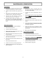
MAINTENANCE & DISMOUNTING
MAINTENANCE
1. Check oil level in gear box every fifty hours and fill
to plug level with SAE-90-EP oil when necessary.
2. Grease the wheel axles after every eight hours of
use.
3. Roller chain: do not lubricate when used in dusty
conditions. After use, wash clean and lubricate.
4. Adjust the roller chain frequently by moving the
chain idler sprocket to give 1/2" deflection.
5. Frequently clean the interior and exterior of hood.
Dirt, mud, ice, etc, accumulation adds weight on
the brush and could result in premature wear of
brush.
BRUSH REPLACEMENT:
See parts breakdown section for parts identification.
1. Remove the hood (item 57).
2. Loosen the chain idler sprocket (27).
3. Remove bolts from both flangettes (item 72) that
holds the brush hallow shaft.
4. Remove the brush hollow shaft (item 55) from the
broom frame (item
5. Loosen the set screw and remove the left bearing
(item 53) from the brush axle.
6. Remove the bolt (item 54) which retains the brush
tube to axle.
7. Remove the brush tube from axle.
8. Install the new brush by reversing the procedure.
9. Readjust the idler sprocket and chain tightener to
give 1/2" deflection.
13
DISMOUNTING
1. Select a level surface, set parking brake, stop
the engine, and remove the ignition key to
prevent accidental starting.
2. Straighten the broom perpendicular with the
tractor.
3. Set the parking stands in their most extended
position Make sure the brush bristles never
touch the ground.
4. Lower the broom to the ground.
5. Remove the hair pin from the handle and remove
handle.
6. Loosen and remove the belt from the tractor
drive pulley and idlers. Disconnect and remove
the driveline if applicable.
7. Detach the broom from the subframe by lifting
the spring locks and pulling back the broom one
side at a time.
8. Remove the rear counterweights.
END OF SEASON STORAGE
1. Clean the broom and inside of the hood.
2. Lubricate all grease fittings and all moving parts.
3. Store broom on parking stand. Make sure the
brush bristles never touch the ground.
4. If brush bristles are exposed to direct sunlight,
protect the bristles with a tarp.
5. Store the broom in a dry place.

TROUBLESHOOTING
14
PROBLEM POSSIBLE CAUSES CORRECTIVE ACTION
Brush wears out prematurely.
The brush turns jerkily.
The brush does not wear out
evenly.
The brush does not sweep well.
The pressure on the brush is not
well adjusted.
Reduce the pressure on the brush
when on the ground.
Maintain the gauge even with the
top of the gear box frame or lower
when sweeping hard surfaces.
Adjust frequently to compensate for
the wearing out of the brush.
Always sweep with the tips of the
bristles like a broom and not with
the sides of the bristles like a mop.
Too much pressure on the brush, it
will wear out up to 5 times faster.
Clean the inside and outside of the
hood frequently during operation.
Dirt, mud, ice, etc.. accumulation
adds weight on the brush and could
result in premature wear of the
brush.
The brush is too aggressive when
lawn dethatching or leaf raking.
The brush does not turn on the
grass.
Too much pressure on the brush. Lower the broom on a hard surface
and lift brush 1" from the ground by
turning the adjusting screw
clockwise.
Adjust from time to time if
necessary.
The chain wears out prematurely.
The sprocket wears out
prematurely.
Do not lubricate the chain during
operation. Wait until the job is
finished.
Wash the rotary broom and
lubricate the chain.
Let the broom turn a few moments
so the oil penetrates in the chain.
Check the chain adjustment
frequently (too tight, too loose).
The brush turns backwards. The belt is not installed in the right
way.
Remove the belt and reinstall as
explained in the instructions for belt
installation.
Loss of steering. Too much pressure on the brush. Reduce pressure on the brush. If
problem persists, contact your
dealer for more information.
The bristles take a bad form or
shape.
The broom was not stored on the
parking stands,
Wash the broom with warm water or
warm steam. Leave in raised
position and let it turn a few turns.
The brush should take its original
shape.

15
GENERAL TORQUE SPECIFICATION TABLE
USE THE FOLLOWING TORQUES WHEN SPECIAL TORQUES ARE NOT GIVEN
NOTE: These values apply to fasteners as received from supplier, dry or when lubricated with normal oil. They do not apply
if special graphited or moly disulphide greases or other extreme pressure lubricants are used. This applies to both UNF and
UNC threads.
TORQUE SPECIFICATION TABLE
SEE Grade No. 2 5 8 *
BOLT HEAD
IDENTIFICATION
MARKS AS PER GRADE
NOTE MANUFACTURING
MARKS WILL VARY
TORQUE TORQUE TORQUE
BOLT SIZE POUNDS FEET NEWTON-METERS POUNDS FEET NEWTON-METERS POUNDS FEET NEWTON-METERS
Inches Millimetre Min. Max. Min. Max. Min. Max. Min. Max. Min. Max. Min. Max. Max.
1/4" 6.35 5 6 6.8 8.13 911 12.2 14.9 12 15 16.3 30.3
5/16" 7.94 10 12 13.6 16.3 17 20.5 23.1 27.8 24 29 32.5 39.3
3/8" 9.53 20 23 27.1 31.2 35 42 47.5 57 45 54 61 73.2
7/16" 11.11 30 35 40.7 47.4 54 64 73.2 86.8 70 84 94.9 113.9
1/2" 12.7 45 52 61 70.5 80 96 108.5 130.2 110 132 149.2 179
9/16" 14.29 65 75 88.1 101.6 110 132 149.2 179 160 192 217 260.4
5/8" 15.88 95 105 128.7 142.3 150 180 203.4 244.1 220 264 298.3 358
3/4" 19.05 150 185 203.3 250.7 270 324 366.1 439.3 380 456 515.3 618.3
7/8" 22.23 160 200 216.8 271 400 480 542.4 650.9 600 720 813.6 976.3
1" 25.4 250 300 338.8 406.5 580 696 786.5 943.8 900 1080 1220.4 1464.5
*Thick nuts must be used with grade 8 bolts.
METRIC BOLT TORQUE SPECIFICATIONS
COARSE THREAD
Size Screw Grade No. Pitch (mm) Pounds Feet Newton-Meters Pitch (mm) Pounds Feet Newton-Meters
M6 4T 1.00 3.6 - 5.8 4.9 - 7.9 - - -
7T 5.8 - 9.4 7.9 - 12.7 - -
8T 7.2 - 10 9.8 - 13.6 - -
M8 4T 1.25 7.2 - 14 9.8 - 19 1.00 12 - 17 16.3 - 23
7T 17 - 22 23 - 29.8 19 - 27 25.7 - 36.6
8T 20 - 26 27.1 - 35.2 22 - 31 29.8 - 42
M10 4T 1.50 20 - 25 27.1 - 33.9 1.25 20 - 29 27.1 - 39.3
7T 34 - 40 46.1 - 54.2 35 - 47 47.4 - 63.7
8T 38 - 46 51.5 - 62.3 40 - 52 54.2 - 70.5
M12 4T 1.75 28 - 34 37.9 - 46.1 1.25 31 - 41 42 - 55.6
7T 51 - 59 69.1 - 79.9 56 - 68 75.9 - 92.1
8T 57 - 66 77.2 - 89.4 62 - 75 84 - 101.6
M14 4T 2.00 49 - 56 66.4 - 75.9 1.50 52 - 64 70.5 - 86.7
7T 81 - 93 109.8 - 126 90 - 106 122 - 143.6
8T 96 - 109 130.1 - 147.7 107 - 124 145 - 168
M16 4T 2.00 67 - 77 90.8 - 104.3 1.50 69 - 83 93.5 - 112.5
7T 116 - 130 157.2 - 176.2 120 - 138 162.6 - 187
8T 129 - 145 174.8 - 196.5 140 - 158 189.7 - 214.1
M18 4T 2.00 88 - 100 119.2 - 136 1.50 100 - 117 136 - 158.5
7T 150 - 168 203.3 - 227.6 177 - 199 239.8 - 269.6
8T 175 - 194 237.1 - 262.9 202 - 231 273.7 - 313
M20 4T 2.50 108 - 130 146.3 - 176.2 1.50 132 - 150 178.9 - 203.3
7T 186 - 205 252 - 277.8 206 - 242 279.1 - 327.9
8T 213 - 249 288.6 - 337.4 246 - 289 333.3 - 391.6
FINE THREAD

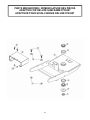
PARTS BREAKDOWN / NOMENCLATURE DES PIÈCES
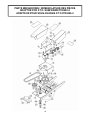
ADAPTOR FOR DELUXE SUBFRAME #700287
ADAPTEUR POUR SOUS-CHÂSSIS DELUXE #700287
16

Ref.
Réf. English description Description française Qty.
Qté.
Part #
Pièce #
1Nylon insert lock nut 3/4" n.c. (thin) Écrou à garniture de nylon 3/4" n.c. (mince) 1O/L
2Seal washer Rondelle d'étanchéité 1102289
3Cone bearing 0.75 Roulement conique 0.75 2102369
4Cup bearing Cuvette 2102370
5Push frame Châssis de poussée 1102204
6Belt guard Garde-courroie 1102284
7Flange nut 3/8" n.c. Écrou à bride 3/8" n.c. 2O/L
8Flat washer 7/16" hole Rondelle plate 7/16" trou 2O/L
9Hex. bolt 1/4" n.c. x 3/4" Boulon hex. 1/4" n.c. x 3/4" 2O/L
10 Flange nut 1/4" n.c. Écrou à bride 1/4" n.c. 2O/L
11 Hex. bolt 3/8" n.c. x 3/4" Boulon hex. 3/8" n.c. x 3/4" 2O/L
PARTS LIST / LISTE DES PIÈCES
O/L = Obtain locally/obtenir localement
17

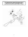
PARTS BREAKDOWN / NOMENCLATURE DES PIÈCES
ADAPTOR FOR COMPACT SUBFRAME #700288
ADAPTEUR POUR SOUS-CHÂSSIS COMPACT #700288
18
La page charge ...
La page charge ...
La page charge ...
La page charge ...
La page charge ...
La page charge ...
La page charge ...
La page charge ...
-
 1
1
-
 2
2
-
 3
3
-
 4
4
-
 5
5
-
 6
6
-
 7
7
-
 8
8
-
 9
9
-
 10
10
-
 11
11
-
 12
12
-
 13
13
-
 14
14
-
 15
15
-
 16
16
-
 17
17
-
 18
18
-
 19
19
-
 20
20
-
 21
21
-
 22
22
-
 23
23
-
 24
24
-
 25
25
-
 26
26
-
 27
27
-
 28
28


dans d''autres langues
- English: Bercomac 700286 User manual
Documents connexes
-
Bercomac BERCO 700286-1 Manuel utilisateur
-
-
-
-
-
-
-
-