NAPOLEON GPFL48MHP Le manuel du propriétaire
- Taper
- Le manuel du propriétaire

EN
FR
PG.25
www.napoleongrills.com
N415-0293 OCT 09.17
APPLY SERIAL NUMBER LABEL FROM CARTON
Serial No.
XXXXXX000000
MODEL NO.
DO NOT DISCARD
INSTALLER: LEAVE THIS MANUAL WITH THE APPLIANCE.
CONSUMER: RETAIN THIS MANUAL FOR FUTURE REFERENCE.
DANGER
IF YOU SMELL GAS:
• Shut o gas to the appliance.
• Exnguish any open ame.
• If odor connues, keep away from the
appliance and immediately call your gas
supplier or re department.
DANGER! CARBON MONOXIDE HAZARD
This appliance can produce carbon monoxide, which has no odor. Using it in an
enclosed space can kill you. Never use this appliance in an enclosed space such
as a camper, tent, car or home.
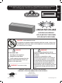
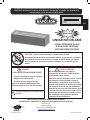
LINEAR PATIOFLAME
OUTDOOR GAS FIREPLACE
GPFL48 (WITHOUT ENCLOSURE)
GPFL48M (WITH ENCLOSURE)
0427GF002S
WARNING! For Outdoor Use Only.
WARNING
Do not try to light this appliance without
reading the “LIGHTING” instrucons secon of
this manual.
Do not store or use gasoline or other
ammable liquids or vapors in the vicinity of
this or any other appliance. An L.P. cylinder
not connected for use must not be stored in
the vicinity of this or any other appliance. If
the informaon in these instrucons is not
followed exactly, a re or explosion may result,
causing property damage, personal injury or
death.
This gas appliance must be used only outdoors in a well-venlated space and must not be used
inside a building, garage, screened-in porch, gazebo or any other enclosed area.
Wolf Steel Ltd.
214 Bayview Drive,
Barrie, Ontario, CANADA L4N 4Y8

2
EN
www.napoleongrills.com
N415-0293 OCT 09.17
Should deterioration of parts occur to the degree of non-performance (rusted
through or burnt through) within the duration of the warranted coverage, a
replacement part will be provided. The replacement component is the sole
responsibility of NAPOLEON defined by this Limited Warranty; in no event will
NAPOLEON be responsible for installation, labor or any other costs or expenses
related to the re-installation of a warranted part, for any incidental,
consequential, or indirect damages or for any transportation charges, labor costs
or export duties.
This Limited Warranty is provided in addition to any rights afforded to you by local
laws. Accordingly, this Limited Warranty imposes no obligation upon NAPOLEON
to keep parts in stock. Based on the availability of parts, NAPOLEON may at its
discretion discharge all obligations by providing a customer a prorated credit
towards a new product. After the first year, with respect to this Limited Warranty
NAPOLEON may, at its discretion, fully discharge all obligations with respect to
this warranty by refunding to the original warranted purchaser the wholesale price
of any warranted but defective part(s).
The bill of sale or copy will be required together with a serial number and a model
number when making any warranty claims from NAPOLEON.
NAPOLEON reserves the right to have its representative inspect any product or part
prior to honoring any warranty claim. You must contact NAPOLEON Customer Service
or an authorized NAPOLEON dealer to obtain the benefit of the warranty coverage.
napoleongrills.com
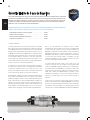
Napoleon President’s 3 Year Limited Warranty
NAPOLEON products are designed with superior components and materials, and are assembled by trained
craftsmen who take great pride in their work. The burner and valve assembly are leak tested and test-fired at a
quality test station. This grill has been thoroughly inspected by a qualified technician before packaging and shipping
to ensure that you, the customer, receive the quality product you expect from NAPOLEON.
NAPOLEON warrants that components in your new NAPOLEON product will be free from defects in material and
workmanship from the date of purchase, for the following period:
* Conditions and Limitations
This Limited Warranty creates a warranty period as specified in the
aforementioned table, for any product purchased through an authorized NAPOLEON
dealer, and entitles the original purchaser to the specified coverage in respect of
any component replaced within the warranty period, either by NAPOLEON or an
authorized NAPOLEON dealer, to replace a component of such product that has
failed in normal private use as a result of a manufacturing defect. The “50% off”
indicated in the table means the component is made available to the purchaser at
a 50% discount off the regular retail price of the component for the period
indicated. This Limited Warranty does not cover accessories or bonus items.
For greater certainty, “normal private use” of a product means that the product:
has been installed by a licensed, authorized service technician or contractor, in
accordance with the installation instructions included with the product and all
local and national building and fire codes; has been properly maintained; and has
not been used as a communal amenity or in a commercial application.
Similarly, “failure” does not include: over-firing, blow outs caused by
environmental conditions such as strong winds or inadequate ventilation,
scratches, dents, corrosion, deterioration of painted and plated finishes,
discoloration caused by heat, abrasive or chemical cleaners or UV exposure,
chipping of porcelain enameled parts, or damages caused by misuse, accident,
hail, grease fires, lack of maintenance, hostile environments such as salt or
chlorine, alterations, abuse, neglect or parts installed from other manufacturers.
Aluminum table top and pedestal ...................................................... 3 years
Stainless steel housing ......................................................................3 years
Stainless steel burner assembly ........................................................ 3 years
All other parts .................................................................................... 2 years

3
EN
www.napoleongrills.com
N415-0293 OCT 09.17
WARNING! For Outdoor Use Only.
WARNING! Improper installaon, adjustment, alteraon, service or maintenance can cause injury
or property damage. Read the installaon, operang and maintenance instrucons thoroughly before
installing or servicing this gas appliance.
Safe Operang Pracces
• THIS APPLIANCE IS HOT WHEN OPERATING AND CAN CAUSE SEVERE BURNS IF CONTACTED.
• Installaon and repair should be done by a qualied service person. The appliance should be
inspected before use and at least annually by a qualied service person. More frequent cleaning
may be required as necessary. It is imperave the control compartment, burners and circulang air
passageways of the appliance be kept clean.
• Do not operate appliance before reading and understanding operang instrucons. Failure to operate
appliance according to operang instrucons could cause re or injury.
• Risk of burns. The appliance should be turned o and cooled before servicing.
• Do not install damaged, incomplete or substute components.
• Young children should be carefully supervised when they are in the area of the appliance. Toddlers,
young children and others may be suscepble to accidental contact burns. A physical barrier is
recommended if there are at risk individuals in the vicinity. To restrict access to an appliance or
stove, install an adjustable safety gate to keep toddlers, young children and other at risk individuals
out of the vicinity and away from hot surfaces.
• Ensure you have incorporated adequate safety measures to protect infants/toddlers from touching
hot surfaces.
• Under no circumstances should this appliance be modied.
• Keep the packaging material out of reach of children and dispose of the material in a safe manner. As
with all plasc bags, these are not toys and should be kept away from children and infants.
• Do not leave appliance unaended when in use.
• For Outdoor use only.
• This appliance must not be used for cooking.
• This unit is not for use with solid fuel.
• Improper installaon, adjustment, alteraon, service, or maintenance can cause injury or property
damage. Read the installaon, operang and maintenance instrucons thoroughly before installing or
servicing this equipment.
• This appliance shall be used ONLY outdoors in a well-venlated space and shall NOT be used inside a
building, garage, or any other enclosed area.
• Cylinders must be stored outdoors in a well-venlated area out of reach of children. Disconnected
cylinders must have threaded valve plugs ghtly installed and must not be stored in a building, garage
or any other enclosed area.
• Storage of this appliance indoors is permissible only if it has been disconnected from its fuel supply
(natural gas line or LP gas cylinder).
• If it is evident there is excessive abrasion or wear, or the hose is cut, it must be replaced prior to the
appliance being put into operaon.
• Clothing or other ammable materials should not be hung from the appliance, or placed on or near
the appliance.
• Any guard or other protecve device removed for servicing the appliance must be replaced prior to
operang the appliance.
• Inspect the fuel supply connecon for signs of leakage (including the hose for LP models) before each
use of the appliance.
• The pressure regulator and hose assembly supplied with LP models must be used. Replacement
pressure regulators and hose assemblies must be those specied in this manual.
• The LP gas supply cylinder used with LP models must be constructed and marked in accordance with
the specicaons for LP-gas cylinders as required by the U.S. Department of Transportaon (DOT) or
the Canadian Transport Commission (CTC).
• The LP gas cylinder supply system must be arranged for vapour withdrawal.
• The LP-gas cylinder used must include a collar to protect the cylinder valve.
• When an LP model is not in use, the LP-gas must be turned o at the supply cylinder.
• To extend the life of your appliance, protect and cover it from the elements when not in use.
• This product must be installed by a licensed plumber or gas er when installed within the
commonwealth of Massachuses.

4
EN
www.napoleongrills.com
N415-0293 OCT 09.17
General Informaon
This gas appliance was tested and listed to Canadian and American Naonal Standards, ANSI Z21.97
(2014)/ CSA 2.41-2014 “Standard for Outdoor Decorave Gas Appliance” and CGA 2.17-M91 (R2014) “Gas-
Fired Appliance for use at High Altude” by OMNI-Test Laboratories. When an appliance is for connecon
to a xed piping system, the installaon must conform with local codes, or in the absence of local codes,
with the Naonal Fuel Gas Code, ANSI Z223.1/NFPA 54, Internaonal Fuel Gas Code, Natural Gas and
Propane Installaon Code, CSA B149.1, or Propane Storage and Handling Code, B149.2, as applicable.
This appliance should be installed and serviced by a qualied installer to conform with local codes.
Installaon pracces vary from region to region and it is important to know the specics that apply to your
area, for example: in Massachuses State:
• The appliance o valve must be a “T” handle gas cock.
• The exible connector must not be longer than 36 inches.
The appliance and its individual shut o valve must be disconnected from the gas supply piping system
during any pressure tesng of the system at test pressures in excess of 1/2 psig (3.5kPa).
This appliance must be isolated from the gas supply piping system by closing its individual manual shut o
valve during any pressure tesng of the gas supply piping system at test pressures equal to or less than 1/2 psig
(3.5kPa).
The following clearances to combusble materials must be maintained:
Sides (all around) - 24 inches (610mm)
Top - 72 inches (1830mm)
• Always keep the appliance area clear and free from combusble materials, gasoline, and other
ammable vapours and liquids.
• Do not locate appliance where it can get
excessively wet.
• Do not use this appliance if any part has been
under water. Immediately call a qualied
service technician to inspect the unit and to
replace any part of the control system and any
gas control, which has been underwater.
Geng Started
1. Remove all of the parts from the carton. Use the parts list to ensure all necessary parts are
included.
2. Do not destroy packaging unl the appliance has been installed and operates to your sasfacon.
3. Choose a locaon that meets the clearance to combusbles as outlined in this manual. Take into
consideraon the need for clear and easy access to the on/o valve AFTER the appliance is installed
and connected to the gas supply in order to safely turn o the burner.
4. Most stainless steel parts are supplied with a protecve plasc coang that must be removed prior
to using the appliance. The protecve coang has been removed from some of the parts during the
manufacturing process and may have le behind a residue that can be perceived as scratches or
blemishes. To remove the residue, vigorously wipe the stainless steel in the same direcon as the
grain.
5. Read and follow all instrucons in this manual before installing or servicing this gas appliance.
6. If you have any quesons about assembly or appliance operaon, or if there are damaged or missing
parts please call our Customer Soluons Department at 1-866-820-8686 between 9 AM and 5 PM
(Eastern Standard Time).
WARNING! This appliance is designed for non-combusble enclosures only, and must be installed
and serviced by a qualied installer to local codes.

5
EN
www.napoleongrills.com
N415-0293 OCT 09.17
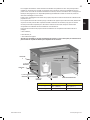
DIMENSIONS
INPUT
MODEL FUEL MAX. INPUT Btu/Hr
GPFL48N Natural Gas 60, 000
GPFL48P Propane Gas 60, 000
GAS INLET PRESSURES
NATURAL PROPANE
Inlet Pressure 7.0" w.c. 11.0" w.c.
MINIMUM CLEARANCE TO COMBUSTIBLES
INCHES MM
Side Walls 24 610
Top of unit to ceiling 72 1830
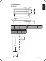
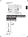
Specicaons
72”
(1829mm)
CENTRE OF PATIOFLAME
24”
(610mm)
24”
(610mm)
MAXIMUM
OVERHANG
13 1/2”
(343mm)
17 7/8”
(455mm)
47 1/2”
(1206mm)
51 7/8”
(1318mm)
11 7/8”
(302mm)
BURNER BASE ENCLOSURE
5 1/2”
(138mm)
BURNER BASE
ENCLOSURE

6
EN
www.napoleongrills.com
N415-0293 OCT 09.17
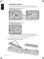
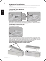
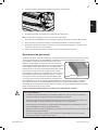
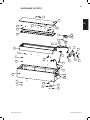
This unit is designed with some unique features that allow for maximum installaon exibility.
1. The gas supply to the enclosure can come either from underneath or through the side of the enclosure.
2. The burner unit can be used either with or without the enclosure. Simply li the unit out of the
enclosure to separate. A second person is required to guide out the gas hose /regulator when
removing the burner unit from the enclosure. The burner unit can be placed directly on combusble
surfaces, but the required clearances to the sides and top must sll be maintained.
Installaon Opons
Ensure
bushing
snaps into
side panel
as shown.
The gas supply is shown entering
the side of the enclosure.
The gas supply is shown entering
the boom of the enclosure.
Two people are required to li burner unit from enclosure
Li burner unit from enclsoure using handles
If the gas supply is to be routed through the side of the enclosure remove the (3) screws from the cover
plate so the hole is exposed. Snap the bushing into the side panel to secure the hose in place. Slide the
cover plate over, and reinstall.

7
EN
www.napoleongrills.com
N415-0293 OCT 09.17
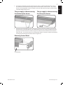
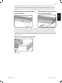
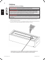
3. The supply can feed either into the side of the burner base, or is fed from below the base. The gas
line needs to be disconnected from the gas valve and reconnected in order to do this. This must be
done by a licensed gas er and the connecons need to be leak tested according to the leak tesng
instrucons before using the unit.
4. The burner unit can be built into a non-combusble enclosure. The control module can be removed
from the burner unit and located up to 12” away from the burner unit. A cap is provided to close the
opening in the side of the burner module. The gas line needs to be disconnected and reconnected in
order to do this. This must be done by a licensed gas er and the connecons need to be leak tested
according to the leak tesng instrucons before using the unit.
4 x N570-0013
The gas supply is shown entering
the boom of the burner.
The gas supply is shown entering
the side of the burner.
Removing Control Panel

8
EN
www.napoleongrills.com
N415-0293 OCT 09.17
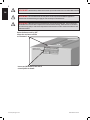
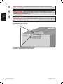
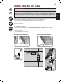
12.600” C-C Mounng Locaon
#8 Wood Screw
Recommended
Raise the burner unit by 3/4”
above the enclosure surface
as illustrated.
Insert cap (N510-0012) into end of
control panel as shown.
WARNING! Materials placed around the burner unit will get extremely hot. They must be non-
combusble and must be able to expand and contract without cracking. Raise the burner unit above
the enclosure by (3/4”) to reduce the temperature of the enclosure surface. Tiled cement board is the
preferred material.
WARNING! Cabinet frame, cabinet and counter top must be made from non-combusble material.
WARNING! You must have clear and easy access to the on/o valve AFTER the appliance is
installed and connected to the gas supply in order to safely turn o the burner.

9
EN
www.napoleongrills.com
N415-0293 OCT 09.17
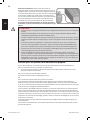
Gas Hook-Up Instrucons
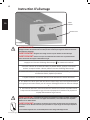
LP (Propane) Gas Cylinder Mounng
Aach cylinder retaining bracket to the base of the cylinder. Then secure to the surface to which it sits.
Cylinder should be on a level surface.
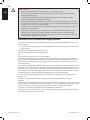
Cylinder Retaining Bracket
1. Fasten the bracket to the boom of the propane bole using
bolt and nut supplied.
2. Tighten the lag screw into the mounng surface
leaving approxi
mately 1/4” (6mm) of thread above the
surface.
3. Slide propane bole into posion so that the bracket slides
under the head of the lag screw.
4. Tighten the lag screw onto the bracket.
5. For fastening to a concrete surface a concrete anchor
will be required. (Not supplied)
Cylinder Connecon: Ensure the gas regulator hose
is kink free. Remove the cap or plug from the cylinder
fuel valve. Insert the black
QCC1 regulator nipple onto
the QCC1 fuel valve. Hand ghten clock
wise. Do not use
tools. Leak test all joints prior to using the appliance.
A leak test must be performed annually and each me
a cylinder is hooked up or if a part of the gas system is
replaced.
If this appliance is to be connected directly to a house
propane gas supply line, follow the instrucons for
the natural gas hook-up.
WARNING! If these instrucons are not followed exactly, a re causing death or serious injury may
occur.
Propane Cylinder Specicaons
A dented or rusty cylinder may be hazardous and should be checked by your propane supplier. Never use a
cylinder with a damaged valve. The LP-gas supply cylinder must be constructed and marked in accordance
with the U.S. D.O.T. Specicaons for LP-Gas Cylinders or the Standard for Cylinders, Spheres and Tubes for
Transportaon of Dangerous Good and Commission, CAN/CSA-B339, as applicable.
This appliance has been designed for use with a 20 lb. (9.1 kg) or 30 lb (13.6 kg) size propane cylinder only
(not supplied).
The LP-gas supply cylinder must be provided with a cylinder-connecon device compable with the
connecon for the appliance. The propane cylinder must be provided with a shut-o valve terminang in
a propane cylinder valve type QCC1, and a safety relief device having direct communicaon with the vapor
space of the cylinder. The cylinder supply system must be arranged for vapor withdrawal and the cylinder
shall include a collar to protect the cylinder valve. The LP-gas cylinder must be provided with a listed
overll protecon device (OPD). Do not store a spare LP-gas cylinder under or near this appliance. Never
ll the cylinder beyond 80 percent full.
Use only the pressure regulator and hose assembly provided with this appliance. Replacement pressure
regulators and hose assemblies must be specied by the manufacturer. The regulator supplies a pressure
of 11 inches. water column to the appliance and has a QCC1 type ng. Cylinders to be used with this
unit must be supplied with a QCC1 cylinder valve. A QCC1 cylinder has a posive seang connecon,
which will not allow gas ow unl a posive seal has been achieved. It is also equipped with an excess
ow device. In order to aain full ow to the appliance, the valve must be in the o posion when the
cylinder valve is turned on.
WARNING! A re will result if the gas supply hose makes contact with the underside of the
appliance.

10
EN
www.napoleongrills.com
N415-0293 OCT 09.17
CAUTION!
• Make sure cylinder valve is in its full o posion. (Turn clockwise to stop).
• Check cylinder valve features to ensure it has proper external mang threads. (Cylinder Valve
Marked: USE WITH TYPE 1)
• Inspect hose shipped with the unit for damage. Never aempt to use damaged or plugged
equipment. See your local LP Gas Dealer for repairs.
• When connecng regulator assembly to the cylinder valve, hand ghten black QCC1 nut clockwise
to a posive stop. DO NOT use a wrench to ghten. Use of a wrench may damage the quick closing
coupling nut and result in a hazardous condion.
• Locate the hose out of pathways where people may trip over it or in areas where the hose may be
subject to accidental damage.
• Open cylinder valve fully (counter-clockwise). Turn the on/o valve at the unit slowly to the on
posion and use a soapy water soluon to check all connecons for leaks as indicated in the
diagrams before aempng to light the appliance. If a leak is found, turn tank valve o and do not
use the appliance unl repairs can be made.
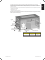
Enclosures For LP (Propane) Gas Supply Systems
If you build an enclosure for an LP gas cylinder, follow these recommended specicaons. You must also
follow local codes.
• An enclosure for an LP-gas cylinder shall be venlated by openings at both the upper and lower levels
of the enclosure.
This shall be accomplished by one of the following:
One side of the enclosure shall be completely open;
OR
For an enclosure having four sides, a top, and a boom:
a) At least two venlaon openings shall be provided in the sidewalls of the enclosure, located within 5 in
(127 mm) of the top of the enclosure, equally sized, spaced at a minimum of 90 degrees (1.57 rad), and
unobstructed. The opening(s) shall have a total free area of not less than 1 in
2
per lb (14.2 cm
2
/ kg) of
stored fuel capacity.
b) Venlaon opening(s) shall be provided at oor level of the enclosure and shall have a total free area of
not less than 1/2 in
2
per lb (7.1 cm
2
/ kg) of stored fuel capacity. If venlaon openings at oor level are in
a side wall, there shall be at least two openings. The boom of the openings shall be 1 in (25.4 mm) or less
from the oor level and the upper edge no more than 5 in (127 mm) above the oor level. The openings
shall be equally sized, spaced at a minimum of 90 degrees (1.57 rad), and unobstructed.
c) Every opening shall have minimum dimensions so as to permit the entrance of a 1/8 inch (3.2mm)
diameter rod.
Venlaon openings in sidewalls shall not communicate directly with other enclosures of the
appliance.
Cylinder valves shall be readily accessible for hand operaon. A door on the enclosure to gain access to the
cylinder valve is acceptable, provided it is non-locking and can be opened without the use of tools. Designs
using a cover to gain access to the cylinder and cylinder valve shall be provided with handles or
equivalent at a minimum of 180 degrees apart to facilitate liing of the cover.
There shall be a minimum clearance of 2 inches (50.8mm) between the lower surface of the oor of the LP
gas supply cylinder enclosure and the ground.

11
EN
www.napoleongrills.com
N415-0293 OCT 09.17
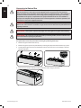
CYLINDER SIZE OPENING A AREA OPENING B AREA
20 lb (9.1 kg)
20 in
2
(130 cm
2
) 10 in
2
(65 cm
2
)
30 lb (13.6 kg)
30 in
2
(195 cm
2
) 15 in
2
(100 cm
2
)
The design of the enclosure shall be such that (1) the LP gas supply cylinder(s) can be connected,
disconnected and the connecons inspected and tested outside the cylinder enclosure; and (2) those
connecons which could be disturbed when installing the cylinder(s) in the enclosure can be leak tested
inside the enclosure.
The enclosure for the LP-gas cylinder shall isolate the cylinder from the burner compartment to provide:
a. Shielding from radiaon;
b. A ame barrier; and
c. Protecon from foreign material.
Be certain to mount or set the LP gas cylinder on a at surface and restrain it using a cylinder retaining
bracket to prevent it from pping.
OPENING
B
NON LOCKING DOOR
PARTITION TO ISOLATE CYLINDER
FROM PATIO FLAME
34” (864 mm)
RECOMMENDED
2” (51 mm)
MINIMUM
OPENING
A
5” (127 mm)
MAXIMUM
5” (127 mm)
MAXIMUM
1” (25.4 mm)
MAXIMUM

12
EN
www.napoleongrills.com
N415-0293 OCT 09.17
Conversion to Natural Gas
WARNING! This conversion kit shall be installed by a qualied service agency in accordance
with the manufacturer’s instrucons and all applicable codes and requirements of the Authority
Having Jurisdicon. If the informaon in these instrucons is not followed exactly, a re, explosion or
producon of carbon monoxide may result causing property damage, personal injury or loss of life.
The qualied service agency is responsible for the proper installaon of this kit. The installaon is
not proper and complete unl the operaon of the converted appliance is checked as specied in the
manufacturer’s instrucons supplied with the kit.
WARNING! To avoid the possibility of burns conversions should only be done when the pao
ame is cool. Ensure burner is turned o. Turn gas o at source and disconnect the pao ame before
beginning conversion.
WARNING! Glass embers may have sharp edges wear safety glasses and gloves when handling.
WARNING! This conversion must be performed by a licensed gas er, and all connecons must
be leak tested before operang the pao ame.
Your pao ame can be easily converted to natural gas by following these steps:
1. Remove the glass embers from the tray.
2. Remove the glass tray from the pao ame by removing the (18) screws that hold the tray in place.
3. Carefully li the glass tray from the pao ame and set aside. Take care not to damage or kink the
thermocouple wire.
4.
5. Disconnect the stainless steel ex connector from the orice using (2) wrenches.

13
EN
www.napoleongrills.com
N415-0293 OCT 09.17
6. Unscrew the propane orice from the inside of the burner as illustrated.
7. Replace the propane orice with the natural gas orice supplied.
Note: The air shuer has been factory set and does not need to be adjusted.
8. Reconnect the stainless steel ex connector to the orice and ghten using (2) wrenches.
9. Place the glass tray over the burner and fasten to the pao ame with the screws removed in step 2.
10. Fill out the conversion label included with your pao ame and apply it to the inside of the control
panel access door.
11. A leak test must be performed according to the leak tesng instrucons found in the manual.
Natural Gas Hook-Up
The gas appliance is designed to operate at an inlet pressure of 7 inches water column. The piping up to
the appliance is the responsibility of the installer. A exible metal connector is included to simplify the
installaon of the unit. Connect the exible connector to rigid
pipe, copper tube or an approved exible metal connector, which
complies with Z21.4/CSA 6.10. If using a gas hose (not supplied)
connect the ared end of the hose to the connector on the end
of the ex tube as illustrated. Tighten using two wrenches. (Do
not use thread sealer/pipe dope.) Leak test all joints prior to using
the appliance. Piping and valves upstream of the quick discon-
nect are not supplied. The gas supply pipe must be suciently
sized to supply the BTU/h specied on the rang plate, based on
the length of the piping run. The quick disconnect must not be
installed in an upward direcon and a readily accessible manual shut-o valve must be installed upstream
of, and as close to, the quick disconnect as is feasible.
Purge the gas supply line of any trapped air prior to the rst ring of the unit.
WARNING!
• The installaon must be performed by a licensed gas er, and all connecons must be leak tested
before operang the appliance.
• Ensure all hose connecons are ghtened using two wrenches. Do not use Teon tape or pipe dope
on any hose connecon.
• Ensure the hose does not contact any high temperature surfaces or it may melt and leak causing a
re.
• Locate the hose out of pathways where people may trip over it or in areas where the hose may be
subject to accidental damage.
• Leak test all the connecons using a soap and water soluon as per the leak tesng instrucons
found in the manual.

14
EN
www.napoleongrills.com
N415-0293 OCT 09.17
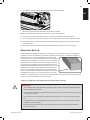
Glass Ember Installaon
WARNING! Do not use the pao ame without the glass embers in place.
WARNING! Glass embers may have sharp edges, wear safety glasses and gloves when handling.
Do
not change or substute the glass ember material provided with this appliance. If replacing, use
only replacement glass embers available from your local authorized dealer / distributor.
WARNING! Glass embers may have a ne oil residue that needs to be cleaned prior to
installaon. Clean the glass with mild dish soap, drain, rinse thoroughly and dry before installing.
1. Carefully pour the glass embers onto the appliance ember tray as shown.
2. Spread the glass embers over the tray and burner. The distribuon of clear glass over the burner will
inuence ame height.
3. The glass embers must cover the mesh area of the burner tray while ensuring no glass is placed on the
ignion poron of the burner as illustrated below.
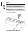
Finishing
ENSURE NO GLASS IS PLACED ON THE IGNITION PORTION OF THE BURNER,
DIFFICULTIES IN LIGHTING MAY RESULT.

15
EN
www.napoleongrills.com
N415-0293 OCT 09.17
Leak Tesng Instrucons
WARNING! A leak test must be performed annually, or if a part of the gas system is replaced.
WARNING! Never use an open ame to check for gas leaks. Be certain no sparks or open ames
are in the area while you check for leaks. Sparks or open ames will result in a re or explosion,
damage to property, serious bodily injury, or death.
Leak tesng: This must be done before inial use, annually, and whenever any gas components are
replaced or serviced. Do not smoke while performing this test, and remove all sources of ignion. See Leak
Tesng Diagram for areas to check. Turn all burner controls to the o posion. Turn gas supply valve on.
Brush a half-and-half soluon of liquid soap and water onto all joints and connecons of the regulator,
hose, manifolds and valves.
Bubbles will indicate a gas leak. Either ghten the loose joint or have the part replaced with one
recommended by the Napoleon Customer Soluons department and have the appliance inspected by a
cered gas installer.
If the leak cannot be stopped, immediately shut o the gas supply, disconnect it, and have the grill
inspected by a cered gas installer or dealer. Do not use the appliance unl the leak has been corrected.
DO NOT USE AN OPEN FLAME. DO NOT USE AN OPEN FLAME.
STOP
X

16
EN
www.napoleongrills.com
N415-0293 OCT 09.17
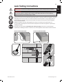
Lighng Instrucons
WARNING! Never use the appliance when it is raining. A cover has been provided to protect the
burner and glass embers when not in use. Remove the cover before starng the appliance.
WARNING! Keep face and body away from burner area when lighng.
WARNING! Ensure burner controls are in the o posion. Slowly turn on the gas supply valve.
1. Press and hold electronic igniter buon ( ).
2. Turn the burner control to the high posion, press and hold in. When the burner
lights, release the electronic igniter buon.
3. Connue to depress the burner control knob for 30 seconds and then release. If the
ame goes out, repeat the procedure.
4. Adjust the ame to the desired height with the burner control knob.
5. If the burner will not light with the electronic igniter, hold a lit long match or lit
long butane lighter to the ignion area of the burner and connue with step 2.
6. To shut down the burner turn the burner control knob clockwise to the o posion.
Then turn the gas o at the source (propane cylinder valve or natural gas supply
valve).
WARNING! The propane cylinder is equipped with an excess ow device. Unless burners are
turned o prior to turning the cylinder on, only small ames and low heat will be achievable.
WARNING! If the burner does not light within 10 seconds, turn the valve o and wait 5 minutes for
any gas to dissipate before repeang the procedure.
If lighng the unit with a match, clip the match into the supplied lighng rod.
Igniter
Open Cover

17
EN
www.napoleongrills.com
N415-0293 OCT 09.17
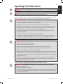
Operang The Pao Flame
Inial Lighng: When lit for the rst me, the appliance emits a slight odor. This is a normal temporary
condion caused by the “burn-in” of internal paints and lubricants used in the manufacturing process and
does not occur again. Simply run the main burner on high for approximately one-half hour.
WARNING! You must have clear and easy access to the on/o valve AFTER the appliance is
installed and connected to the gas supply in order to safely turn o the burner.
WARNING! Never use this appliance for other than the intended use. Do not use this appliance to
prepare food.
WARNING!
• Children and adults should be alerted to the hazards of high surface temperatures and should stay
away from the appliance to avoid burns or clothing ignion.
• Children should be carefully supervised when they are in the area of the appliance.
• Clothing or other ammable materials should not be hung from the appliance, or placed on or near
the appliance. The area above the enclosure may be extremely hot. Direct contact with these
surfaces should be avoided in order to prevent burns or clothing ignion.
• Any guard or protecve device removed for servicing the appliance must be replaced prior to
operang the appliance.
• Installaon and repair should be done by a qualied service person.
• The appliance should be inspected before each use and at least annually by a qualied service
person. More frequent cleaning may be required as necessary. It is imperave that the control
compartment, burners and circulang air passageways of the appliance be kept clean.
WARNING!
• Never use the appliance while it is raining.
• Always turn the appliance o when raining.
• Never splash any liquid on the glass / glass embers when the appliance is operang.
• The glass / glass embers will be extremely hot while operang, never try to touch them.
• Always ensure the appliance stands rmly on level ground.
• Never use the appliance if the burner is damaged. Inspect the burner before each use. Ensure that
no debris such as leaves; grass or other objects have entered or are on the appliance. If the burner
is damaged it must be replaced prior to using the appliance with a replacement burner specied by
your Napoleon dealer.
• Inspect the hose assembly before each use. If there is evidence of excessive abrasion or wear, or
if the hose is damaged it must be replaced prior to using the appliance with a replacement hose
assembly specied by your Napoleon dealer.
NOTE! The appliance has been designed with several safety features, which include a safety valve.
If the burner ame is exnguished the appliance will automacally shut down.
WARNING! Any modicaon to the appliance may compromise the safety of this appliance.
Special concern is as follows.
• Do not bypass thermocouple safety.
• Do not operate the appliance if any part has been under water. Immediately call a qualied service
technician to inspect the appliance and replace any part of the control system and any gas control,
which has been underwater.

18
EN
www.napoleongrills.com
N415-0293 OCT 09.17
WARNING! Glass embers may have sharp edges, wear safety glasses and gloves when handling.
Do not change or substute the glass ember material provided with this appliance. If replacing, use
only replacement glass embers available from your local authorized dealer / distributor.
WARNING! To avoid the possibility of burns, maintenance should be done only when the
appliance is cool. Avoid unprotected contact with hot surfaces. Ensure burner is turned o. Turn gas o
at source and disconnect the appliance before servicing. Clean the appliance in an area where cleaning
soluons will not harm decks, lawns, or paos. Do not use ammable, corrosive or abrasive cleaners.
Note: Stainless steel tends to oxidize or stain in the presence of chlorides and suldes, parcularly in
coastal areas and other harsh environments, such as the warm, highly humid atmosphere around pools
and hot tubs. These stains could be perceived as rust, but can be easily removed or prevented. To provide
stain prevenon and removal, wash all stainless steel and chrome surfaces every 3-4 weeks or as oen as
required with fresh water and/or stainless steel cleaner.
Control Panel: The control panel text is printed directly on the stainless steel and with proper
maintenance will remain dark and legible. To clean the panel, use only warm soapy water or stainless steel
cleaner available from your Napoleon dealer. Never apply abrasive cleaners on any stainless surfaces,
especially the printed poron of the control panel or the prinng will gradually rub o.
Maintenance / Cleaning Instrucons
WARNING! Hose: Check for abrasions, melng, cuts, and cracks in the hose. If any of these
condions exist, do not use the appliance. Have the part replaced by your Napoleon dealer or qualied
gas installer.
Cleaning Inside The Appliance: While washing your appliance, be sure to keep the area around the burner
and pilot assembly dry at all mes.
WARNING! If the gas control is exposed to water in any way, DO NOT try to use the appliance.
The gas control must be replaced.
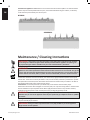
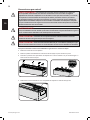
NORMAL
ABNORMAL
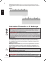
Each me the appliance is used: Perform a visual check of the burner ame paern. An abnormal ame
paern may be caused by blocked burner ports, inconsistent distribuon of glass embers, or refractory
rocks which are placed directly over burner ports.

19
EN
www.napoleongrills.com
N415-0293 OCT 09.17
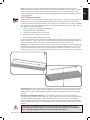
Burner: The burner is made from heavy wall 304 stainless steel, but extreme heat and a corrosive
environment can cause surface corrosion to occur. This can be removed with a brass wire brush. Inspect
the burner at least annually for cracks, insect nests, excessive corrosion or any other damage. If the
burner is damaged, it must be replaced with a burner specied by the manufacturer before the appliance
is put into operaon.
CAUTION! Beware of Spiders.
Spiders and insects are aracted to the smell of propane and natural gas. The burner is equipped with an
insect screen on the air shuer, which reduces the likelihood of insects building nests inside the burner
but does not enrely eliminate the problem. A nest or web can cause the burner to burn with a so yellow
or orange ame or cause a re (ashback) at the air shuer underneath the control panel. Other warning
signs that may indicate a problem are:
• Strong or unusual odor coming from the appliance.
• Connued diculty or delayed ignion.
• Flame appears either very short or very long.
• Flame only burns part way across the burner.
• Excessive soot building up on the glass embers.
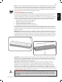
To clean the inside of the burner, it must be removed from the appliance: Remove the glass embers and
examine the burner. If dirty, clean with a wire brush. Remove the screws that aach the glass ember tray
and the nuts from the boom of the burner. Slide the burner back and up wards to remove.
Cleaning:
Use a exible venturi tube brush to clean the inside of the burner. Shake any loose debris from the
burner through the gas inlet. Check the burner ports and valve orices for blockages. Burner ports can close
over me due to debris and corrosion, use an opened paperclip or a drill bit to clean them. The ports are
easier to clean if the burner is removed from the appliance, but it can also be done with the burner installed.
Cleaning The Outer Appliance Surface: Do not use abrasive cleaners or steel wool on any painted, or
stainless steel parts of your Napoleon Appliance. Doing so will scratch the nish. Exterior surfaces should
be cleaned with warm soapy water. To clean stainless surfaces, use a stainless steel or a non-abrasive
cleaner. Always wipe in the direcon of the grain. Over me, stainless steel parts discolor when heated,
usually to a golden or brown hue. This discoloraon is normal and does not aect the performance of the
appliance
WARNING! The appliance area must be clear and free from combusble materials, gasoline
and other ammable vapors and liquids. Do not obstruct the ow of combuson and venlaon air.
Keep the venlaon opening of the cylinder enclosure free and clear of debris.
Reinstallaon: Reverse the procedure to reinstall the burner. Check that the valve enters the burner when
installing. Replace the glass embers. When the appliance is put back in service, check the burner ame
paern with the image in the Operang the Pao Flame secon to verify that the appliance is operang
correctly.

20
EN
www.napoleongrills.com
N415-0293 OCT 09.17
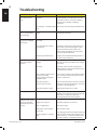
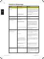
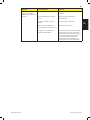
Troubleshoong
Problem Possible Causes Soluon
Low heat / Low ame
when valve turned to
high.
For propane - improper lighng
procedure.
For natural gas - undersized supply
line.
Ensure lighng procedure is followed carefully.
The valve must be in the o posion when the
tank valve is turned on. Turn tank on slowly to
allow pressure to equalize. See lighng
instrucons.
Pipe must be sized according to installaon code.
Burners burn with yellow
ame, accompanied by
the smell of gas.
Possible spider web or other
debris.
Thoroughly clean burner venturi. See general
maintenance instrucons.
Burner will not light with
the igniter, but will light
with a match.
Dead baery / or installed
incorrectly.
Loose electrode wire or switch
terminal wires.
Improper gap at electrode p.
Replace with heavy duty baery.
Check that electrode wire is rmly pushed onto
the terminal on the back of the igniter. Check
that the lead wires from the module to the
ignion switch (if equipped) are rmly pushed
onto their respecve terminals.
The gap can be adjusted by bending the p in or
out. Unl a spark is achieved.
Burner will not stay lit
when control knob is
released.
Knob not being held in long
enough.
Too windy.
Glass or debris in ignion area of
the burner prevenng
thermocouple from being fully
engulfed in ame.
Dirty thermocouple or
thermocouple connecon.
Faulty thermocouple or valve.
Thermocouple must have me to heat up – hold
the knob in for 30 seconds aer the burner lights,
then release
Unit will shut down if winds are greater than
10mph (16km/h). Either locate to dierent area
or use when it is less windy.
Ensure there is no glass or other debris in ignion
area, and that the small hole below the thermo-
couple is unobstructed.
Clean the thermocouple and clean the connecon
between the valve and thermocouple. Ensure the
connecon is properly ghtened.
Replace thermocouple and / or valve.
Humming regulator. Normal occurrence on hot days. This is not a defect. It is caused by internal
vibraons in the regulator and does not aect the
performance or safety of the gas heater.
Humming regulators will not be replaced.
Burner output on “high”
seng is too low. (Rum-
bling noise and uer-
ing blue ame at burner
surface.)
Lack of gas.
Supply hose is pinched.
Dirty or clogged orice.
Spider webs or other maer in
venturi tube.
Propane regulator in “low ow”
state.
Check gas level in propane cylinder.
Reposion supply hose as necessary.
Clean burner orice.
Clean out venturi tube.
Ensure lighng procedure is followed carefully. All
valves must be in the o posion when the tank
valve is turned on. Turn tank on slowly to allow
pressure to equalize. See lighng instrucons.
La page est en cours de chargement...
La page est en cours de chargement...
La page est en cours de chargement...
La page est en cours de chargement...
La page est en cours de chargement...
La page est en cours de chargement...
La page est en cours de chargement...
La page est en cours de chargement...
La page est en cours de chargement...
La page est en cours de chargement...
La page est en cours de chargement...
La page est en cours de chargement...
La page est en cours de chargement...
La page est en cours de chargement...
La page est en cours de chargement...
La page est en cours de chargement...
La page est en cours de chargement...
La page est en cours de chargement...
La page est en cours de chargement...
La page est en cours de chargement...
La page est en cours de chargement...
La page est en cours de chargement...
La page est en cours de chargement...
La page est en cours de chargement...
La page est en cours de chargement...
La page est en cours de chargement...
La page est en cours de chargement...
La page est en cours de chargement...
La page est en cours de chargement...
La page est en cours de chargement...
La page est en cours de chargement...
La page est en cours de chargement...
-
 1
1
-
 2
2
-
 3
3
-
 4
4
-
 5
5
-
 6
6
-
 7
7
-
 8
8
-
 9
9
-
 10
10
-
 11
11
-
 12
12
-
 13
13
-
 14
14
-
 15
15
-
 16
16
-
 17
17
-
 18
18
-
 19
19
-
 20
20
-
 21
21
-
 22
22
-
 23
23
-
 24
24
-
 25
25
-
 26
26
-
 27
27
-
 28
28
-
 29
29
-
 30
30
-
 31
31
-
 32
32
-
 33
33
-
 34
34
-
 35
35
-
 36
36
-
 37
37
-
 38
38
-
 39
39
-
 40
40
-
 41
41
-
 42
42
-
 43
43
-
 44
44
-
 45
45
-
 46
46
-
 47
47
-
 48
48
-
 49
49
-
 50
50
-
 51
51
-
 52
52


NAPOLEON GPFL48MHP Le manuel du propriétaire
- Taper
- Le manuel du propriétaire
dans d''autres langues
- English: NAPOLEON GPFL48MHP Owner's manual
Documents connexes
-
NAPOLEON GPFL48 Le manuel du propriétaire
-
-
-
-
-
-
-
-
-