
16 : 9 LCD KIT
BKNW-26
INSTALLATION MANUAL
1st Edition
! WARNING
This manual is intended for qualified service personnel only.
To reduce the risk of electric shock, fire or injury, do not perform any servicing other than that
contained in the operating instructions unless you are qualified to do so. Refer all servicing to
qualified service personnel.
! WARNUNG
Die Anleitung ist nur für qualifiziertes Fachpersonal bestimmt.
Alle Wartungsarbeiten dürfen nur von qualifiziertem Fachpersonal ausgeführt werden. Um die
Gefahr eines elektrischen Schlages, Feuergefahr und Verletzungen zu vermeiden, sind bei
Wartungsarbeiten strikt die Angaben in der Anleitung zu befolgen. Andere als die angegeben
Wartungsarbeiten dürfen nur von Personen ausgeführt werden, die eine spezielle Befähigung
dazu besitzen.
! AVERTISSEMENT
Ce manual est destiné uniquement aux personnes compétentes en charge de l’entretien. Afin
de réduire les risques de décharge électrique, d’incendie ou de blessure n’effectuer que les
réparations indiquées dans le mode d’emploi à moins d’être qualifié pour en effectuer d’autres.
Pour toute réparation faire appel à une personne compétente uniquement.


1-1 (E)
BKNW-26
Section 1
Installation
Purpose of this manual
This manual is an installation manual of 16 : 9 LCD kit
BKNW-26.
This manual is intended for system and service engineers,
so describes information regarding installation.
Related manual
Besides this installation manual, the following manual is
available for BKNW-26.
. Maintenance Manual (available on request)
This manual describes the information for the mainte-
nance of this unit and the information that premises the
parts level service.
If this information is required, please contact your local
Sony Sales Office/Service Center.
1-1. Specifications of DP-265B Board
General
Dimensions (w/h) 163 x 145 mm
Mass approx. 78 g
Power requirements +5 V dc: 110 mA
+12 V dc: 125 mA
Power consumption approx. 2.2 W
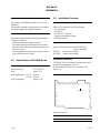
1-2. Installation Overview
Components
BKNW-26 is composed of the following items:
. DP-265B board
. WIDE label
. Screw P2.6 x 5 (4 pieces)
. Operation and installation guide
. Installation manual
Applicable models
Digital videocassette recorder DNW-A25/A25P or
DNW-A220/A220P
DP ROM: Version 2.00 and higher
KY ROM: Version 2.00 and higher
Installation of BKNW-26
The BKNW-26 (DP-265B board) is replaced with the DP-
265/265A board installed in the VTR.
Be sure to attach the BKNW-26 in accordance with
Section 1-3.
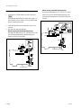
LED on the DP-265B board
Function of the LED
Ref No. Description
D401 Blinks when the MPU on the DP-265B board operates.
D401
A
2
1
3
4
5
6
7
BCDEFG JK

1-2 (E)
BKNW-26
B2 x 4
PS3 x 10
B2 x 4
Shield plate (A)
*
Bonding wire
*
* : The parts marked by an asterisk are not used in the
units of 910 lot or later.
Shielding plate (A)
assembly
*
(Unnecessary part)
Shield wire
*
(Unnecessary part)
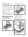
1-3. Installation Procedures
Checking the DP and KY ROM version
1. Turn on the power of the VTR while pressing the
PAGE button and the F2 button, then release the
buttons after switching the display of “INITIALIZ-
ING”.
2. Press the F2 button once, then press the PAGE button
three or four times. And then check the each version of
the DP and KY ROMs displayed on the sub LCD
screen.
DP ROM: Version 2.00 and higher
KY ROM: Version 2.00 and higher
n
When each ROM version is lower than 2.00, the
picture is not displayed properly even if the BKNW-26
is correctly installed. When updating the software is
required, contact your local Sony Sales Office/Service
Center.
Removing the DP-265/265A board
1. Turn off the power of the VTR.
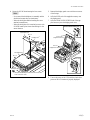
2. Open the display panel, and remove the four screws
fixing the display panel.
1-3. Installation Procedures
3. Close the display panel once, then remove the display
panel cover in the upper direction.
4. Remove the four screws (B2 x 4).
If the following parts are attached, remove them:
1) bonding wire, 2) shield plate (A),
3) shield plate (A) assembly, 4) shield wire.
n
After removing the shield wire, mount only the screw
(PS3 x 10) to its original position.
P2.6 x 5
Display panel
P2.6 x 5
Display panel cover

1-3 (E)
BKNW-26
5. Remove the adhesive tape from the DP-265/265A
board.
6. Disconnect the harnesses from the DP-265/265A
board, and then unfasten them from the lead pin.
For the DP-265 board
Disconnect the harnesses from CN5, CN6 and CN1.
For the DP-265A board
Disconnect the harnesses from CN5, CN6, CN10,
CN11 and CN12.
7. Disconnect the DP-265/265A board by lifting it from
the CN-1541 board.
m
. When the shield plate (B) is attached, slide it in the
arrow direction.
. When the DP shield case is attached, remove it also.
n
Improvement have eliminated reattaching some parts.
**
**
* in illustrations (up to 910 lot) Re-attachment
Shielding plate (A) assembly Not required
Shield wire Not required
Screw (PS3 x 10) Required
Shield plate Required
Bonding wire Required
DP shield case Required
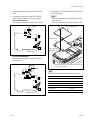
1-3. Installation Procedures
CN1
CN6
CN5
Lead pin
DP-265 board
Tape
CN10
CN11
CN12
CN6
CN5
Lead pin
DP-265A board
Tape
DP-265/265A board
CN-1541 board
DP shield case
*
Shield plate (B)
*
CN7
* : The parts marked by an asterisk are not used in the
units of 910 lot or later.

1-4 (E)
BKNW-26
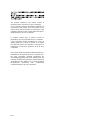
Attaching the BKNW-26 (DP-265B board)
1. Connect the DP-265B board to the CN-1541 board.
n
When having removed the DP shield case in step 7 of
the removal, be sure to attach it to the DP-265B board
before connecting the board.
2. Affix the tape that has been removed in step 6 of the
removal.
3. Reconnect the removed harnesses.
When having removed three harnesses
Reconnect the harnesses to CN1, CN5 and CN6 on the
DP-265B board respectively, and then clamp the
harness for CN1 by the lead pin.
When having removed five harnesses
Reconnect the harnesses to CN5, CN6, CN10, CN11
and CN12 on the DP-265B board respectively, and
then clamp the harnesses for CN10 and CN12 by the
lead pin.
1-3. Installation Procedures
CN1
Lead pin
DP-265B board
Tape
CN6
CN5
CN10
CN11
CN12
Lead pin
DP-265B board
Tape
CN6
CN5

1-5 (E)
BKNW-26
4. Secure the DP-265 board reusing the four screws.
m
. Do not attach the shield plate (A) assembly and the
shield wire because they are unnecessary.
. When the shield plate and the bonding wire were
attached, reattach them.
. When the shield plate (B) is attached, secure it with
DP-265B board by the screws after sliding it in the
arrow direction.
5. Reattach the display panel cover with the new screws
of the fittings.
6. Affix the WIDE seal of the supplied accessory onto
the display panel.
7. Affix the 16:9/4:3 WIDE SCREEN seal of the sup-
plied accessory onto the display panel cover.
8. Turn on the power of the VTR, and then check that a
picture of the LCD monitor is properly displayed.
1-3. Installation Procedures
B2 x 4
B2 x 4
Shield plate (A)
*
DP-265B board
Bonding wire
*
Shield plate (B)
*
* : The parts marked by an asterisk are not used in the
units of 910 lot or later.
P2.6 x 5
(Supplied accessory)
P2.6 x 5
(Supplied accessory)
16:9/4:3 WIDESCREEN seal
WIDE seal


BKNW-26
The material contained in this manual consists of
information that is the property of Sony Corporation.
Sony Corporation expressly prohibits the duplication of
any portion of this manual or the use thereof for any
purpose other than the operation or maintenance of the
equipment described in this manual without the express
written permission of Sony Corporation.
Le matériel contenu dans ce manuel consiste en
informations qui sont la propriété de Sony Corporation.
Sony Corporation interdit formellement la copie de
quelque partie que ce soit de ce manuel ou son emploi
pour tout autre but que des opérations ou entretiens de
l’équipement à moins d’une permission écrite de Sony
Corporation.
Das in dieser Anleitung enthaltene Material besteht aus
Informationen, die Eigentum der Sony Corporation sind.
Die Sony Corporation untersagt ausdrücklich die
Vervielfältigung jeglicher Teile dieser Anleitung oder den
Gebrauch derselben für irgendeinen anderen Zweck als
die Bedienung oder Wartung der in dieser Anleitung
beschriebenen Ausrüstung ohne ausdrückliche
schriftliche Erlaubnis der Sony Corporation.

Printed in Japan
Sony Corporation 2001. 12 08
B&P Company ©2001
BKNW-26 (SY) J, E
3-206-722-01
-
 1
1
-
 2
2
-
 3
3
-
 4
4
-
 5
5
-
 6
6
-
 7
7
-
 8
8
-
 9
9
-
 10
10


dans d''autres langues
- English: Sony BKNW-26 Installation guide
Documents connexes
Autres documents
-
ESAB 300 MST ARCMASTER® Inverter Arc Welder Manuel utilisateur
-
 Thermal Arc Inverter Arc Welder Model LM300 CC/CV Manuel utilisateur
-
 Thermal Arc Inverter Arc Welder Model 400GMS CC/CV Manuel utilisateur
-
-
-
Haier 1U24AP2VHA Manuel utilisateur
-
Hitachi RAC-D18EX3 Manuel utilisateur
-
Samsung WF17T6300GW Guide de démarrage rapide
-
Thermal Dynamics Plasma Cutting System Model Drag-Gun Plus Manuel utilisateur
-

