STIHL MS 461 R Manuel utilisateur
- Catégorie
- Jouets
- Taper
- Manuel utilisateur

STIHL MS 461 R
Instruction Manual
Notice d’emploi


Original Instruction ManualPrinted on chlorine-free paper
Printing inks contain vegetable oils, paper can be recycled.
© ANDREAS STIHL AG & Co. KG, 2019
0458-180-8221-A. VA2.A19.
0000006424_004_GB
MS 461 R
English
1
This instruction manual is protected by copyright. All rights reserved, especially the rights to reproduce, translate and process
with electronic systems.
Contents
Dear Customer,
Thank you for choosing a quality
engineered STIHL product.
It has been built using modern
production techniques and
comprehensive quality assurance.
Every effort has been made to ensure
your satisfaction and trouble-free use of
the product.
Please contact your dealer or our sales
company if you have any queries
concerning this product.
Your
Dr. Nikolas Stihl
Guide to Using this Manual 2
Safety Precautions 2
Mounting the depth limiter 3
Adjusting Cutting Depth 3
Chain lubrication 4
Converting a chain saw 4
Tensioning the saw chain (depth
limiter installed) 7
Checking the chain tension (depth
limiter installed) 7
Maintaining and Sharpening the
Saw Chain 8
Main Parts 10
Disposal 12

MS 461 R
English
2
Symbols in text
WARNING
Warning where there is a risk of an
accident or personal injury or serious
damage to property.
NOTICE
Caution where there is a risk of
damaging the machine or its individual
components.
Engineering improvements
STIHL's philosophy is to continually
improve all of its products. For this
reason we may modify the design,
engineering and appearance of our
products periodically.
Therefore, some changes, modifications
and improvements may not be covered
in this manual.
The -STIHL rescue saw is designed
specially for use in rescue service (e.g.
Fire Brigade, technical relief
organization, disaster control etc).
Only specially instructed and trained
personnel should be allowed to operate
the STIHL rescue saws in rescue
operations, because, apart from
handling the chainsaws, it is necessary
to estimate the circumstances and
dangers.
Using the STIHL Rescue Saws requires
special working techniques. Failure to
observe them can be fraught with
increased danger of accident for the
user or the person to be rescued.
This instruction manual supplements the
standard instruction manual for the basic
chainsaws. It describes where it differs
from the standard instruction manual.
Please read both instruction manuals
carefully, before commissioning the
equipment.
Failure to observe the safety instructions
can be fatal.
Filling fuel constitutes a fire hazard.
The special bar and chain (carbide saw
chain) cuts thin metal sheets, tar paper,
lightweight masonry, insulation material,
roofing panels, glass (e.g. ICE
windows), nails etc.
Use dust protection or respirator to
protect from cutting dust and glass dust.
Do not fail to put on personal protective
hear, as described in this instruction
manual, before starting work. Also wear
additional face shield and protective
goggles.
Flying splintered parts increase the risk
of injury. They can have sharp edges
and their high density gives them higher
kinetic energy than wooden splinters.
The cut depth limiter allows fire fighters
to precisely place return air openings in
roofs and cladding structures in positive
pressure ventilation.
The special application-related
functioning of the rail head can pose a
higher kickback risk.
In every separation procedure, take into
consideration the statics of the
separated construction; when working
on the roof ensure that neither the
person nor the roof structure collapses.
Another application is searching for
sources of fire, especially in smoldering
roofs of industrial and commercial
buildings.
The HD2 filter ensures excellent filtering
performance even under extreme
conditions in rescue operations.
Guide to Using this Manual Safety Precautions

MS 461 R
English
3
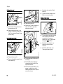
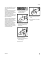
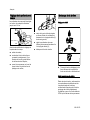
N Mount the bar and chain – see
instruction manual of basic
chainsaw.
N Push the guard (1) over the guide
bar and fit the screws (2).
N Slide the depth limiter (3) onto the
guard.
N Fit the star knob screw (4) with
washer (5).
N Tighten down the screws (2).
N Pull the depth limiter (3) forwards as
far as stop.
N Tighten down the star knob (4).
The cutting depth is infinitely variable
from a few millimeters to about 20 cm.
Before adjusting the cutting depth:
N Shut off the engine.
N Engage the chain brake by pushing
the hand guard (1) towards the bar
nose – this locks the chain in
position.
N Place the chainsaw on the ground,
put the heel of your right foot on the
rear hand guard and press down.
Mounting the depth limiter
3
2
4
5
3443BA030 KN
3
4
3443BA031 KN
Adjusting Cutting Depth

MS 461 R
English
4
N Grip the handle on top of the depth
limiter with your right hand and
loosen the star knob (2) with your
left hand.
N Set the depth limiter to the required
cutting depth (arrow) and tighten
down the star knob (2) firmly.
N Disengage the chain brake.
Adjusting the delivery rate
N Turn adjusting screw (on the bottom
of the machine) to the right as far as
it will go = maximum delivery rate
Chain lubricant
Because of the anticipated long periods
of disuse, a partly synthetic chain
lubricant, e. g., STIHL Chain and Bar
Lubricant.
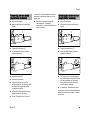
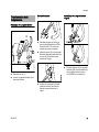
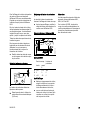
Removing the handlebar
N Remove the screws (1).
N Lift away the handlebar (2) to the
rear.
3443BA032 KN
2
Chain lubrication
147BA012 KN
E
Converting a chain saw
1
1
147BA005 KN
2
1
1

MS 461 R
English
5
Fitting the holder
N Coat inside of hole (a) with STIHL
OH 723 press fluid or washing-up
liquid.
N Push the holder (2) onto the wrap-
around handlebar so that the
recess (b) is as shown in the
illustration.
N Position the holder (2) with the
recess (b) as shown in the
illustration.
Assembling wrap-around handlebar
N Push bracket (3) onto center
strut (4) and secure to end (5) of
handlebar with M5x20 screw (6)
and washer (7).
Mounting wrap-around handlebar
N Slip the handlebar (b) over the saw
from the rear and bring it into
position.
N Fit the P6x32.5 screws (2).
N Insert and tighten down the existing
P6x19 screws (3).
N Fit the combination wrench in the
holder.
179BA039 KN
a
2
b
4
5
3
147BA006 KN
6
7

MS 461 R
English
6
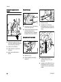
Cutting attachment
N Unscrew the nuts (1) and remove
the sprocket cover (2).
N Remove the bar and chain – see
chapter on "Mounting the Bar and
Chain" in instruction manual of saw
you are using.
Installing the guard plate
N Remove the screw (1) and nut (2).
N Take out the screw (3).
N Remove the spiked bumper (4) and
chain catcher (5).
N Take out the screw (6).
N Coat screw (7) from conversion kit
with Loctite 243 or equivalent
adhesive and install.
N Fit the guard plate (8) with screw (1)
and nut (2).
N Coat the M5x12 screw (9) from
conversion kit with Loctite 243 or
equivalent adhesive.
N Fit the screw (9) with washer (10) –
washer is supplied only with a
slotted guard plate and is required
only in such a case.
N Mount the chain catcher (5) with
screw (3).
N Tighten down the screws and nut
firmly in a crosswise pattern.
Chain sprocket cover
N To mount the bar and chain, use the
chain sprocket cover from the
conversion kit – the spacer
washers (2), cover (3) and spiked
bumper (4) must be fitted.
N Mount the bar and chain – see
instruction manual of basic
chainsaw.
N Mount the depth limiter – see
"Mounting the depth limiter".
1
1
147BA008 KN
2
10
3
1
9
2
5
8
147BA017 KN

MS 461 R
English
7
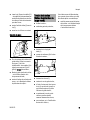
N Shut off the engine.
N Wear work gloves to protect your
hands.
N Loosen the star knob (1).
N Slide the depth limiter (2) back
against the engine.
N Loosen the nuts (3).
N Hold the bar nose up.
N Use a screwdriver to turn the
tensioning screw (4) clockwise until
the chain fits snugly against the
underside of the bar.
N While still holding the bar nose up,
tighten down the nuts firmly.
N Go to "Checking Chain Tension".
A new chain has to be retensioned more
often than one that has been in use for
some time.
N Check chain tension frequently –
see chapter on "Operating
Instructions" in instruction manual of
basic chainsaw.
N Shut off the engine.
N Wear work gloves to protect your
hands.
N Loosen the star knob (1).
N Slide the depth limiter (2) back
against the engine.
N The chain must fit snugly against
the underside of the bar and it must
still be possible to pull the chain
along the bar by hand when the
chain brake is released.
N If necessary, retension the chain.
A new chain has to be retensioned more
often than one that has been in use for
some time.
Tensioning the saw chain
(depth limiter installed)
1
3443BA033 KN
2
3
3
4
3443BA034 KN
Checking the chain tension
(depth limiter installed)
1
3443BA033 KN
2
3443BA035 KN

MS 461 R
English
8
N Check chain tension frequently –
see chapter on "Operating
Instructions" in instruction manual of
basic chainsaw.
N Adjust cutting depth.
Never use a dull or damaged saw chain
– this leads to increased physical strain,
increased vibration load, unsatisfactory
cutting results and increased wear.
N Clean the saw chain
N Check the saw chain for cracks and
damaged rivets
N Replace damaged or worn chain
components and adapt these parts
to the remaining parts in terms of
shape and level of wear – rework
accordingly
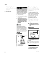
WARNING
Compliance with the angles and
dimensions listed below is absolutely
necessary. An improperly sharpened
saw chain – especially depth gauges
that are too low – can lead to increased
kickback tendency of the chain saw –
risk of injury!
Saw chain 36 RDR
A Sharpening angle 15°
B Side plate angle 85°
To sharpen the carbide-tipped saw
chain, use only the USG universal
sharpener with a diamond wheel. When
doing so, proceed according to the USG
Instruction Manual.
The angles must be identical for all
cutters in the saw chain. Varying angles:
Rough, uneven running of the saw
chain, increased wear – even to the
point of saw chain breakage.
All cutters must be equally long.
With varying cutter lengths, the cutter
heights also vary and cause rough
running of the saw chain and chain
breakage.
N All cutters must be ground down
equal to the length of the shortest
cutter
Depth gauge setting
The depth gauge determines the chip
thickness.
a Required distance between depth
gauge and cutting edge (0.65 mm)
Lowering the depth gauges
The depth gauge setting is lowered
when the cutter is sharpened.
Maintaining and Sharpening
the Saw Chain

MS 461 R
English
9
N Check the depth gauge setting after
each sharpening and grind with the
USG
Settings on the USG sharpener
Saw chain 36 RDR
After sharpening
N Clean the saw chain thoroughly,
removing any chips or dust –
lubricate the saw chain thoroughly
N In the event of extended periods of
disuse, store saw chains in cleaned
and oiled condition
Repair
The saw chain can be repaired with
NG 3, NG 4, NG 5 and NG 7.
With the saw chain 36 RDR, cutters, tie
straps, 3-humped drive links, and drive
links can be unriveted and riveted.
Cutter Depth gauge
right left
A +10 +10 +40
B0 0 0
C+15 -15 0
-
+
-
-
A
B
C
523BA077 KN
+
+

MS 461 R
English
10
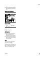
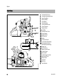
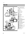
1 Carburetor Box Cover
2 Carburetor Adjusting Screws
3 Spark Plug Boot
4 Wrench Holder
5 Chain Brake
6 Chain Sprocket
7 Chain Sprocket Cover
8 Chain Tensioner
9 Bumper Spike
10 Guide Bar
11 Oilomatic Saw Chain
12 Chain Catcher
13 Splatter Shield
14 Oil Filler Cap
15 Muffler
16 Front Hand Guard
17 Front Handle (Handlebar)
18 Decompression Valve –
(Automatically Resetting)
19 Starter Grip
20 Fuel Filler Cap
21 Master Control Lever
22 Throttle Trigger
23 Rear Handle
24 Throttle Trigger Lockout
25 Rear Hand Guard
26 Depth Limiter
27 Star Knob
28 Bow Grip
# Serial Number
Main Parts
18
28
5
12
24
27
#
6
8
9
1
2
3
4
11
10
7
14
15
16
17
19
20
21
22
23
25
13
3443BA036 KN
26

MS 461 R
English
11
Definitions
1 Carburetor Box Cover
Covers the air filter and the
carburetor.
2 Carburetor Adjusting Screws
For tuning the carburetor.
3 Spark Plug Boot
Connects the spark plug with the
ignition lead.
4 Wrench Holder
To hold the wrench.
5Chain Brake
A device to stop the rotation of the
chain. Is activated in a kickback
situation by the operator's hand or
by inertia.
6 Chain Sprocket
The toothed wheel that drives the
saw chain.
7 Chain Sprocket Cover
Covers the clutch and chain
sprocket.
8 Chain Tensioner
Permits precise adjustment of chain
tension.
9Bumper Spike
Toothed stop for holding saw steady
against wood.
10 Guide Bar
Supports and guides the saw chain.
11 Oilomatic Saw Chain
A loop consisting of cutters, tie
straps and drive links.
12 Chain Catcher
Helps to reduce the risk of operator
contact by a chain when it breaks or
comes off the bar.
13 Splatter Shield
Helps to shield the crankcase and
the muffler from cutting debris.
14 Oil Filler Cap
For closing the oil tank.
15 Muffler
Reduces engine exhaust noises
and diverts exhaust gases away
from operator.
16 Front Hand Guard
Provides protection against
projecting branches and helps
prevent left hand from touching the
chain if it slips off the handlebar. It
also serves as the lever for chain
brake activation.
17 Front Handle (Handlebar)
Handlebar for the left hand at the
front of the saw.
18 Decompression Valve –
(Automatically Resetting)
Releases compression pressure to
make starting easier – when
activated.
19 Starter Grip
The grip of the pull starter, for
starting the engine.
20 Fuel Filler Cap
For closing the fuel tank.
21 Master Control Lever
Lever for choke control, starting
throttle, run and stop switch
position.
22 Throttle Trigger
Controls the speed of the engine.
23 Rear Handle
The support handle for the right
hand, located at the rear of the saw.
24 Throttle Trigger Lockout
Must be depressed before the
throttle trigger can be activated.
25 Rear Hand Guard
Gives added protection to
operator's right hand.
26 Depth Limiter
For adjusting the cutting depth of
the cutting attachment to limit the
depth of entry into material.
27 Star Knob
Locks depth limiter in selected
position.
28 Bow Grip
For adjusting the depth limiter.
Guide Bar Nose
The exposed end of the guide bar.
(not illustrated, see chapter
"Tensioning the Saw Chain".
Clutch
Couples engine to chain sprocket
when engine is accelerated beyond
idle speed. (not illustrated)
Anti-Vibration System
The anti-vibration system includes a
number of anti-vibration elements
designed to reduce the
transmission of vibrations created
by the engine and cutting
attachment to the operator's hands.
(not illustrated)

MS 461 R
English
12
Observe all country-specific waste
disposal rules and regulations.
STIHL products must not be thrown in
the garbage can. Take the product,
accessories and packaging to an
approved disposal site for environment-
friendly recycling.
Contact your STIHL servicing dealer for
the latest information on waste disposal.
Disposal
000BA073 KN

Notice d'emploi d'origineImprimé sur papier blanchi sans chlore
L'encre d'imprimerie contient des huiles végétales, le papier
est recyclable.
© ANDREAS STIHL AG & Co. KG, 2019
0458-180-8221-A. VA2.A19.
0000006424_004_F
MS 461 R
français
13
La présente Notice d'emploi est protégée par des droits d'auteur. Tous droits réservés, en particulier tout droit de copie, de tra-
duction et de traitement avec des systèmes électroniques quelconques.
Table des matières
Chère cliente, cher client,
nous vous félicitons d'avoir choisi un
produit de qualité de la société STIHL.
Ce produit a été fabriqué avec les
procédés les plus modernes et les
méthodes de surveillance de qualité les
plus évoluées. Nous mettons tout en
œuvre pour que cette machine vous
assure les meilleurs services, de telle
sorte que vous puissiez en être
parfaitement satisfait.
Pour toute question concernant cette
machine, veuillez vous adresser à votre
revendeur ou directement à
l'importateur de votre pays.
Dr. Nikolas Stihl
Indications concernant la présente
Notice d'emploi 14
Prescriptions de sécurité 14
Montage du limiteur de profondeur
de coupe 15
Réglage de la profondeur de coupe 16
Graissage de la chaîne 16
Transformation de la tronçonneuse 17
Tension de la chaîne (limiteur de
profondeur de coupe monté) 19
Contrôle de la tension de la chaîne
(limiteur de profondeur de coupe
monté) 20
Entretien et affûtage de la chaîne 20
Principales pièces 22
Mise au rebut 24

MS 461 R
français
14
Repérage des différents types de textes
AVERTISSEMENT
Avertissement contre un risque
d'accident et de blessure ainsi que de
graves dégâts matériels.
AVIS
Avertissement contre un risque de
détérioration de la machine ou de
certains composants.
Développement technique
La philosophie de STIHL consiste à
poursuivre le développement continu de
toutes ses machines et de tous ses
dispositifs ; c'est pourquoi nous devons
nous réserver tout droit de modification
de nos produits, en ce qui concerne la
forme, la technique et les équipements.
On ne pourra donc en aucun cas se
prévaloir des indications et illustrations
de la présente Notice d'emploi à l'appui
de revendications quelconques.
La tronçonneuse d'intervention rapide
STIHL est spécialement conçue pour les
services de secours et de sauvetage
(par ex. pompiers, services d'assistance
technique, services d'intervention dans
les zones sinistrées etc.).
La tronçonneuse d'intervention rapide
STIHL ne doit être utilisée, pour des
travaux de sauvetage, que par des
personnes dotées d'une formation
particulière et bien entraînées. En effet,
l'utilisateur ne doit pas seulement savoir
manier une tronçonneuse, mais il doit
être aussi capable d'évaluer les risques
compte tenu des circonstances
particulières.
L'utilisation de la tronçonneuse
d'intervention rapide STIHL exige
l'application de techniques de travail
particulières. Le fait de ne pas respecter
ces prescriptions entraîne
inévitablement l'accroissement des
risques d'accident, tant pour l'utilisateur
que pour les personnes à sauver.
La présente Notice d'emploi vient
compléter la Notice d'emploi standard
de la tronçonneuse de base. Elle décrit
les différences par rapport à la Notice
d'emploi standard.
Avant la première mise en service, il faut
lire attentivement les deux Notices
d'emploi.
Le fait de ne pas respecter les
prescriptions de sécurité peut présenter
un danger de mort.
En faisant le plein du réservoir à
carburant, tenir compte du fait que la
manipulation du carburant présente un
risque d'incendie.
Le dispositif de coupe spécial (chaîne à
dents garnies de plaquettes de carbure)
coupe les tôles minces, le carton bitumé,
la maçonnerie légère, les matériaux
isolants, les panneaux de revêtement
des toitures, le verre (par ex. le verre de
sécurité des trains ICE/TGV), les clous,
etc.
En cas de dégagement de poussière, de
même que pour couper du verre, il faut
porter un masque antipoussière ou un
masque respiratoire.
Avant d'entreprendre le travail, il faut
impérativement mettre l'équipement de
protection individuel décrit dans la
Notice d'emploi de la tronçonneuse de
base. Porter en plus des lunettes de
protection et une visière protégeant le
visage.
Les éclats et débris projetés au cours de
la coupe présentent un grand risque de
blessure. Ils peuvent avoir des arêtes
vives et, en raison de leur plus haute
densité, ils peuvent développer une
énergie cinétique supérieure à celle de
copeaux de bois.
Dans la lutte contre les incendies, le
limiteur de profondeur de coupe permet
de découper avec précision des
ouvertures d'échappement d'air dans
les toitures ou les panneaux de
revêtement, afin de soutenir la
ventilation forcée.
Étant donné la méthode de travail
particulière appliquée dans ce genre
d'interventions, c'est-à-dire la coupe
Indications concernant la
présente Notice d'emploi
Prescriptions de sécurité

MS 461 R
français
15
avec le nez du guide-chaîne, un grand
risque de rebond (kick-back) peut se
présenter.
Lors de toute opération de tronçonnage,
il faut observer les caractéristiques
statiques (résiduelles) de la construction
sciée, tout particulièrement lors
d'interventions sur une toiture, pour que
personne ne risque de tomber et que la
toiture ne s'effondre pas.
Cette tronçonneuse peut être également
utilisée pour la recherche de foyers
d'incendie, en particulier en cas de feux
couvants, dans les combles de
bâtiments industriels ou commerciaux.
Le filtre HD2 assure une très bonne
filtration de l'air aspiré même dans les
conditions extrêmes que l'on rencontre
lors d'interventions rapides.
N Monter le guide-chaîne et la chaîne
– voir Notice d'emploi de la
tronçonneuse de base ;
N glisser le fourreau (1) par-dessus le
guide-chaîne et visser les vis (2)
sans les serrer ;
N glisser le coulisseau (3) ;
N engager la vis à poignée étoile (4)
avec la rondelle (5) ;
N serrer les vis (2) ;
N tirer le coulisseau (3) à fond vers
l'avant ;
N serrer fermement la vis à poignée
étoile (4).
Montage du limiteur de
profondeur de coupe
3
2
4
5
3443BA030 KN
3
4
3443BA031 KN

MS 461 R
français
16
La profondeur de coupe peut être réglée
en continu, de quelques millimètres
jusqu'à env. 20 cm.
Avant toute modification du réglage de
la profondeur de coupe :
N arrêter le moteur ;
N enclencher le frein de chaîne en
poussant le protège-main (1) en
direction du nez du guide-chaîne –
la chaîne est alors bloquée ;
N poser la tronçonneuse sur le sol et
poser le talon du pied droit sur le
protège-main arrière ;
N saisir de la main droite la poignée
en forme d'étrier du coulisseau et
desserrer la vis à poignée étoile (2)
de la main gauche ;
N régler la profondeur de coupe
(flèche) puis resserrer fermement la
vis à poignée étoile (2) ;
N débloquer le frein de chaîne.
Réglage du débit
N Tourner le boulon de réglage (sur la
face inférieure de la machine) à
fond vers la droite = débit maximal.
Huile de graissage de chaîne
Étant donné sa fonction, cette machine
sera probablement arrêtée durant de
longues périodes et il est donc
recommandé d'employer de l'huile de
graissage de chaîne partiellement
synthétique, par ex. de l'huile adhésive
STIHL pour chaînes de tronçonneuses.
Réglage de la profondeur de
coupe
3443BA032 KN
2
Graissage de la chaîne
147BA012 KN
E

MS 461 R
français
17
Démontage de la poignée tubulaire
N Desserrer les vis (1) ;
N enlever la poignée tubulaire (2) en
tirant vers l'arrière.
Montage du support
N Humecter la paroi de l'orifice (a)
avec du produit antifriction STIHL
Press Fluid OH 723 ou avec du
produit pour laver la vaisselle ;
N glisser le support (2) sur la poignée
tubulaire intégrale de telle sorte que
le creux (b) soit orienté comme
montré sur la figure ;
N positionner le support (2) de telle
sorte que le creux (b) se trouve
disposé comme montré sur la
figure.
Assemblage de la poignée tubulaire
intégrale
N Emboîter l'équerre (3) sur la partie
centrale (4) et visser l'extrémité (5)
de la poignée tubulaire avec la
vis (6) M5x20 et la rondelle (7).
Transformation de la
tronçonneuse
1
1
147BA005 KN
2
1
1
179BA039 KN
a
2
b
4
5
3
147BA006 KN
6
7

MS 461 R
français
18
Montage de la poignée tubulaire
intégrale
N Présenter la poignée tubulaire (1)
par l’arrière, la glisser par-dessus la
tronçonneuse et la positionner ;
N visser les vis (2) P6x32,5 ;
N visser et serrer la vis (3) P6x19
(d'origine) ;
N glisser la clé multiple dans le
support.
Dispositif de coupe
N Dévisser les écrous (1) et enlever le
couvercle de pignon (2) ;
N enlever le guide-chaîne et la chaîne
(voir Notice d'emploi de la
tronçonneuse de base « Montage
du guide-chaîne et de la chaîne ».
Montage de la tôle de protection
N Dévisser la vis (1) et l'écrou (2) ;
N dévisser la vis (3) ;
N enlever la griffe (4) et l'arrêt de
chaîne (5) ;
N dévisser la vis (6) ;
N humecter la vis (7) du kit de
transformation avec du Loctite 243
ou de la colle de même qualité et la
visser ;
N mettre en place la tôle de
protection (8) avec la vis (1) et
l'écrou (2) ;
N humecter la vis (9) M5x12 du kit de
transformation et la vis (3) avec du
Loctite 243 ou de la colle de même
qualité ;
1
1
147BA008 KN
2
10
3
1
9
2
5
8
147BA017 KN
La page est en cours de chargement...
La page est en cours de chargement...
La page est en cours de chargement...
La page est en cours de chargement...
La page est en cours de chargement...
La page est en cours de chargement...
La page est en cours de chargement...
La page est en cours de chargement...
-
 1
1
-
 2
2
-
 3
3
-
 4
4
-
 5
5
-
 6
6
-
 7
7
-
 8
8
-
 9
9
-
 10
10
-
 11
11
-
 12
12
-
 13
13
-
 14
14
-
 15
15
-
 16
16
-
 17
17
-
 18
18
-
 19
19
-
 20
20
-
 21
21
-
 22
22
-
 23
23
-
 24
24
-
 25
25
-
 26
26
-
 27
27
-
 28
28


STIHL MS 461 R Manuel utilisateur
- Catégorie
- Jouets
- Taper
- Manuel utilisateur
dans d''autres langues
- English: STIHL MS 461 R User manual
Documents connexes
-
STIHL MS 192 T Manuel utilisateur
-
-
-
STIHL GS 461 Manuel utilisateur
-
STIHL MS 231 Manuel utilisateur
-
-
-
-
STIHL MS 390 Manuel utilisateur