Tripp Lite WWSS1332C Le manuel du propriétaire
- Taper
- Le manuel du propriétaire

1
Owner’s Manual
Single-Display Sit-Stand
Desk-Mount Workstation
Model: WWSS1332C
1111 W. 35th Street, Chicago, IL 60609 USA • www.tripplite.com/support
Copyright © 2017 Tripp Lite. All rights reserved.
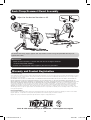
CAUTION: DO NOT EXCEED MAXIMUM LISTED WEIGHT CAPACITY
(17.6 lb. / 8 kg). SERIOUS INJURY OR PROPERTY DAMAGE MAY OCCUR!
PROTECT YOUR INVESTMENT!
Register your product for quicker service and ultimate peace of mind.
You could also win an ISOBAR6ULTRA surge protector—a $100 value!
www.tripplite.com/warranty
Español 10 • Français 19 • Русский 28 • Deutsch 37
17-09-135-933778.indb 1 10/31/2017 11:49:30 AM

2
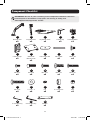
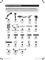
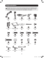
Component Checklist
IMPORTANT: Ensure all parts according to the component checklist have been
received prior to installation. If any parts are missing or faulty, visit
www.tripplite.com/support for service.
A
F
K
P
U
B
G
L
Q
D
I
N
S
E
J
O
T
W
C
H
M
R
V
Bracket Arm
x1
Cable Clamp
x1
M6 x 12
x4
M5 x 16
x4
4 mm Hex Key
x1
Support Mast
x1
Grommet
Mount Plate
x1
M8 x 25
x2
5 x 12 x 1
x4
Keyboard Shelf
x1
Pressure Plate
x2
M4 x 12
x4
D8
x2
6 mm Hex Key
x1
Clamp Top
x1
M8 x 105
x2
M5 x 12
x4
8 x 5 Spacer
x4
Clamp Bottom
x1
M6 x 10
x4
M4 x 16
x4
M8
x2
Wrench
x1
17-09-135-933778.indb 2 10/31/2017 11:49:30 AM

3
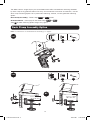
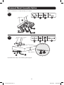
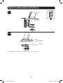
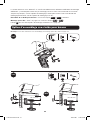
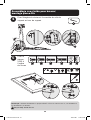
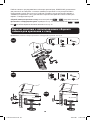
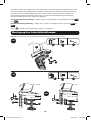
Desk Clamp Assembly Option
1a-1
1a-2
or
Note: For instructions on Grommet Mount Assembly, go to page 5.
D
E
U
U
J
K
x4
x4
U
D
J
A
E
K
U
3/8 to 2”
(10 to 55 mm)
1 1/2 to 3 9/16”
(40 to 92 mm)
The WWSS1332C Single-Display Sit-Stand Workstation offers two different mounting methods:
by desk clamp or by grommet mount. For easy and convenient installation and removal, use the
desk clamp mounting option. For a permanent mounting solution, use the grommet mounting
option.
Desk Clamp Assembly – Follow steps
1a-1
to
1a-4
below.
Grommet Mount – Go to page 5 and follow steps
1b-1
to
1b-2
.
Step
2
for both mounting options begins on page 6.
17-09-135-933778.indb 3 10/31/2017 11:49:30 AM

4
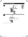
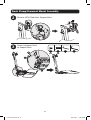
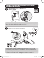
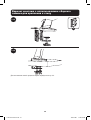
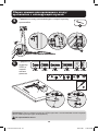
Desk Clamp Assembly Option
1a-3
1a-4
F
F
To proceed with step 2 of assembly, go to page 6.
17-09-135-933778.indb 4 10/31/2017 11:49:30 AM

5
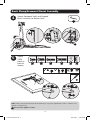
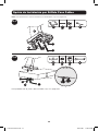
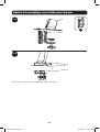
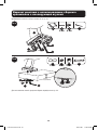
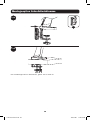
Grommet Mount Assembly Option
1b-2
1b-1
G
U
JI
x4x2
H
W
TR
x2 x2 x2
A
U
J
G
I
W
H
R
T
3/8 to 3”
(10 to 80 mm)
To proceed with step 2 of assembly, go to page 6.
Note: For instructions on Clamp Assembly, go to page 3.
17-09-135-933778.indb 5 10/31/2017 11:49:30 AM

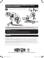
6
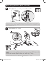
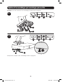
2
3
Remove VESA Plate from Support Mast
Attach Keyboard Shelf
to Support Mast
K
V
UL
x2 x2
U
V
K
L
Desk Clamp/Grommet Mount Assembly
17-09-135-933778.indb 6 10/31/2017 11:49:30 AM

7
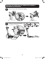
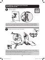
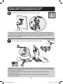
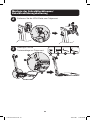
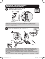
Desk Clamp/Grommet Mount Assembly
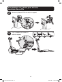
4
Attach Keyboard Shelf and Support
Mast Assembly to Bracket Arm
Attach
VESA
plate to
back of
display
U
U
U
3/16” (5 mm)
5
TV
TV
TV
TV
M
P Q S
ON
x4 x4 x4 x4x4x4
M
ON
Q Q
S
P
or or
Note: Firmly secure the VESA plate to the display using the appropriate screws, washers and
spacers (if necessary).
Do not over-tighten screws.
17-09-135-933778.indb 7 10/31/2017 11:49:30 AM

8
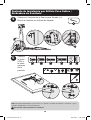
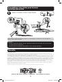
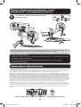
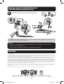
Desk Clamp/Grommet Mount Assembly
6
Slide VESA plate and Display on to the Support Mast
Adjust Bracket Arm tension
V
7
V
Using an assistant or mechanical lifting equipment, lift the display with attached VESA plate.
Slide the VESA plate over the Support Mast bracket. Reattach the top knob to secure the VESA
mount (removed in step 1).
Keep the bracket arm level during tension adjustment. You may need to slightly loosen or tight-
en the adjustment screw using the provided 6 mm Hex Key, depending on the weight of display
installed.
If display settles on its own, rotate adjustment screw towards the “+” symbol.
If display rises on its own, rotate adjustment screw towards the “-” symbol.
17-09-135-933778.indb 8 10/31/2017 11:49:31 AM

9
Desk Clamp/Grommet Mount Assembly
8
Adjust to the desired location or tilt
+4° -
4°
+15°
-15°
U
V
To correct the tilting angle, tighten the adjustment screws using the provided Hex Keys (or
tighten the knob).
Maintenance
• Check that the bracket is secure and safe to use at regular intervals
(at least every three months).
• Please visit www.tripplite.com/support if you have any questions.
V
U
Warranty and Product Registration
5-Year Limited Warranty
Seller warrants this product, if used in accordance with all applicable instructions, to be free from original defects in material and workmanship for a period
of 5 years from the date of initial purchase. If the product should prove defective in material or workmanship within that period, Seller will repair or replace
the product, in its sole discretion.
THIS WARRANTY DOES NOT APPLY TO NORMAL WEAR OR TO DAMAGE RESULTING FROM ACCIDENT, MISUSE, ABUSE OR NEGLECT. SELLER MAKES NO
EXPRESS WARRANTIES OTHER THAN THE WARRANTY EXPRESSLY SET FORTH HEREIN. EXCEPT TO THE EXTENT PROHIBITED BY APPLICABLE LAW, ALL
IMPLIED WARRANTIES, INCLUDING ALL WARRANTIES OF MERCHANTABILITY OR FITNESS, ARE LIMITED IN DURATION TO THE WARRANTY PERIOD SET FORTH
ABOVE; AND THIS WARRANTY EXPRESSLY EXCLUDES ALL INCIDENTAL AND CONSEQUENTIAL DAMAGES. (Some states do not allow limitations on how
long an implied warranty lasts, and some states do not allow the exclusion or limitation of incidental or consequential damages, so the above limitations or
exclusions may not apply to you. This warranty gives you specific legal rights, and you may have other rights which vary from jurisdiction to jurisdiction).
WARNING: The individual user should take care to determine prior to use whether this device is suitable, adequate or safe for the use intended. Since
individual applications are subject to great variation, the manufacturer makes no representation or warranty as to the suitability or fitness of these devices
for any specific application.
PRODUCT REGISTRATION
Visit www.tripplite.com/warranty today to register your new Tripp Lite product. You’ll be automatically entered into a drawing for a chance to win a FREE
Tripp Lite product!* * No purchase necessary. Void where prohibited. Some restrictions apply. See website for details.
Tripp Lite has a policy of continuous improvement. Specifications are subject to change without notice.
1111 W. 35th Street, Chicago, IL 60609 USA • www.tripplite.com/support
17-09-135-933778.indb 9 10/31/2017 11:49:31 AM

10
Manual del Propietario
Estación de Trabajo de
Altura Variable para Una
Pantalla para Instalación
en Escritorio
Modelo: WWSS1332C
1111 W. 35th Street, Chicago, IL 60609 USA • www.tripplite.com/support
Copyright © 2017 Tripp Lite. Todos los derechos reservados.
PRECAUCIÓN: NO EXCEDA LA CAPACIDAD MÁXIMA DE CARGA INDICADA (8 kg).
¡PUEDE OCURRIR UNA LESIÓN SEVERA O DAÑO A LA PROPIEDAD!
English 1 • Français 19 • Русский 28 • Deutsch 37
17-09-135-933778.indb 10 10/31/2017 11:49:32 AM

11
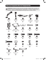
Lista de Comprobación de Componentes
IMPORTANTE: Asegúrese antes de instalar, de haber recibido todas las partes de
acuerdo a la lista de comprobación de componentes. Si faltase cualquier parte o
estuviese dañada, visite www.tripplite.com/support para solicitar servicio.
A
F
K
P
U
B
G
L
Q
D
I
N
S
E
J
O
T
W
C
H
M
R
V
Brazo de
Soporte
x1
Abrazadera de
Cable
x1
M6 x 12
x4
M5 x 16
x4
Llave
Hexagonal de
4 mm
x1
Mástil de
Soporte
x1
Placa para
Instalación con
Orificio Pasa Cables
x1
M8 x 25
x2
5 x 12 x 1
x4
Repisa para
Teclado
x1
Placa de
Presión
x2
M4 x 12
x4
D8
x2
Llave
Hexagonal de
6 mm
x1
Parte
Superior de la
Abrazadera
x1
M8 x 105
x2
M5 x 12
x4
Espaciador de
8 x 5
x4
Parte
Inferior de la
Abrazadera
x1
M6 x 10
x4
M4 x 16
x4
M8
x2
Llave
x1
17-09-135-933778.indb 11 10/31/2017 11:49:32 AM

12
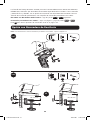
Opción con Abrazadera de Escritorio
1a-1
1a-2
o
Nota: Para instrucciones sobre la instalación por Orificio Pasa Cables, vaya a la página 14.
D
E
U
U
J
K
x4
x4
U
D
J
A
E
K
U
10 a 55 mm
40 a 92 mm
La Estación de Trabajo de Altura Variable para Una Pantalla WWSS1332C ofrece dos diferentes
métodos de instalación: por abrazadera de escritorio o por Orificio Pasa Cables. Para instalación
y remoción fácil y cómoda, use la opción de instalación con abrazadera de escritorio. Para una
solución de instalación permanente, use la opción de instalación por Orificio Pasa Cables.
Ensamble con Abrazadera de Escritorio – Siga los pasos
1a-1
a
1a-4
siguientes.
Instalación por Orificio Pasa Cables – Vaya a la página X y siga los pasos
1b-1
a
1b-2
.
Paso
2
para ambas opciones de instalación inicie en la página 15.
17-09-135-933778.indb 12 10/31/2017 11:49:32 AM

13
Opción con Abrazadera de Escritorio
1a-3
1a-4
F
F
Para proceder con el paso 2 del ensamble, vaya a la página 15.
17-09-135-933778.indb 13 10/31/2017 11:49:33 AM

14
Opción de Instalación por Orificio Pasa Cables
1b-2
1b-1
G
U
JI
x4x2
H
W
TR
x2 x2 x2
A
U
J
G
I
W
H
R
T
10 a 88 mm
Para proceder con el paso 2 del ensamble, vaya a la página15.
Nota: Para instrucciones sobre la instalación por abrazadera, vaya a la página 12.
17-09-135-933778.indb 14 10/31/2017 11:49:33 AM

15
2
3
Retire la Placa VESA del Mástil de Soporte
Coloque la Repisa para Teclado
en el Mástil de Soporte
K
V
UL
x2 x2
U
V
K
L
Conjunto de Instalación por Orificio Pasa Cables /
Abrazadera de Escritorio
17-09-135-933778.indb 15 10/31/2017 11:49:33 AM

16
Conjunto de Instalación por Orificio Pasa Cables /
Abrazadera de Escritorio
4
Coloque el Conjunto de la Repisa para Teclado y el
Mástil de Soporte en el Brazo de Soporte
Coloque
la placa
VESA a
la parte
posterior
de la
pantalla
U
U
U
5 mm
5
TV
TV
TV
TV
M
P Q S
ON
x4 x4 x4 x4x4x4
M
ON
Q Q
S
P
o o
Nota: Asegure firmemente la placa VESA a la pantalla usando los tornillos, arandelas y espa-
ciadores apropiados (si fuera necesario).
No apriete excesivamente los tornillos.
17-09-135-933778.indb 16 10/31/2017 11:49:33 AM

17
6
Deslice la placa VESA y la Pantalla en el
Mástil de Soporte
Ajuste la tensión del Brazo de Soporte
V
7
V
Usando un ayudante o equipo de elevación mecánico, levante la pantalla con la placa VESA
acoplada. Deslice la placa VESA sobre la Ménsula del Mástil de Soporte. Reinstale la perilla
superior para sujetar el soporte VESA (retirados en el paso 1).
Mantenga nivelado el brazo del soporte de pared durante el ajuste de la tensión. Puede
necesitar apretar o aflojar ligeramente el tornillo de ajuste con la llave hexagonal de 6 mm
suministrada, dependiendo del peso de la pantalla instalada.
Si la pantalla se baja por sí misma, gire el tornillo de ajuste hacia el símbolo “+”.
Si la pantalla se levanta por sí misma, gire el tornillo de ajuste hacia el símbolo “-”.
Conjunto de Instalación por Orificio Pasa Cables /
Abrazadera de Escritorio
17-09-135-933778.indb 17 10/31/2017 11:49:33 AM

18
8
Ajuste a la posición o inclinación deseada
+4° -
4°
+15°
-15°
U
V
Para corregir el ángulo de inclinación, apriete el tornillo de ajuste usando las llaves
hexagonales suministradas (o apriete la perilla).
Mantenimiento
• Compruebe a intervalos regulares
(al menos cada tres meses) que el soporte esté seguro para usarse.
• Si tiene alguna pregunta, visite por favor a www.tripplite.com/support.
V
U
Garantía
Garantía Limitada por 5 Años
El vendedor garantiza este producto, si se usa de acuerdo con todas las instrucciones aplicables, de que está libre de defectos en material y mano de obra
por un período de 5 años a partir de la fecha de compra inicial. Si el producto prueba ser defectuoso en material o mano de obra dentro de ese período, el
vendedor reparará o reemplazará el producto a su entera discreción.
ESTA GARANTÍA NO APLICA AL DESGASTE NORMAL O A DAÑOS RESULTANTES DE ACCIDENTES, MAL USO, ABUSO O NEGLIGENCIA. EL VENDEDOR
NO OTORGA GARANTÍAS EXPRESAS DISTINTAS DE LA ESTIPULADA AQUÍ. EXCEPTO A LA EXTENSIÓN PROHIBIDA POR LA LEY APLICABLE, TODAS LAS
GARANTÍAS IMPLÍCITAS, INCLUYENDO TODAS LAS GARANTÍAS DE COMERCIALIZACIÓN O IDONEIDAD, ESTÁN LIMITADAS EN DURACIÓN AL PERÍODO DE
GARANTÍA ESTABLECIDO; Y ESTA GARANTÍA EXCLUYE EXPRESAMENTE TODOS LOS DAÑOS INCIDENTALES Y CONSECUENCIALES. (Algunos estados no
permiten limitaciones en cuanto al período de duración de una garantía y algunos estados no permiten la exclusión de limitación de daños incidentales o
consecuenciales, de modo que las limitaciones anteriores pueden no aplicar para usted. Esta garantía le otorga derechos legales específicos y usted puede
tener otros derechos que pueden variar de una jurisdicción a otra).
IMPORTANTE: Asegúrese antes de instalar, de haber recibido todas las partes de acuerdo a la lista de comprobación de componentes. Si faltase cualquier
parte o estuviese dañada, visite www.tripplite.com/support para solicitar servicio.
Tripp Lite tiene una política de mejora continua. Las especificaciones están sujetas a cambio sin previo aviso.
1111 W. 35th Street, Chicago, IL 60609 USA • www.tripplite.com/support
Conjunto de Instalación por Orificio Pasa Cables /
Abrazadera de Escritorio
17-09-135-933778.indb 18 10/31/2017 11:49:33 AM

19
Manuel de l’utilisateur
Station de travail à
montage sur bureau assis-
debout à un seul écran
Modèle : WWSS1332C
1111 W. 35th Street, Chicago, IL 60609 USA • www.tripplite.com/support
Droits d’auteur © 2017 Tripp Lite. Tous droits réservés.
MISE EN GARDE : NE PAS EXCÉDER LA CAPACITÉ PONDÉRALE MAXIMUM
INDIQUÉE (8 kg). DES BLESSURES GRAVES OU DES DOMMAGES MATÉRIELS
RISQUENT DE SE PRODUIRE!
English 1 • Español 10 • Русский 28 • Deutsch 37
17-09-135-933778.indb 19 10/31/2017 11:49:34 AM

20
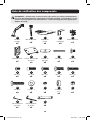
Liste de vérification des composants
IMPORTANT : Veuillez vous assurer d’avoir reçu toutes les pièces conformément
à la liste de vérification des composants avant de procéder à l’installation. Si des
pièces sont manquantes ou défectueuses, visitez www.tripplite.com/support pour
obtenir de l’aide.
A
F
K
P
U
B
G
L
Q
D
I
N
S
E
J
O
T
W
C
H
M
R
V
Bras du
support
x1
Bride de câble
x1
M6 x 12
x4
M5 x 16
x4
Clé hexagonale
de 4 mm
x1
Mât de support
x1
Plaque de montage
passe-fils
x1
M8 x 25
x2
5 x 12 x 1
x4
Étagère du
clavier
x1
Plaque de
pression
x2
M4 x 12
x4
D8
x2
Clé hexagonale
de 6 mm
x1
Bride
supérieure
x1
M8 x 105
x2
M5 x 12
x4
Entretoise
8 x 5
x4
Bride inférieure
x1
M6 x 10
x4
M4 x 16
x4
M8
x2
Clé
x1
17-09-135-933778.indb 20 10/31/2017 11:49:34 AM
La page est en cours de chargement...
La page est en cours de chargement...
La page est en cours de chargement...
La page est en cours de chargement...
La page est en cours de chargement...
La page est en cours de chargement...
La page est en cours de chargement...
La page est en cours de chargement...
La page est en cours de chargement...
La page est en cours de chargement...
La page est en cours de chargement...
La page est en cours de chargement...
La page est en cours de chargement...
La page est en cours de chargement...
La page est en cours de chargement...
La page est en cours de chargement...
La page est en cours de chargement...
La page est en cours de chargement...
La page est en cours de chargement...
La page est en cours de chargement...
La page est en cours de chargement...
La page est en cours de chargement...
La page est en cours de chargement...
La page est en cours de chargement...
La page est en cours de chargement...
-
 1
1
-
 2
2
-
 3
3
-
 4
4
-
 5
5
-
 6
6
-
 7
7
-
 8
8
-
 9
9
-
 10
10
-
 11
11
-
 12
12
-
 13
13
-
 14
14
-
 15
15
-
 16
16
-
 17
17
-
 18
18
-
 19
19
-
 20
20
-
 21
21
-
 22
22
-
 23
23
-
 24
24
-
 25
25
-
 26
26
-
 27
27
-
 28
28
-
 29
29
-
 30
30
-
 31
31
-
 32
32
-
 33
33
-
 34
34
-
 35
35
-
 36
36
-
 37
37
-
 38
38
-
 39
39
-
 40
40
-
 41
41
-
 42
42
-
 43
43
-
 44
44
-
 45
45


Tripp Lite WWSS1332C Le manuel du propriétaire
- Taper
- Le manuel du propriétaire
Documents connexes
-
Tripp Lite WorkWise WWSS1332W Le manuel du propriétaire
-
-
-
-
-
-
-
-
Tripp Lite DDR1026SD Le manuel du propriétaire
-