Astria Fireplaces DRT4240/45-OLD Instruction Sheet
- Catégorie
- Cheminées
- Taper
- Instruction Sheet
Ce manuel convient également à

GAS CONVERSION KIT FOR FIREPLACES WITH ELECTRONIC IGNITION
NATURAL GAS TO PROPANE GAS (ECOFLOW VALVE)
[FOR USE IN FIREPLACE MODELS LISTED IN TABLE 1 ON PAGE 2]
KIT COMPONENTS
Main Burner Orifice, Low-Rate Orifice, LP Regulator, Conversion
Sticker and Conversion Sticker Form (to be filled out and affixed by
installer)
REQUIRED TOOLS AND SUPPLIES
Safety Gloves, Adjustable Wrench, Channel Locks, Flat Blade
Screwdriver, 4mm Allen Wrench (for some pilot assemblies - see
Figure 6), 5/16” Nutdriver, Pipe Wrench, Pipe Joint Compound
or Teflon Tape
TURN OFF THE GAS SUPPLY TO THE APPLIANCE. DISCONNECT
ELECTRICAL POWER SUPPLY.
READ ALL THE STEPS BEFORE STARTING THE CONVERSION. IN-
STALLER NOTICE: THESE INSTRUCTIONS MUST BE LEFT WITH THE
APPLIANCE.
When installing gas components use pipe joint compound or
Teflon tape on all pipe fittings before installing (Do not use pipe
joint compounds on flare fittings).
NOTE: THE FIREPLACE MUST BE OFF AND COLD BEFORE PERFORM-
ING THE GAS CONVERSION.
ALL WARNINGS, PRECAUTIONS AND INSTRUCTIONS IN THE INSTAL-
LATION AND OPERATION MANUAL PROVIDED WITH THE APPLIANCE
APPLY TO THESE INSTRUCTIONS.
GENERAL INFORMATION
Gas conversion kits are available to adapt the fireplace from the
use of one type of gas to the use of another. These kits contain all
the necessary components needed to complete the task including
labeling that must be affixed to ensure safe operation.
WARNING
This conversion kit shall be installed by a qualified
service agency in accordance with the manufac-
turer's instructions and all applicable codes and
requirements of the authority having jurisdiction. If
the information in these instructions is not followed
exactly, a fire, explosion or production of carbon
monoxide may result causing property damage,
personal injury or loss of life. The qualified service
agency performing this installation is responsible
for the proper installation of this kit and assumes
responsibility for this conversion. The installation
is not proper and complete until the operation of the
converted appliance is checked as specified in the
manufacturers instructions supplied with the kit.
IMPORTANT LE CANADA SEULEMENT
La conversion devra être effectuée conformément aux
recommandations des autorités provinciales ayant
juridiction et conformément aux exigences du code
d'installation CAN/CSA B149.1.
IMPORTANT CANADA
The conversion shall be carried out in accordance with
the requirements of the provincial authorities having
jurisdiction and in accordance with the requirements
of the CAN/CSA B149.1 Installation code.
AVERTISSEMENT
Cet équipement de conversion sera installé par
une agence qualifiée de service conformément aux
instructions du fabricant et toutes exigences et codes
applicables de l'autorisés avoir la juridiction. Si
l'information dans cette instruction n'est pas suivie
exactement, un feu, explosion ou production de
protoxyde de carbone peut résulter le dommages
causer de propriété, perte ou blessure personnelle de
vie. L'agence qualifiée de service est esponsable de
l'installation propre de cet équipment. L'installation
n'est pas propre et compléte jusqu'à l'opération de
l'appareil converti est chéque suivant les critères
établis dans les instructions de propriétaire provi-
sionnées avec l'équipement.
ECOFLOW GAS CONVERSION KITS
P/N 900836-00
Rev. A, 09/2017
HEARTH PRODUCTS
KITS AND ACCESSORIES
IHP.us.com
900836-00A 1

IHP.us.com 900836-00A
2
Gas Conversion Kits, Natural Gas (NG) to Propane Gas (LP)
Cat. No. Model Ecoflow Electronic Model Fireplaces
F2904 GCK-SKT556151NP AltairDLX40-B, DRT4240-B
F2906 GCK-SKT526151NP AltairDLX45-B, DRT4245-B
F2896 GCK-SKT557051NP Altair40-B, DRT4040-B
F2900 GCK-SKT537051NP Altair45-B,DRT4045-B
Table 1
INSTALLING GAS CONVERSION KITS
CAUTION
The gas supply shall be shut OFF prior to discon-
necting the electrical power, before proceeding with
the conversion.
ATTENTION
Avant d’effecteur la conversion, coupez d’abord
l’alimentation en gaz, ensuite, coupez l’alimentation
electrique.
1. TURN OFF THE GAS SUPPLY TO THE FIREPLACE. Disconnect
power supply at the circuit breaker. Ensure fireplace is cold.
2. TURN OFF THE GAS SUPPLY TO THE FIREPLACE AND DIS-
CONNECT THE FLEX LINE AT THE ELBOW FITTING ON THE
REGULATOR INLET (SEE FIGURE 3).
3. Remove the barrier, facade, and glass door per instruction in the
Installation and Operation Manual.
4. Remove the lower control compartment door.
5. Remove the logs per instruction in the Installation and Operation
Manual. If necessary, remove the log grate. Exercise care so as
not to break the logs.
7. Perform the following conversion instructions:
IMPORTANT
The burner orifice provided in this kit are only for use
at elevations of 0 to 2,000 feet (610 M) in the USA
and 0 to 4,500 feet (0-1372 M) in Canada. At higher
elevations the BTU input must be de-rated by 4% for
every 1,000 feet (305 M) to maintain the proper ratio
of gas to air. If the installer must convert the unit to
adjust for varying altitudes, a deration information
sticker must be filled out by the installer and adhered
to the appliance at the time of the conversion. Contact
your local gas supplier for deration requirements for
your area.
GAS CONVERSION INSTRUCTIONS
IMPORTANT NOTE: When installing gas components use pipe joint com-
pound or Teflon tape on all pipe fittings before installing (ensure pro-
pane resistant compounds are used, do not use pipe joint compounds
on flare fittings).
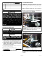
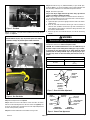
Step 1. Per instructions A through C below, remove the front and rear
burner assemblies.
A. Remove the screw from the Air Shutter Lever, that controls the rear
burner air shutter, per instructions in Figure 1A.
B. Disconnect the Air Shutter Arm from the Air Shutter Lever, per instruc-
tions in Figure 1B.
C. Remove the screws that secure the burner assemblies. Lift out burner
assemblies.
Figure 1A - REAR Air Shutter Adjustment Lever
Figure 1B - REAR Air Shutter Adjustment Arm
The adjustment lever for the rear air shutter is located in the lower control
compartment. Remove the hex screw that secures the lever as shown in
this picture.
Disconnect the rear air shutter arm from the lever.
Rear Air Shutter Adjustment Lever
Remove Hex Screw
REMOVE LEVER SCREW
Rear Air Shutter Arm
Lever
DISCONNECT SHUTTER ARM

900836-00A 3
IHP.us.com
Figure 2
Figure 3
Figure 4A
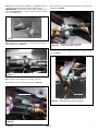
Step 3. Remove the low-rate orifice from the valve and replace with the
orifice supplied in kit. See Figure 3.
Step 2. Replace Front and Rear Burner Orifices (see Figure 2). Replace the
front and rear burner orifices with the orifices supplied in this kit.
IMPORTANT NOTE: The front and rear burner orifices are different sizes.
Refer to Table 5 on Page 7 for verification of proper front and rear burner
orifice sizes, supplied in kit.
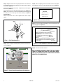
Step 4. Install the new LP regulator per instructions A through F.
A. Remove the screw shown below per instruction in Figure 4A.
Remove Phillips Screw
Remove this screw (located in the lower control compartment).
B. Pull entire valve, regulator and mounting bracket out of the firebox per
instruction in Figure 4B.
C. Remove the gas inlet line (that includes the pressure tap) per instruc-
tions in Figure 4C.
Figure 4B Pull entire valve, regulator and mounting
bracket out of firebox as shown here
Figure 4C
USING 2 WRENCHES, remove the gas inlet line
(that includes the pressure tap) as shown here.
Gas Inlet Line

IHP.us.com 900836-00A
4
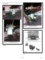
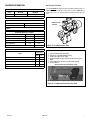
Figure 4F
Step 5. Pull the pilot hood straight up to remove and expose the pilot
orifice.
Elbow Fitting
Elbow Fitting
Flex Line
Regulator
Regulator
Pipe Nipple
Pipe Nipple
D. Remove the 4 screws that attach the valve mounting bracket per instruc-
tions in Figure 4D.
E. Place pipe wrench on pipe nipple and remove regulator per instructions
in Figure 4E.
F. Install new LP regulator by reversing steps A through E.
Figure 4D
Figure 4E
Remove the 4 screws (indicated by arrows) that attach the
valve mounting bracket as shown here.
Place pipe wrench on pipe nipple and
remove regulator as shown here.

900836-00A 5
IHP.us.com
Step 7. Reinstall pilot hood. See Figure 4.
Step 8. Retrieve the burner and hold the venturi tube above the orifice.
Place the shutter adjusting rod in the slot of the shutter arm (Figure 6). Set
the burner assembly into its position and secure the trapezoidal plate with
the two screws previously removed.
Step 9. Reinstall the baffle with the two baffle securing screws.
Figure 5 - Pilot Hood
Step 6. For propane - Turn pilot orifice clockwise until it stops (do not
tighten). See Figure 5.
Pilot Hood
WARNING
Never use an open flame to check for leaks.
Step 10. Reinstall the log set (Traditional Models) or glass media (Con-
temporary Models). See log set installation or glass media installation and
door Assembly installation in the installation and operation manual.
Step 11. Reinstall the glass door.
Step 12. Turn on gas supply and test for gas leaks, using a gas leak test
solution—also known as bubble leak solution.
NOTE: Using a soapy water solution is an effective leak test solution but
it is not recommended, because the soap residue that is left on the pipes/
fittings can result in corrosion over time.
A. Light the fireplace (refer to the lighting instructions label in the control
compartment).
B. Brush all joints and connections with the gas leak test solution to
check for leaks. If bubbles are formed, or gas odor is detected, turn
off the appliance. Either tighten or refasten the leaking connection, and
then retest as described above.
C. When the gas lines are tested and leak free, rinse off the leak testing
solution.
Figure 8 - Burner Flame Appearance
Figure 7 - Burner Air Shutter Adjustment
No Blue Flame
Center
Soot at
Flame Tip
Dark Orange
Flame
IMPROPERLY
BURNING FLAME
Soot above
Flame Tip No Soot at
Flame Tip
PROPERLY
BURNING FLAME
Semi-Transparent
Yellow Flame
Blue Flame
Center
Burner Air Shutter Gap
Models Propane Gas
All Models 1/8”
(3.2 mm)
Table 2
Air Shutter
Adjustment
Rod Down
(Fully-Open
Position)
Burner
Tube
Adjustment
Rod Up
(Fully-Closed
Position)
Adjustment
Set-Screw
Step 13. Adjust the burner air shutter per instructions in the Installation
and Operation manuals and Table 2 and Figures 6 and 7.
CAUTION: The air shutter should never be set so as to make the tips of
the flames sooty or create sooting on the viewing glass, logs, or media.
If soot begins to form after burning, the air shutter should be opened
gradually until the sooting condition stops. Gas quality and gas pres-
sure may vary, which can affect the burning characteristics of the ap-
pliance.
Figure 6 - Turn Pilot Orifice
Pilot Assemblies may vary. Type ‘A’ pilot will require a flat standard
screwdriver and Type ‘B’ pilot will require a 4mm allen wrench.
A
B

IHP.us.com 900836-00A
6
Figure 9 - Pilot Flame Appearance
Step 14. Relight the main burner. The lighting instructions can be found on
the lighting label in the control compartment. Verify proper burner ignition
and operation (Figure 8).
Inspect the pilot system for proper flame. The pilot flame should engulf the
flame sensor (Figure 9).
Using a manometer, test the inlet and manifold gas pressures (Tables 3–4,
Page 7). The inlet pressure is tested at elbow fitting removable plug and
the outlet pressure is tested at gas valve outlet test port (see Figures 13
and 14 on Page 7).
Always test pressures with the valve regulator control at the highest
setting.
Figure 10 - Ensure Proper Alignment Between Pilot And Burner
Pilot
Hood
Sensor
Ignitor
Igniter
Pilot Hood
Thermocouple
Pilot Hood
Thermocouple
Igniter
Step 15. Ensure the proper relationship of the pilot to the main burner as
shown in Figure 10.
Burner
Pilot Hood
Igniter
Flame
Sensor
Burner Ports
3/4” ± 1/16”
THIS APPLIANCE HAS BEEN CONVERTED TO:
INPUT BTU / HR - ##, ###
MANIFOLD PRESSURE - 10”
ORIFICE SIZE: ## (#.##”)
PROPANE GAS
Figure 11 - Affix Gas Conversion Sticker
Figure 12 - Fill Out and Affix Gas Conversion Form Sticker
Step 16. Affix the supplied gas conversion sticker next to the rating plate
label stating this unit has been converted to propane gas. See Figure 11.
Step 17. Fill out, then affix the supplied gas conversion form sticker next
to the rating plate. See Figure 12.
Step 18. Reinstall the facade, and barrier.
NOTE: A BARRIER DESIGNED TO REDUCE THE RISK OF BURNS
FROM HOT VIEWING GLASS SHALL BE USED DURING OPERA-
TION OF THIS FIREPLACE FOR THE PROTECTION OF CHILDREN
AND OTHER AT-RISK INDIVIDUALS.
“ THIS APPLIANCE HAS BEEN CONVERTED ON (MM/DD/YY)
________________ TO _____________ GAS WITH KIT NO.
_______________ BY (NAME AND ADDRESS OF ____________
_______________________________________ ORIGANIZATION
MAKING THIS CONVERSION), WHICH ACCEPTS THE
RESPONSIBILITY THAT THIS CONVERSION HAS BEEN
PROPERLY MADE.”
“CET APPAREIL ELAIT CONVERT SUR LE (MM/DD/YY)
________________ A _______________ GAZ AVEC
L’EQUIPEMENT NO. ____________________ PAR (NOM ET
ADRESSE_____________________________________________
D’ORGANISATION FAISANT CETTE CONVERSION), QUI ACCEPTE
LA RESPONSABILITE QUE CETTE CONVERSION A ETE FAITE
CORRECTEMENT”. LB-104682A

900836-00A 7
IHP.us.com
Inlet Gas Supply Pressure
Fuel # Minimum Maximum
Propane 11.0” WC (2.74 kPa) 13.0” WC (3.23 kPa)
Table 3
Manifold Gas Supply Pressure
Fuel # Pressure
Propane 10.0” WC / (2.49 kPa)
Table 4
Main Burner Orifice Sizes - Propane
Fireplace Model Front - Drill Size Rear - Drill Size
AltairDLX40-B, DRT4240-B #61 #55
AltairDLX45-B, DRT4245-B #61 #52
Altair40-B, DRT4040-B #70 #55
Altair45-B,DRT4045-B #70 #53
Table 5
BTU Input
Models
Propane Gas
High
Rate
Low-
rate
AltairDLX40-B, DRT4240-B 31,000 21,000
AltairDLX45-B, DRT4245-B 41,000 22,000
Altair40-B, DRT4040-B 25,000 18,000
Altair45-B,DRT4045-B 31,000 20,000
Table 6
REFERENCE INFORMATION Gas Pressure Test Points
The outlet manifold test gauge connection is provided on the valve stem (see
Figure 12). The inlet line gas pressure test point is shown in Figure 13. The
control valves have a 3/8” (10 mm) NPT thread inlet and outlet side of the
valve.
Figure 13 - Ecoflow Electronic Valve
Outlet Pressure
Test Point
Some parts have been removed for clarity
1/8” Inlet gas pressure ‘test point’ plug (in control compartment)
Testing Inlet Gas Pressure (Qualified Technicians Only):
1. Turn off gas shutoff valve and electrical.
2. Remove 1/8” plug (shown in diagram below).
3. Install an 1/8” nipple in place of plug.
4. Connect manometer to nipple, using an 1/8” NPT air hose nipple/
fitting.
5. Turn on shutoff valve and check for proper inlet gas pressure.
6. Reverse steps 1-5.
Figure 14 - Ecoflow Inlet Gas Pressure Test Point

Printed in U.S.A. © 2017 Innovative Hearth Products
P/N 900836-00 Rev. A 09/2017
IHP reserves the right to make changes at any time, without notice, in design, materials, specifica-
tions, prices and also to discontinue colors, styles and products. Consult your local distributor
for fireplace code information.
1508 Elm Hill Pike, Suite 108 • Nashville, TN 37210
-
 1
1
-
 2
2
-
 3
3
-
 4
4
-
 5
5
-
 6
6
-
 7
7
-
 8
8


Astria Fireplaces DRT4240/45-OLD Instruction Sheet
- Catégorie
- Cheminées
- Taper
- Instruction Sheet
- Ce manuel convient également à
dans d''autres langues
- English: Astria Fireplaces DRT4240/45-OLD
Documents connexes
-
Astria Fireplaces Scorpio CD Instruction Sheet
-
-
-
-
-
-