
GAS CONVERSION KIT FOR FIREPLACES WITH ELECTRONIC IGNITION - NATURAL GAS TO PROPANE GAS
[FOR USE IN FIREPLACE MODELS BARCELONA LIGHTS™ AND VRE4600 SERIES]
REQUIRED TOOLS AND SUPPLIES
Flat Bladed Screwdriver
Needle Nose Pliers
Pipe Joint Compound or Teflon Tape
Gas Leak Test Solution
TURN OFF THE GAS SUPPLY TO THE APPLIANCE. DISCONNECT
ELECTRICAL POWER SUPPLY.
READ ALL THE STEPS BEFORE STARTING THE CONVERSION. IN-
STALLER NOTICE: THESE INSTRUCTIONS MUST BE LEFT WITH THE
APPLIANCE.
When installing gas components use pipe joint compound or
Teflon tape on all pipe fittings before installing (Do not use pipe
joint compounds on flare fittings).
THE APPLIANCE MUST BE OFF AND COLD BEFORE PERFORMING
THE GAS CONVERSION.
ALL WARNINGS, PRECAUTIONS AND INSTRUCTIONS IN THE INSTAL-
LATION AND OPERATION MANUAL PROVIDED WITH THE APPLIANCE
APPLY TO THESE INSTRUCTIONS.
WARNING
This conversion kit shall be installed by a qualified
service agency in accordance with the manufac-
turer's instructions and all applicable codes and
requirements of the authority having jurisdiction. If
the information in these instructions is not followed
exactly, a fire, explosion or production of carbon
monoxide may result causing property damage,
personal injury or loss of life. The qualified service
agency performing this installation is responsible
for the proper installation of this kit and assumes
responsibility for this conversion. The installation
is not proper and complete until the operation of the
converted appliance is checked as specified in the
manufacturers instructions supplied with the kit.
IMPORTANT LE CANADA SEULEMENT
La conversion devra être effectuée conformément aux
recommandations des autorités provinciales ayant
juridiction et conformément aux exigences du code
d'installation CAN/CSA B149.1.
IMPORTANT CANADA
The conversion shall be carried out in accordance with
the requirements of the provincial authorities having
jurisdiction and in accordance with the requirements
of the CAN/CSA B149.1 Installation code.
AVERTISSEMENT
Cet équipement de conversion sera installé par une
agence qualifiée de service conformément aux instruc-
tions du fabricant et toutes exigences et codes appli-
cables de l'autorisés avoir la juridiction. Si l'information
dans cette instruction n'est pas suivie exactement, un
feu, explosion ou production de protoxyde de carbone
peut résulter le dommages causer de propriété, perte
ou blessure personnelle de vie. L'agence qualifiée de
service est esponsable de l'installation propre de cet
équipment. L'installation n'est pas propre et compléte
jusqu'à l'opération de l'appareil converti est chéque
suivant les critères établis dans les instructions de
propriétaire provisionnées avec l'équipement.
ECOFLOW GAS CONVERSION KITS
P/N 900861-06
Rev. NC, 10/2017
HEARTH PRODUCTS
KITS AND ACCESSORIES
IHP.us.com
900861-06NC 1
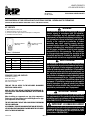
KIT CONTENTS
(1) OAS-LP# (Brass orifice) and
(1) ECO-LSS# (Brass low rate set screw),
(1) LP Conversion label (placed next to blank space on rating label,
(1) Installation Instruction Sheet
Main Burner Orifice
(OAS-LP#)
Low Rate Set Screw
(ECO-LSS-#)
Figure 1 - Kit Contents
Gas Conversion Kits, Natural Gas (NG) to Propane Gas (LP)
Cat. No. Model Ecoflow Electronic Model Fireplaces
F3502 LPK 1
BarcelonaLights36ZEN & VRE4636ZEN
F3503 LPK 2
BarcelonaLights48ZEN & VRE4648ZEN
F3504 LPK 3
BarcelonaLights60ZEN & VRE4660ZEN
F3505 LPK 4
BarcelonaLights72ZEN & VRE4672ZEN
Table 1

IHP.us.com 900861-06NC
2
CAUTION
The gas supply shall be shut OFF prior to discon-
necting the electrical power, before proceeding with
the conversion.
ATTENTION
Avant d’effecteur la conversion, coupez d’abord
l’alimentation en gaz, ensuite, coupez l’alimentation
electrique.
IMPORTANT
The burner orifice provided in this kit are only for use at
elevations of 0 to 2,000 feet (610 M) in the USA and 0 to
4,500 feet (0-1372 M) in Canada. At higher elevations
the BTU input must be de-rated by 4% for every 1,000
feet (305 M) to maintain the proper ratio of gas to air. If
the installer must convert the unit to adjust for varying
altitudes, a deration information sticker must be filled
out by the installer and adhered to the appliance at the
time of the conversion. Contact your local gas supplier
for deration requirements for your area.
GAS CONVERSION INSTRUCTIONS
IMPORTANT NOTE: When installing gas components use pipe joint com-
pound or Teflon tape on all pipe fittings before installing (ensure pro-
pane resistant compounds are used, do not use pipe joint compounds
on flare fittings).
Step 1. TURN OFF THE GAS SUPPLY TO THE FIREPLACE and disconnect
power supply at the circuit breaker. Ensure fireplace is cold.
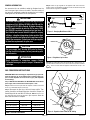
Step 2. Remove the burner pan from the fireplace to enable conversion
access. See installation manual if necessary.
Step 3. Disconnect the flex line at the main burner orifice. Then
remove the orifice and flared fitting from the orifice. Re-tape the
flared fitting with the new OAS-LP orifice per Table 2. Ensure to use
gas rated Teflon tape around the threads or pipe compound. Check for
leaks after conversion is complete.
Figure 2 - Changing Main Burner Orifice
Step 4. Locate the gas regulator on the opposite side of the valve box.
Using a regular size flat bladed screwdriver remove the aluminum cap and
washer from the regulator. See Figure 2.
Figure 3 - Regulator Cap Location
Model Main Burner Orifice Low Rate Set Screw
LPK1 (36” Fireplace) OAS-LP52 ECO-LSS-52
LPK2 (48” Fireplace) OAS-LP48 ECO-LSS-46
LPK3 (60” Fireplace) OAS-LP44 ECO-LSS-42
LPK4 (72” Fireplace) OAS-LP42 ECO-LSS-35
Table 2 - Reference Information
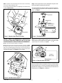
Figure 4 - Regulator Stem Shown in NG Setting
Step 5. On the underneath side of the aluminum cap is a plastic stem. Us-
ing a 6mm wrench remove the stem, unscrew the stem (counter-clockwise
), turn it over and install the opposite end back into the cap. See
Figure 4.
GENERAL INFORMATION
Gas conversion kits are available to adapt the fireplace from the
use of one type of gas to the use of another. These kits contain all
the necessary components needed to complete the task including
labeling that must be affixed to ensure safe operation.
Regulator
Valve Box
Pilot Box
Disconnect
Flex Line
Orifice
Regulator
Aluminum Cap
NG
Regulator
Plastic Stem

900861-06NC 3
IHP.us.com
NOTE: The plastic stem has a marking on it with an arrow. Look carefully
on the stem, it may be difficult to read.
The gas type is determined with the arrow pointing at the aluminum cap
as seen in Figures 4 and 5.
LP
Figure 5 - Regulator Stem Shown in LP Setting
CAUTION: ENSURE THE ALUMINUM CAP IS INSTALLED WITH
THE PLASTIC STEM SEATED COMPLETELY INTO THE CAP AND
THE METAL WASHER IS INSTALLED WITH THE ALUMINUM CAP.
Step 6. Secure the aluminum cap with a screwdriver.
Step 7. On the end of the burner pan where the pilot is located (see Figure
6), remove the four (4) 1/4” hex head screws securing the metal pilot box.
Two screws are located inside the burner pan, one on each side of the ig-
niter box screen mesh hood and the other two are securing a metal tab on
each side of the pilot box. See Figure 6 for screw locations.
Regulator
Plastic Stem
M
et
al P
il
o
t
B
o
x
B
urner Pan
Figure 6 - Pilot Box Screw Locations
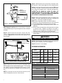
Step 8. Once the pilot box is loosen and exposes the pilot assem-
bly then proceed to removing the pilot hood.
The pilot hood will lift straight up and out of the pilot assembly af-
ter removing the wire clip with a small screwdriver or needle-nose
pliers. See Figure 7.
Figure 7 - Pilot Hood Removal
Step 9. Insert a small flat bladed screwdriver into the slot of the brass
orifice inside the pilot assembly and turn clockwise until it stops
(approximately 2 full revolutions). See Figure 8.
Figure 8 - Shows Slot Inside Pilot Orifice
Once the orifice has been converted to LP then re-install the pilot
hood, ensure the clip is in place (if removed) and mount the metal
pilot box back into place ins the same manner you removed it from
the burner pan. See Figure 6 as a reference.
Removable Clip
Vent Hole
(partially blocked
by brass orifice)
Pilot Hood
Top View of
Pilot Assembly
Slot

IHP.us.com 900861-06NC
4
REFERENCE INFORMATION
Figure 9 - Pilot Assembly Converted to LP
NOTE: Figures 51 and 52 provide a visual reference of the pilot
orifice from Natural gas to LP gas through the vent hole of the pilot
assembly.
Step 10. Look for the low rate set screw in the gas valve box.
There is a cutout (window) area that allows access to the low rate
set screw. Figure 10 shows the side view of the burner pan and a
close-up detail.
Figure 10 - Detailed Location of Low Rate Set Screw
Step 11. Remove the low rate set screw with a flat bladed screw-
driver turning the screw counter-clockwise . The set screw
has a rubber “O” ring on the outer portion of the screw, as a result
the screw will rotate only 3-4 revolutions and not unscrew any far-
ther.
NOTE: If you drop the low rate screw inside the valve area you can
retrieve it through the access door of the valve box.
Inlet Gas Pressure
Propane (LP)
Minimum Inlet 10.5” WC (2.61 kPa)
Maximum Inlet 13.0” WC (3.23 kPa)
Normal Inlet 11.0” WC (2.74 kPa)
Manifold Gas Pressure
Propane (LP)
Normal Manifold 10.0” WC (2.49 kPa)
Table 4 - Gas Pressures
Model: LP
Orifice
LP BTU’s
High
LP BTU’s
Low
LP Low Rate
Screw
BarcelonaLights36ZEN
and VRE4636ZEN #52 30,000
(8.79 kWh)
19,500
(5.72 kWh) #52
BarcelonaLights48ZEN
and VRE4648ZEN #48 42,500
(12.46 kWh)
29,000
(8.50 kWh) #46
BarcelonaLights60ZEN
and VRE4660ZEN #44 50,000
(14.65 kWh)
36,000
(10.55 kWh) #42
BarcelonaLights72ZEN
and VRE4672ZEN #42 60,000
(17.58 kWh)
45,000
(13.19 kWh) #35
Table 3 - Fireplace Input Specifications
Vent Hole
(mostly open after
converting to LP)
Pressure Tap Pressure Tap
Low Rate Set Screw
Valve Box
Burner Pan Side View
Low Rate
Set Screw
Step 12. Remove the low rate set screw using a small pair of nee-
dle-nose pliers. Grab the outer edge of the screw and pull outward.
Step 13. Insert the correct new low rate screw from Table 3 with
the needle-nose pliers. Secure the new low rate set screw (clock-
wise ) with screwdriver until it is tight and now longer spins.
CAUTION: DO NOT REMOVE OR LOOSEN THE SMALL SET
SCREWS ON EACH SIDE OF THE V-WIRE. THESE ARE PRES-
SURE TEST PORTS. IF THESE ARE LOOSENED THEY MUST BE
RE-TIGHTENED TO ENSURE NO GAS LEAKS OCCUR.
Step 14. Ensure you test the burner pan after it is installed into the
fireplace. Turn on gas supply and test for gas leaks, using a gas leak
test solution—also known as bubble leak solution.
NOTE: Using a soapy water solution is an effective leak test
solution but it is not recommended, because the soap residue that
is left on the pipes/fittings can result in corrosion over time.
A. Light the fireplace (refer to the lighting instructions label on the
appliance).
B. Brush all joints and connections with the gas leak test solution
to check for leaks. If bubbles are formed, or gas odor is
detected, turn off the appliance. Either tighten or refasten the
leaking connection, and then retest as described above.
C. When the gas lines are tested and leak free, rinse off the leak
testing solution.
WARNING
Never use an open flame to check for leaks.
Step 15. Fill out the label “This fireplace has been converted to LP
gas” and affix it to the blank area on the rating plate.
Step 16. Conversion is now complete.

900861-06NC 5
IHP.us.com
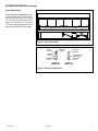
REFERENCE INFORMATION (continued)
Figure 11 - Proper Flame Height
Proper Flame Height
Proper flame height (Figure 11) should be
at the top edge of glass windshield (peak-
ing above at times) while on HI setting.
The LO setting will be at least half of the
height of HI or maybe lower. There can be
a variance in flame height between Natural
gas and Liquid Propane (LP) gas models.
Figure 12 - Burner Flame Appearance
No Blue Flame
Center
Soot at
Flame Tip
Dark Orange
Flame
IMPROPERLY
BURNING FLAME
Soot above
Flame Tip No Soot at
Flame Tip
PROPERLY
BURNING FLAME
Semi-Transparent
Yellow Flame
Blue Flame
Center

Printed in U.S.A. © 2015 Innovative Hearth Products
P/N 900861-06 Rev. NC 10/2017
IHP reserves the right to make changes at any time, without notice, in design, materials, specifica-
tions, prices and also to discontinue colors, styles and products. Consult your local distributor
for fireplace code information.
1508 Elm Hill Pike, Suite 108 • Nashville, TN 37210
6
-
 1
1
-
 2
2
-
 3
3
-
 4
4
-
 5
5
-
 6
6


Astria Fireplaces VRE 4600 Series Instruction Sheet
- Taper
- Instruction Sheet
- Ce manuel convient également à
dans d''autres langues
- English: Astria Fireplaces VRE 4600 Series
Documents connexes
-
Astria Fireplaces Gemini DLX Instruction Sheet
-
-
-
-
-
-
-
-
-