
NOTE: DIAGRAMS & ILLUSTRATIONS ARE NOT TO SCALE
P/N 750149M Rev. A 05/2015
HEARTH PRODUCTS
KITS AND ACCESSORIES
GAS CONVERSION KIT (GCK-LS)
1
P750083M
1
NOTE: DIAGRAMS & ILLUSTRATIONS NOT TO SCALE.
WARNING: THIS CONVERSION KIT SHALL BE INSTALLED
BY A QUALIFIED SERVICE AGENCY IN ACCORDANCE WITH
THE MANUFACTURER'S INSTRUCTIONS AND ALL APPLI-
CABLE CODES AND REQUIREMENTS OF THE AUTHORIZED
AGENCY HAVING JURISDICTION. IF THE INFORMATION IN
THESE INSTRUCTIONS ARE NOT FOLLOWED EXACTLY, A
FIRE, EXPLOSION OR PRODUCTION OF CARBON MONOX-
IDE MAY RESULT CAUSING PROPERTY DAMAGE, PER-
SONAL INJURY OR LOSS OF LIFE. THE INSTALLATION IS
NOT PROPER AND COMPLETE UNTIL THE OPERATION OF
THE CONVERTED APPLIANCE IS CHECKED AS SPECIFIED IN
THE OWNER INSTRUCTIONS SUPPLIED WITH THE KIT.
AVERTISSEMENT: CET ÉQUIPEMENT DE CONVERSION SERA INSTALLÉ
PAR UNE AGENCE QUALIFIÉE DE SERVICE CONFORMÉMENT AUX
INSTRUCTIONS DU FABRICANT ET TOUTES EXIGENCES ET CODES
APPLICABLES DE L'AUTORISÉS AVOIR LA JURIDICTION. SI
L'INFORMATION DANS CETTE INSTRUCTION N'EST PAS SUIVIE
EXACTEMENT, UN FEU, EXPLOSION OU PRODUCTION DE PROTOXYDE
DE CARBONE PEUT RÉSULTER LE DOMMAGES CAUSER DE
PROPRIÉTÉ, PERTE OU BLESSURE PERSONNELLE DE VIE. L'AGENCE
QUALIFIÉE DE SERVICE EST ESPONSABLE DE L'INSTALLATION
PROPRE DE CET ÉQUIPMENT. L'INSTALLATION N'EST PAS PROPRE
ET COMPLÉTE JUSQU'À L'OPÉRATION DE L'APPAREIL CONVERTI EST
CHÉQUE SUIVANT LES CRITÈRES ÉTABLIS DANS LES INSTRUCTIONS
DE PROPRIÉTAIRE PROVISIONNÉES AVEC L'ÉQUIPEMENT.
In Canada
THE CONVERSION SHALL BE CARRIED OUT
IN ACCORDANCE WITH THE REQUIREMENTS
OF THE PROVINCIAL AUTHORITIES HAVING
JURISDICTION AND IN ACCORDANCE WITH
THE REQUIREMENTS OF THE CAN1-B149.1
AND .2 INSTALLATION CODE.
LA CONVERSION DEVRA ÊTRE EFFECTUÉE
CONFORMÉMENT AUX RECOMMANDATIONS
DES AUTORITÉS PROVINCIALES AYANT
JURIDICTION ET CONFORMÉMENT AUX
EXIGENCES DU CODE D'INSTALLATION CAN1-
B149.1 ET.2.
This Gas Conversion Kit contains all of the
necessary components needed to complete the
conversion of an appliance from the use of one
type of gas to the use of another, including
labeling that must be affixed to ensure safe
operation.
ALWAYS REFER TO THE APPLIANCE IN-
STALLATION AND HOMEOWNERS CARE
AND OPERATION DOCUMENTS BEFORE
COMPLETING A CONVERSION. ALL
WARNINGS, CAUTIONS AND DETAILED
INSTRUCTIONS CONTAINED THEREIN
ARE APPLICABLE TO THIS DOCUMENT.
To complete the conversion proceed as follows:
Note: After converting the valve and gas compo-
nents, refer to the appliance installation and
homeowners care and operation instructions to
adjust the air shutter opening for the gas type used.
Step 1. Turn off the gas supply to the
appliance. Remove the front frame and
glass door from the appliance. Access the
control compartment.
Step 2. Carefully remove the logs. Exercise
care as not to break the logs.
Step 3. Remove the grate.
HEARTH PRODUCTS
KITS AND ACCESSORIES
GAS CONVERSION KIT
(GCK-LS)
750,149M REV. N/C
8/2002
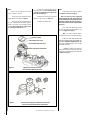
Figure 1
See Figure 1 for step 4 part removal details:
Step 4
a. Remove the front baffle by remov-
ing the two securing screws.
b. Remove the two screws securing
the end tabs of the front burner. Remove the
front burner.
c. Remove the two screws securing
each of the rear burner clamps. Remove the
rear burner.
Burner Assembly

2
2
NOTE: DIAGRAMS & ILLUSTRATIONS NOT TO SCALE.
a.
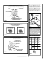
Convert the pilot orifice as follows
(see Figures 4, 5 and 6 on page 3):
Note - Use extra care not to engage the
orifice strip with the 7/16" open end wrench
(contacting the orifice strip could cause strip
distortion rendering the pilot inoperative).
Also avoid wrench contact to any of the other
pilot parts.
Use a 7/16" open end wrench and turn
the pilot hex fitting counter-clockwise 1/4
turn. (See
Figure 4 on page 3).
Note - The orifice strip tab may be
randomly located on any side of the hex fitting.
b. Push the orifice strip tab all the way
against the hex fitting to align the appropriate gas
type orifice
(see Figures 5 and 6 on page 3)
. The
type of gas for which the pilot is set, is, the gas
type shown on the tab.
c. Retighten, clockwise, the pilot hex
fitting until the pilot hood aligns with the
thermopiles as indicated by the arrows shown
in
Figure 4 on page 3
.
Step 5.
Convert the Honeywell RF Comfort
Control Valve as follows:
a. Access the gas selector by remov-
ing the motor cover.
Refer to
Figure 2.
b. Using a slot-type screwdriver, push
the gas selector down and rotate until the
arrows on it point to the correctly colored
screw: red for LP/propane gas usage or blue
for natural gas. Refer to
Figure 2.
MOTOR COVER
GAS SELECTOR SCREW
RED SCREW (LP/propane)
BLUE SCREW (NATURAL GAS)
Figure 2
OR
PINS
Figure 3
Adjusting the Fuel Selector on the
Honeywell RF Comfort Control Valve
Insertion of the LP/propane or Natural Gas Conversion
Plug on the Honeywell RF Comfort Control Valve
c. Insert the conversion plug for the
fuel being used as shown in
Figure 3
. Use the
red plug for LP/propane gas usage or the
blue one for natural gas.
d. Attach the correct gas conversion
label to the gas valve (see
Figure 2)
.
e. Replace the motor cover.
Step 6

3
3
NOTE: DIAGRAMS & ILLUSTRATIONS NOT TO SCALE.
Figure 8
Step 7. Unscrew the rear and front main
burner orifices
(Figure 7)
from their respec-
tive manifolds and replace them with the
ones provided in this kit. There are two main
burner orifices provided in this gas conver-
sion kit. Refer to
Table 1
for the correct
front and rear main burner orifice sizes for
the gas being used. The orifice size is
stamped on the orifice. See
Figure 8.
Pilot for the Honeywell RF Comfort Control Valve
(Loosening of Hex Fitting For Orifice Strip Tab Positioning)
Pilot for the Honeywell RF Comfort Control Valve
Pilot for the Honeywell RF Comfort Control Valve
Orifice Strip Tab Positioning
Figure 5
Figure 6
Figure 4
Figure 7
WARNING: INCORRECT ORIFICE SIZE
INSTALLATION ON EITHER BURNER
MAY RESULT IN POOR COMBUSTION
WHICH MAY LEAD TO THE PRODUC-
TION OF CARBON MONOXIDE. IT MAY
ALSO CAUSE SOOTING WITHIN THE
FIREPLACE/VENTING SYSTEM.
seziSecifirOrenruBniaM-1elbaT
tinU
eziS
saG
epyT
tnorF
renruB
raeR
renruB
53-SSL
larutaN
saG 05
#4
4#
/PL
enaporP 16
#5
5#
04-SSL
larutaN
saG 54
#2
4#
/PL
enaporP 65
#h
cni450.0

P750083M
Printed in U.S.A. © 2015 INNOVATIVE HEARTH PRODUCTS LLC
P/N 750149M Rev. A 05/2015
1508 Elm Hill Pike, Suite 108
Nashville, TN 37210
IHP.US.COM
Innovative Hearth Products reserves the right to make changes at any time,
without notice, in design, materials, specifications, and prices, and also to
discontinue colors, styles, and products.
Consult your local distributor for fireplace code information.
4
P750149M
4NOTE: DIAGRAMS & ILLUSTRATIONS NOT TO SCALE.
Printed in U.S.A. © 2002 by LENNOX
P/N 750,149M REV. N/C 8/2002
The manufacturer reserves the right to make changes at any time, without notice, in
design, materials, specifications, prices and also to discontinue colors, styles and
products. Consult your local distributor for fireplace code information.
1110 West Taft Avenue • Orange, CA 92865
Step 10. Turn on gas supply and test for gas
leaks, using a soapy water solution.
Step 11.
Attach a manometer to the manifold
side pressure test fitting and verify manifold
pressure reads 3.5 inches water column (0.87
kPa) for natural gas, and 10.0 inches water
column (2.49 kPa) for propane gas.
Step 8. Reassemble all removed components
by reversing the procedures outlined in the
preceding steps. Use pipe joint compound or
Teflon tape on all pipe fittings before installing
(ensure propane resistant compounds are used
in propane applications, do not use pipe joint
compounds on flare fittings). Adjust the air
shutter opening on the burner tube, referring
to the Note on
page 1.
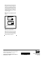
Step 9. Attach the conversion kit label
(Figure 9 )
to the rating plate on the
appliance.
Figure 9
Example Labels
(Each Kit Contains Only One Label)
INPUT BTU/HR 50,000
MANIFOLD PRESSURE 3.5"
ORIFICE SIZE (0.130)
INPUT BTU/HR 50,000
MANIFOLD PRESSURE 10"
ORIFICE SIZE (0.080)
NOTE: DIAGRAMS & ILLUSTRATIONS NOT TO SCALE.
-
 1
1
-
 2
2
-
 3
3
-
 4
4


Astria Fireplaces LSS3540 Instruction Sheet
- Taper
- Instruction Sheet
- Ce manuel convient également à
dans d''autres langues
- English: Astria Fireplaces LSS3540
Documents connexes
Autres documents
-
Superior Fireplaces DRT3500 Multi-View Mode d'emploi
-
-
Lennox merit plus mpb3530cpm-b Manuel utilisateur
-
-
-
Superior SDV35 Manuel utilisateur
-
-
Miller Fireplaces - Direct Vent Gas Mode d'emploi
-