Garland 36ER33-88 Owner Instruction Manual
- Catégorie
- Fours
- Taper
- Owner Instruction Manual

Part Number: 4520414 Rev 2 9/14
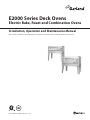
E2000 Series Deck Ovens
Electric Bake, Roast and Combination Ovens
Installation, Operation and Maintenance Manual
This manual is updated as new information and models are released. Visit our website for the latest manual.

Part Number: 4520414 Rev 2 9/14Page 2
SAFETY NOTICES
WARNING:
This product contains chemicals known to the state of california to cause cancer and/or birth defects
or other reproductive harm. Installation and servicing of this product could expose you to airborne
particles of glass wool/ceramic fibers. Inhalation of airborne particles of glass wool/ceramic fibers
is known to the state of California to cause cancer.
Keep appliance area free and clear of combustibles.
Disconnect from electrical supply before servicing.
Rights written notice
2012 ALL RIGHTS RESERVED. This manual and the text and images it contains
may not be modi ed in any way, by any means, without written permission from
Garland Commercial Ranges Ltd.
Users are cautioned that maintenance and repairs must be performed by a Garland authorized service agent
using genuine Garland replacement parts. Garland will have no obligation with respect to any product that has been
improperly installed, adjusted, operated or not maintained in accordance with national and local codes or installation
instructions provided with the product, or any product that has its serial number defaced, obliterated or removed,
or which has been modified or repaired using unauthorized parts or by unauthorized service agents.
For a list of authorized service agents, please refer to the Garland web site at http://www.garland-group.com.
The information contained herein, (including design and parts specifications), may be superseded and is subject
to change without notice.
FOR YOUR SAFETY:
DO NOT STORE OR USE GASOLINE
OR OTHER FLAMMABLE VAPORS OR
LIQUIDS IN THE VICINITY OF
THIS OR ANY OTHER
APPLIANCE
WARNING:
IMPROPER INSTALLATION, ADJUSTMENT,
ALTERATION, SERVICE OR MAINTENANCE
CAN CAUSE PROPERTY DAMAGE, INJURY,
OR DEATH. READ THE INSTALLATION,
OPERATING AND MAINTENANCE
INSTRUCTIONS THOROUGHLY
BEFORE INSTALLING OR
SERVICING THIS EQUIPMENT
PLEASE READ ALL SECTIONS OF THIS MANUAL
AND RETAIN FOR FUTURE REFERENCE.
THIS PRODUCT HAS BEEN CERTIFIED AS
COMMERCIAL COOKING EQUIPMENT AND
MUST BE INSTALLED BY PROFESSIONAL
PERSONNEL AS SPECIFIED.
INSTALLATION AND ELECTRICAL CONNECTION
MUST COMPLY WITH CURRENT CODES:
IN CANADA - THE CANADIAN ELECTRICAL
CODE PART 1 AND / OR LOCAL CODES.
IN USA – THE NATIONAL ELECTRICAL CODE
ANSI / NFPA – CURRENT EDITION.
ENSURE ELECTRICAL SUPPLY CONFORMS WITH
ELECTRICAL CHARACTERISTICS SHOWN ON
THE RATING PLATE.

Part Number: 4520414 Rev 2 9/14 Page 3
TABLE OF CONTENTS
SAFETY NOTICES. . . . . . . . . . . . . . . . . . . . . . . . . . . . . . . . . . . . . . . . . . . . . . . . . . . . 2
INTRODUCTION. . . . . . . . . . . . . . . . . . . . . . . . . . . . . . . . . . . . . . . . . . . . . . . . . . . . . 4
Uncrating . . . . . . . . . . . . . . . . . . . . . . . . . . . . . . . . . . . . . . . . . . . . . . . . . . . . . . . . . . . . . . . . . . . . . . . .4
Rating Plate . . . . . . . . . . . . . . . . . . . . . . . . . . . . . . . . . . . . . . . . . . . . . . . . . . . . . . . . . . . . . . . . . . . . . .4
SPECIFICATIONS . . . . . . . . . . . . . . . . . . . . . . . . . . . . . . . . . . . . . . . . . . . . . . . . . . . . 5
INSTALLATION . . . . . . . . . . . . . . . . . . . . . . . . . . . . . . . . . . . . . . . . . . . . . . . . . . . . . . 6
Location of the Oven . . . . . . . . . . . . . . . . . . . . . . . . . . . . . . . . . . . . . . . . . . . . . . . . . . . . . . . . . . . . .6
Clearances . . . . . . . . . . . . . . . . . . . . . . . . . . . . . . . . . . . . . . . . . . . . . . . . . . . . . . . . . . . . . . . . . . . . . . .6
Assembly Instructions . . . . . . . . . . . . . . . . . . . . . . . . . . . . . . . . . . . . . . . . . . . . . . . . . . . . . . . . . . . .6
Electrical Connections . . . . . . . . . . . . . . . . . . . . . . . . . . . . . . . . . . . . . . . . . . . . . . . . . . . . . . . . . . . .6
Break-In Procedure . . . . . . . . . . . . . . . . . . . . . . . . . . . . . . . . . . . . . . . . . . . . . . . . . . . . . . . . . . . . . . .6
OPERATION AND MAINTENANCE. . . . . . . . . . . . . . . . . . . . . . . . . . . . . . . . . . . . . 7
Stainless Steel Finishes . . . . . . . . . . . . . . . . . . . . . . . . . . . . . . . . . . . . . . . . . . . . . . . . . . . . . . . . . . .7
Oven Interior . . . . . . . . . . . . . . . . . . . . . . . . . . . . . . . . . . . . . . . . . . . . . . . . . . . . . . . . . . . . . . . . . . . .7
Cleaning of Core Plates . . . . . . . . . . . . . . . . . . . . . . . . . . . . . . . . . . . . . . . . . . . . . . . . . . . . . . . . . . .7

Part Number: 4520414 Rev 2 9/14Page 4
INTRODUCTION
Your new equipment should be given regular care and
maintenance. Periodic inspections by your dealer or a
quali ed service agency are recommended.
This product has been certi ed as commercial cooking
equipment and must be installed by professional personnel
as speci ed.
Uncrating
Carefully remove unit from crate or carton. All packing
material should be removed from units. On stainless steel
units the protective material covering the stainless steel
should be removed.
After uncrating, immediately check the equipment for visible
signs of shipping damage.
If such damage has occurred, do not refuse shipment, but
contact the shipper and le the appropriate freight claims.
Rating Plate
When corresponding with the factory or your local
authorized factory service center regarding service problems
or replacement parts, be sure to refer to the particular unit
by the correct model number (including the pre x and su x
letters and numbers) and the warranty serial number. The
serial plate is attached to the inside of the control panel of
the lower oven section contains this information.
Before attempting the electrical connection, the rating
pate should be checked to ensure that the unit’s electrical
characteristics and the supply characteristics agree.

Part Number: 4520414 Rev 2 9/14 Page 5
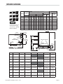
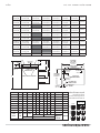
SPECIFICATIONS
Model
Total KW
Loading
Nominal Amperes Per Phase Shipping
3 Phase Single Phase
Cu.Ft.
Weight
lbs/kg
240V 208 V
240V 208V
240 & 208 X Y Z X Y Z
E2001 6.2kW 11 15 23 12.5 17.3 26 26 30 73 550/249
E2011 12.4 kW 32 26 32 37 30 37 52 60 146 970/440
E2111 18.6kW 45 45 45 51.5 51.5 51.5 77.5 90 219 1410/640
E2005 6.2kW 11 15 23 12.5 17.3 26 26 30 73 660/299
E2055 12.4kW 32 26 32 37 30 37 52 60 146 1260/572
E2555 18.6kW 45 45 45 51.5 51.5 51.5 77.5 90 219 1890/857
E2015 12.4 kW 32 26 32 37 30 37 53 60 146 1120/506
E2115 18.6kW 45 45 45 51.5 51.5 51.5 77.5 90 219 1550/703
E2155 18.6 kW 45 45 45 51.5 51.5 51.5 77.5 90 219 1670/750
Model A B C D E Width Depth
E2001 51" (1295mm) 27" (686mm) 36.5" (927mm)
55.5"
(1410mm)
36"
(914mm)
E2011 66" (1676mm) 23" (584mm) 32.5" (826mm)
51.5"
(1308mm)
55.5"
(1410mm)
36"
(914mm)
E2111 66" (1676mm) 4" (102mm) 13.5" (343mm) 32.5" (826mm)
51.5"
(1308mm)
55.5"
(1410mm)
36"
(914mm)
E2005 51" (1295mm) 23" (584mm) 32.5" (826mm)
55.5"
(1410mm)
36"
(914mm)
E2055 67" (1701mm) 16" (406mm) 25.5"(648mm)
48.5"
(1232mm)
55.5"
(1410mm)
36"
(914mm)
E2555 78" (1980mm) 4" (102mm) 13.5" (343mm) 36.5" (927mm)
59.5"
(1511mm)
55.5"
(1410mm)
36"
(914mm)
E2015 63" (1600mm) 16" (406mm) 25.5" (648mm)
48.5"
(1232mm)
55.5"
(1410mm)
36"
(914mm)
E2115 70" (1777mm) 4" (102mm) 13.5" (343mm) 36.5" (927mm)
55.5"
(1410mm)
55.5"
(1410mm)
36"
(914mm)
E2155 74" (1782mm) 4" (1028mm) 13.5" (343mm) 36.5" (927mm)
59.5"
(1511mm)
55.5"
(1410mm)
36"
(914mm)
36"
[915mm]
ALL MODELS
3-5/16"
[84mm]
CABLE
ENTRANCE
FLUE VENT
4-11/16"
[119mm]
CABLE
CONNECTION
8-7/8"
[225mm]
5-1/8"
[130mm]
CABLE
ENTRANCE
2-1/4"
[57mm]
55-1/2"
[1410mm]
ALL MODELS
CABLE ENTRANCES
CABLE
CONNECTION
6-1/2"
[165mm]
2-3/4"
[70mm]
A
B
5" BASE
[127mm]
C
D
E
E2015
E2111
8B
8B
8B
12R
8B
E2001
8B
12R
12R
E2055
E2011
8B
8B
12R
12R
8B
12R
12R
12R
E2555
E2155
E2115
E2005
12R
8B
8B
12R
8B = 8" Bake
12R = 12" Roast
Standard wiring 240 V or
208 V (197/219) Single
or Three Phase – Specify
which is required

Part Number: 4520414 Rev 2 9/14Page 6
4. When two pizza ovens (2001P) are stacked, remove the
top louvers on the bottom oven. Assemble as illustrated
in instructions found with the stacking plates.
DO NOT under any circumstances; connect the vent stack
of the oven directly to the ue pipe or a vent system. If this
is done, it seriously decreases the e ciency and will cause
uneven heating of the section. If an outside ue connection
must be made, a suitable hood placed 12” (305mm) above
the oven ue must be provided to prevent direct suction of
the air through the oven sections.
Electrical Connections
The installation and connection should comply with current
codes. In Canada - The Canadian Electrical Code Part 1 and/or
local codes. In the U.S.A. - The National Electrical Code ASNA/
NFPA - current edition.
Before attempting the electrical connection, the rating
plate should be checked to ensure that the unit’s electrical
characteristics and the supply characteristics agree.
The unit has been wired as speci ed on the factory order
and the rating plate is stamped with the information. If it is
necessary to change the phase, refer to the wiring diagram
attached to the main terminal block, or refer to the rating
plate.
Electrical connection may be made though the knockout at
the rear of bottom of the unit to the terminal block located
directly behind the switch panel on the main bottom. Hinge
switch panel open.
For the supply connection use suitable wire for 60° C.
Break-In Procedure
It is strongly recommended that the 2000 Series ovens
supplied with core plates be put through a break-in period
to eliminate possible warpage of the core plates caused by
moisture absorption.
This action need only be carried out once providing the
ovens are used daily, however, if the ovens are left idle for an
extended period of time allowing the core plates to absorb
moisture, the following procedure must be again carried out.
Turn the top and bottom heat selector switched to HI, set the
thermostat to 300°F (149°C) maximum and allow the oven to
operate (without any product in the oven), for approximately
8 hours.
Location of the Oven
Appliances shall be installed in a location in which the
facilities for ventilation permit proper venting and where
there is su cient space for servicing. Appliances shall be
located so as not to interfere with proper circulation of
air within the con ned space. When buildings are so tight
that normal in ltration does not provide the necessary air,
outside air shall be introduced.
Clearances
The 2000 E series ovens must be installed with a minimum
of zero (0”) clearance to the sides and back to walls of
combustible material.
Assembly Instructions
1. Open the bottom section of the crate and the leg crate.
Proceed with oven assembly as follows:
a. Fasten lefts to base using 1/4” hex head bolts, locking
washers and nuts provided.
b. Ensure the insulation is evenly spread and in the
proper position on the top of the lower unit.
c. Place an 1” x 4” x 60” (22mm x 100mm x 1525mm)
long piece of lumber across the rear top of the oven
to prevent the stacks from misaligning.
d. Raise the center of top oven section up and on to the
lower oven section, sliding the oven section forward
until the main sides of the section engage behind the
oven front.
e. Remove the piece of lumber and lower the rear of the
oven section into position.
f. Secure the left and right out side front corners of
the oven section using No. 1-24 x 1/2” at head bolts
supplied.
g. Secure the oven backs using six 10-1/2” truss head
sheet metal screws.
2. To connect the section feed wires to the main oven
terminal block, refer to the wiring diagram attached to
the main terminal block.
3. With the oven(s) in the desired position, use a sprint level
and level unit four ways: across front and back, and down
left and right edges.
INSTALLATION

Part Number: 4520414 Rev 2 9/14 Page 7
OPERATION AND MAINTENANCE
Top and bottom heating units are each operated by a three
heat heavy duty reversible switch. An oven thermostat with
pilot light is also provided. The thermostat maintains the
temperature and the switches determine the source of the
heat.
1 Turn the top heating unit to HIGH.
2 Turn the bottom heating unit to HIGH.
3. Set the oven thermostat to the desired temperature. The
pilot light will now come ON.
4. When the desired temperature is reached, the pilot light
will go OFF. At this time the top heating unit switch may
be turned OFF or set as desired.
5 The bottom heating unit switch may be left at HIGH or
adjusted as desired.
5. Hold the dial shaft steady and with a screwdriver, turn the
calibration screw, located inside the dial shaft clockwise
to decrease and counter-clock wise to increase the
temperature. I.E. 1/4 turn = 35°F (19.5°C).
6. Replace the thermostat dial and repeat steps 1 through 3
to verify that the correct adjustment has been made.
Stainless Steel Finishes
For routine cleaning, just wash with a hot water and
detergent solution. Wash just a small area at a time or the
water will evaporate leaving the chemicals behind causing
streaking.
Rinse the washed area with a clean sponge dipped in a
sanitizing solution. Wash just a small area at a time or the
water will evaporate leaving the chemicals behind causing
streaking.
Rinse the washed area with a clean sponge dipped in a
sanitizing solution and wipe dry with a soft clean cloth
before it can dry.
Use a paste (of water and a mild scouring powder) if you
have to, but never rub against the grain. All stainless steel has
been polished in one direction. Rub with the polish lines to
preserve the original nish. Then thoroughly rinse as before.
To prevent ngerprints, there are several stainless steel
polishes on the market that leave an oily or waxy lm. Do not
use on surfaces that will be in contact with food.
Stainless Steel may discolour if overheated. These stains can
usually be removed by vigorous rubbing with a scouring
powder paste.
Use only stainless steel, wood or plastic tools, if necessary,
to scrape o heavy deposits of grease and oil. Do not use
ordinary steel scrapers or knives as particles of the iron may
become imbedded and rust. STEEL WOOL SHOULD NEVER BE
USED.
Oven Interior
Standard aluminized steel interior surfaces. The oven linings,
back linings and top linings are formed with heavy gauge
steel with aluminum fused into its surface. This provides
a re ectance of heat back to the food being prepared.
The aluminum virtually eliminates the possibility of rust
formation.
To clean the aluminized interior, use a concentrated
detergent on a plastic pad to remove burned on soil. DO NOT
use steel wool, oven cleaners or abrasive powders. These will
remove the aluminum. Rinse with warm water on soft cloth.
Be sure to remove all traces of detergent. Any discoloration
which may remain after the soil build-up has been removed
will not a ect the performance of the oven.
Cleaning of Core Plates
1. Set the thermostat dial to 550°F (288°C) at the end of the
cooking day and allow to cycle for one hour.
2. When the oven has cooled the residue will have
carbonized and can be removed by sweeping with a sti
wire brush.
3. Stubborn residue can be loosened with a scraper.

GARLAND
1177 KAMATO ROAD, MISSISSAUGA, ONTARIO, CANADA. L4W1X4
8447242273
WWW.GARLANDGROUP.COM
To learn how Manitowoc Foodservice and its leading brands can equip you, visit our global web site at
www.manitowocfoodservice.com, then discover the regional or local resources available to you.
©2014 Manitowoc Foodservice except where explicitly stated otherwise. All rights reserved. Continuing product improvement may necessitate change of speci cations without notice.
Part Number 4520414 Rev 2 9/14
Every new piece of Manitowoc Foodservice equipment comes with KitchenCare™ and you choose the level of service that meets
your operational needs from one restaurant to multiple locations.
StarCare – Warranty & lifetime service, certi ed OEM parts, global parts inventory, performance audited
ExtraCare — CareCode, 24/7 Support, online/mobile product information
LifeCare – Install & equipment orientation, planned maintenance, KitchenConnect™, MenuConnect
Talk with KitchenCare™ • 1-844-724-CARE • www.mtwkitchencare.com

GARLAND
1177 KAMATO ROAD, MISSISSAUGA, ONTARIO, CANADA.P L4W1X4
8447242273
WWW.GARLANDGROUP.COM
To learn how Manitowoc Foodservice and its leading brands can equip you, visit our global web site at
www.manitowocfoodservice.com, then discover the regional or local resources available to you.
©2014 Manitowoc Foodservice except where explicitly stated otherwise. All rights reserved. Continuing product improvement may necessitate change of speci cations without notice.
Numéro de pièce 4520414 rév 2 9/14
Every new piece of Manitowoc Foodservice equipment comes with KitchenCare™ and you choose the level of service that meets
your operational needs from one restaurant to multiple locations.
StarCare – Warranty & lifetime service, certi ed OEM parts, global parts inventory, performance audited
ExtraCare — CareCode, 24/7 Support, online/mobile product information
LifeCare – Install & equipment orientation, planned maintenance, KitchenConnect™, MenuConnect
Talk with KitchenCare™ • 1-844-724-CARE • www.mtwkitchencare.com

Numéro de pièce 4520414 rév 2 9/14 Page 7
FONCTIONNEMENT ET ENTRETIEN
Les unités de chau age inférieure et supérieure fonctionnent
à l'aide de commutateur réversible à haut rendement. Le
thermostat ainsi que la lumière du pilote sont fournis. Le
thermostat maintient la température et les commutateurs
déterminent la source de chaleur.
1 Tournez l'unité de chau age supérieure à la position
ÉLEVÉE.
2 Tournez l'unité de chau age inférieure à la position
ÉLEVÉE.
3. Réglez le thermostat du four à la température désirée. Le
pilote S'ALLUMERA.
4. Lorsque la température désirée est atteinte, la lumière du
pilote S'ÉTEINDRA. À ce point, le commutateur de l'unité
de chau age supérieur peut être FERMÉ ou réglé au
besoin.
5 Le commutateur de l'unité de chau age inférieur peut
être laissé à la position ÉLEVÉE ou réglé au besoin.
5. Maintenez l'arbre du cadran fermement et, à l'aide
d'un tournevis, tournez la vis de calibration, située à
l'intérieur de l'arbre du cadran, dans le sens horaire pour
diminuer la température ou dans le sens antihoraire
pour augmenter la température. C.-À.-D. 1/4 tour = 35°F
(19.5°C).
6. Replacez le cadran du thermostat et répétez les étapes 1
à 3 pour véri er que l'ajustement adéquat fut e ectué.
Finis en acier inoxydable
Pour un entretien régulier, nettoyez à l'aide d'eau chaude et
d'un détergent. Nettoyez une petite section à la fois sinon
l'eau s'évaporera laissant des traces de résidus chimiques qui
engendreront des stries.
Rincez et nettoyez la section à l'aide d'une éponge propre
trempée dans une solution désinfectante. Nettoyez une
petite section à la fois sinon l'eau s'évaporera laissant des
traces de résidus chimiques qui engendreront des stries.
Rincez et nettoyez la section à l'aide d'une éponge propre
trempée dans une solution désinfectante et essuyez avec un
chi on propre et sec avant que la solution ne soit sèche.
Utilisez une pâte (solution d'eau et de poudre récurrente
douce) au besoin mais, ne jamais frotter dans le sens
contraire du grain du métal. L'acier inoxydable a été poli dans
une seule direction. Frotter à l'aide d'un produit de nition
pour préserver le ni original. Puis, rincez comme indiqué
ci-dessous.
Pour prévenir les marques de doigts, il existe plusieurs
produits de nition pour acier inoxydable laissant une
pellicule huileuse ou cireuse. Ne pas utiliser sur les surfaces
qui seront en contact avec la nourriture.
L'acier inoxydable peut se décolorer si celui-ci est surchau é.
Habituellement, ces taches peuvent être enlevées par un
frottage vigoureux avec une pâte de poudre récurrente.
Utilisez des outils en acier inoxydable, en bois ou en
plastique seulement, au besoin, pour enlever les dépôts de
gras ou d'huile de grandes tailles. Ne pas utiliser un grattoir
en métal ordinaire ou un couteau puisque des particules de
fer peuvent se détacher et rouiller. NE JAMAIS UTILISER UNE
LAINE D'ACIER.
Intérieur du four
Surfaces internes en acier aluminié standard. Les
revêtements de four, revêtements arrière et revêtements
supérieurs sont faits d'acier épais avec aluminium fusionné
à la surface. Ceci permet une ré exion de la chaleur
aux aliments en cours de cuisson. L'aluminium élimine
pratiquement toute possibilité de formation de rouille.
Pour nettoyer l'intérieur aluminié, utilisez une éponge
trempée dans un détergent concentré pour enlever les
brûlures sur la surface. NE PAS utiliser de laine d'acier, de
nettoyants pour fours ou de poudres abrasives. Ceux-ci
enlèveront l'aluminium. Rincez avec de l'eau chaude sur
un chi on doux Assurez-vous d'enlever toutes traces de
détergent. Toute décoloration résiduelle, après avoir enlevé
les dépôts du la surface, n'a ecteront pas les performances
du four.
Nettoyer les plaques internes
1. Réglez le cadran du thermostat à 550°F (288°C) à la n de
la journée d'utilisation et faire un cycle de une heure.
2. Lorsque le four est refroidi, les résidus seront carbonisés
et pourront être enlevés à l'aide d'une brosse métallique
rigide.
3. Les résidus tenaces peuvent être détachés à l'aide d'un
grattoir.

Numéro de pièce 4520414 rév 2 9/14Page 6
Emplacement du four
Les appareils doivent être installés dans un endroit dans
lequel les installations de ventilation permettent une
ventilation adéquate et où il y a su samment d’espace
pour l’entretien. Les appareils doivent être installés dans
un endroit de façon à ne pas interférer avec une circulation
d’air adéquate dans l’espace con né. Lorsque les bâtiments
sont près les uns des autres, de façon à ce qu’une in ltration
normale ne fournit pas l’entrée d’air nécessaire, de l’air en
provenance de l’extérieur doit être introduit.
Zones de dégagement
Les fours de la série 2000E doivent être installé avec une
zone de dégagement minimale de (0pouce) sur les côtés et à
l'arrière aux matières combustibles
Directives d'assemblage
1. Ouvrez la section inférieure et les pattes de l'emballage.
Procédez à l'assemblage du four comme ceci:
a. Vissez les pattes à la base du four à l'aide des boulons
à tête hexagonale 1/4 pouce, rondelles d'arrêt ainsi
que les écrous sont fournis.
b. Assurez-vous que l'isolant est dans la bonne position
et qu'il est bien réparti sur la partie supérieure de
l'unité inférieure.
c. Placez une pièce de bois d'une longueur de 1pouce
x 4pouces x 60pouces (22mm x 100mm x 1525mm
ou 2,54cm x 10.16cm x 152.40cm) sur la partie
supérieure arrière du four pour empêcher un
désalignement des unités superposées.
d. Soulevez et alignez la partie centrale du four
supérieur sur le four inférieur, en faisant glisser la
section vers l'avant jusqu'à ce que les côtés du four
supérieur s'engagent sur la partie arrière devant le
four.
e. Enlevez la pièce de bois et faites descendre la partie
arrière du four en position.
f. Sécurisez les coins gauche et droit situés à l'avant du
four en utilisant les boulons à tête plate numéro 1-24
x 1/2pouce fournis.
g. Sécurisez l'arrière du four en utilisant six vis à tête
bombées à tôle de 10-1/2pouce.
2. Pour brancher les ls d'alimentation au bloc de jonction
principal, veuillez vous référer au schéma électrique situé
sur le bloc de jonction principal.
3. Lorsque les fours sont à la position désirés, utilisez un
niveau pour aligner l'appareil selon les quatre façons
suivantes: avant et arrière ainsi que les côtés droit et
gauche.
4. Lorsque deux fours à pizza (2001P) sont superposés,
enlevez la grille d'aération du four inférieur. Procédez
à l'assemblage comme illustré sur les instructions
retrouvées sur les plaques d'empilage.
NE PAS, en aucune circonstance, connectez le conduit
de ventilation du four directement sur le conduit de
raccordement ou au système de ventilation. Si cette
méthode est employée, ceci réduit grandement l'e cacité
et entraînera une chaleur inégale. Si un raccordement
extérieur doit être fait, une hotte appropriée placée à
12pouces (305mm ou 30,48cm) au-dessus du conduit
de raccordement du four doit être installée pour prévenir
l'aspiration directe de l'air à travers les sections de fours.
Raccordements électriques
L'installation ainsi que les connexions doivent être conformes
aux codes actuels. Au Canada - Le code canadien de
l'électricité partie1/et ou les normes locales. Aux États-Unis -
The National Electrical Code ASNA/NFPA - présente édition.
Avant de procéder au raccordement électrique, une
véri cation de la plaque signalétique devrait être faite
pour s'assurer que les caractéristiques électriques et
d'alimentations électriques de l'appareil sont conformes.
L'appareil fut câblé comme sur l'ordre de fabrication et la
plaque signalétique, estampillée, présente l'information.
S'il est nécessaire de procéder à un changement de phase,
référez-vous au schéma électrique, situé sur le bloc de
jonction principal ou référez-vous à la plaque signalétique.
Les connexions électriques peuvent être e ectuées à travers
une alvéole défonçable à l'arrière, de l'appareil inférieur, au
bloc de jonction situé directement à l'arrière du panneau de
contrôle de l'appareil inférieur. Panneau de commutateur à
charnière ouverte.
Pour ce type de connexion, utilisez un câble approprié pour
60° C.
Procédure de rodage
Il est très recommandé que les fours de la série 2000, avec
plaques internes soient soumis à une période de rodage
pour éliminer toute déformation possible, des plaques
internes, causée par l'absorption d'humidité.
Cette procédure doit être e ectuée une seule fois pour
les fours utilisés chaque jour cependant, si les fours sont
inactifs pour une période prolongée, ce qui engendre une
absorption d'humidité par les plaques internes, la procédure
ci-dessus doit être e ectuée à nouveau.
Tournez le commutateur supérieur et inférieur à la position
ÉLEVÉE, réglez le cadran du thermostat à une température
maximale de 300°F (149°C) pour permettre au four de
fonctionner (sans produit à l'intérieur) pour une période
d'environ 8heures.
INSTALLATION

Numéro de pièce 4520414 rév 2 9/14 Page 5
CARACTÉRISTIQUES
Modèle
Charge
total KW
Intensité nominale par phase Livraison
3phases Phase simple
Pied
cube
Poids
lb/kg
240V 208V
240V 208V
240 & 208 X Y Z X Y Z
E2001 6,2kW 11 15 23 12.5 17.3 26 26 30 73 550/249
E2011 12,4kW 32 26 32 37 30 37 52 60 146 970/440
E2111 18,6kW 45 45 45 51.5 51.5 51.5 77.5 90 219 1410/640
E2005 6,2kW 11 15 23 12.5 17.3 26 26 30 73 660/299
E2055 12,4kW 32 26 32 37 30 37 52 60 146 1260/572
E2555 18,6kW 45 45 45 51.5 51.5 51.5 77.5 90 219 1890/857
E2015 12,4kW 32 26 32 37 30 37 53 60 146 1120/506
E2115 18,6kW 45 45 45 51.5 51.5 51.5 77.5 90 219 1550/703
E2155 18,6kW 45 45 45 51.5 51.5 51.5 77.5 90 219 1670/750
Modèle A B C D E Largeur Profondeur
E2001
51 pouces
(129,54cm)
27 pouces
(68,58cm)
36,5 pouces
(92,71cm)
55,5 pouces
(140,97cm)
36 pouces
(91,44cm)
E2011
66 pouces
(167,64cm)
23 pouces
(58,42cm)
32,5 pouces
(82,55cm)
51,5 pouces
(130,81cm)
55,5 pouces
(140,97cm)
36 pouces
(91,44cm)
E2111
66 pouces
(167,64cm)
4 pouces
(10,16cm)
13,5 pouces
(34,29cm)
32,5 pouces
82,55cm)
51,5 pouces
(130,81cm)
55,5 pouces
(140,97cm)
36 pouces
(91,44cm)
E2005
51 pouces
(129,54cm)
23 pouces
(58,42cm)
32,5 pouces
(82,55cm)
55,5 pouces
(140,97cm)
36 pouces
(91,44cm)
E2055
67 pouces
(170,18cm)
16 pouces
(40,64cm)
25,5 pouces
(64,77cm)
48,5 pouces
(123,19cm)
55,5 pouces
(140,97cm)
36 pouces
(91,44cm)
E2555
78 pouces
(198,12cm)
4 pouces
(10,16cm)
13,5 pouces
(34,29cm)
36,5 pouces
(92,71cm)
59,5 pouces
(152,14cm)
55,5 pouces
(140,97cm)
36 pouces
(91,44cm)
E2015
63 pouces
(160,02cm)
16 pouces
(40,64cm)
25,5 pouces
(64,77cm)
48,5 pouces
(123,19cm)
55,5 pouces
(140,97cm)
36 pouces
(91,44cm)
E2115
70 pouces
(177,80cm)
4 pouces
(10,16cm)
13,5 pouces
(34,29cm)
36,5 pouces
(92,71cm)
55,5 pouces
(140,97cm)
55,5 pouces
(140,97cm)
36 pouces
(91,44cm)
E2155
74 pouces
(187,96cm)
4 pouces
(10,16cm)
13,5 pouces
(34,29cm)
36,5 pouces
(92,71cm)
59,5 pouces
(152,14cm)
55,5 pouces
(140,97cm)
36 pouces
(91,44cm)
36"
[915mm]
TOUS LES
MODÈLES
3-5/16"
[84mm]
ENTRÉ
DU CABLE
4-11/16"
[119mm]
CONNEXION
DU CÂBLE
8-7/8"
[225mm]
5-1/8"
[130mm]
ENTRÉES
POUR CÂBLES
2-1/4"
[57mm]
55-1/2"
[1410mm]
TOUS LES
MODÈLES
VENTILATION
DU CONDUIT
ENTRÉES POUR CÂBLES
CONNEXION
DU CÂBLE
6-1/2"
[165mm]
2-3/4"
[70mm]
A
B
5" BASE
[127mm]
C
D
E
E2015
E2111
8B
8B
8B
12R
8B
E2001
8B
12R
12R
E2055
E2011
8B
8B
12R
12R
8B
12R
12R
12R
E2555
E2155
E2115
E2005
12R
8B
8B
12R
8B = 8" Bake
12R = 12" Roast
Le câblage standard 240V
ou 208V (197/219) phase
simple ou triphasé –
précisé le câblage requis

Numéro de pièce 4520414 rév 2 9/14Page 4
INTRODUCTION
Votre nouvel équipement doit être entretenu régulièrement.
Des inspections périodiques, faites par votre marchand ou
une agence d'entretien quali é, sont recommandées.
Ce produit fut homologué comme un équipement pour les
industries culinaires et doit être installé par un professionnel
comme indiqué.
Déballage
Retirez soigneusement l'appareil de l'emballage ou de la
boîte. Tous les matériaux d'emballage doivent être retirés de
l'appareil. Sur les appareils en acier inoxydable, le matériel de
protection doit être enlevé.
Après le déballage, faites une véri cation immédiate
pour rechercher tout signe visible de dommage relié à
l'expédition.
S'il y a présence de dommage, ne refusez pas la livraison mais
communiquez avec l'expéditeur pour faire une demande de
réclamation.
Plaque signalétique
Lors des communications avec le fabricant ou votre centre
de services local autorisé par le fabricant concernant
des problèmes relatifs au service ou pour les pièces de
remplacements, assurez-vous d'avoir les informations
concernant le numéro du modèle de l'appareil (incluant
les lettres et numéros du pré xe et du su xe) ainsi que le
numéro de série correspondant à la garantie. La plaque
du numéro de série est située à l'intérieur du panneau de
contrôle de la partie inférieure du four et contient cette
information.
Avant de procéder au raccordement électrique, une
véri cation de la plaque signalétique devrait être faite
pour s'assurer que les caractéristiques électriques et
d'alimentations électriques de l'appareil sont conformes.

Numéro de pièce 4520414 rév 2 9/14 Page 3
TABLE DES MATIÈRES
INFORMATION IMPORTANTE. . . . . . . . . . . . . . . . . . . . . . . . . . . . . . . . . . . . . . . . . 2
INTRODUCTION. . . . . . . . . . . . . . . . . . . . . . . . . . . . . . . . . . . . . . . . . . . . . . . . . . . . . 4
Déballage . . . . . . . . . . . . . . . . . . . . . . . . . . . . . . . . . . . . . . . . . . . . . . . . . . . . . . . . . . . . . . . . . . . . . . .4
Plaque signalétique . . . . . . . . . . . . . . . . . . . . . . . . . . . . . . . . . . . . . . . . . . . . . . . . . . . . . . . . . . . . . .4
CARACTÉRISTIQUES. . . . . . . . . . . . . . . . . . . . . . . . . . . . . . . . . . . . . . . . . . . . . . . . . 5
INSTALLATION . . . . . . . . . . . . . . . . . . . . . . . . . . . . . . . . . . . . . . . . . . . . . . . . . . . . . . 6
Emplacement du four . . . . . . . . . . . . . . . . . . . . . . . . . . . . . . . . . . . . . . . . . . . . . . . . . . . . . . . . . . . .6
Zones de dégagement . . . . . . . . . . . . . . . . . . . . . . . . . . . . . . . . . . . . . . . . . . . . . . . . . . . . . . . . . . .6
Directives d'assemblage . . . . . . . . . . . . . . . . . . . . . . . . . . . . . . . . . . . . . . . . . . . . . . . . . . . . . . . . . .6
Raccordements électriques . . . . . . . . . . . . . . . . . . . . . . . . . . . . . . . . . . . . . . . . . . . . . . . . . . . . . . .6
Procédure de rodage . . . . . . . . . . . . . . . . . . . . . . . . . . . . . . . . . . . . . . . . . . . . . . . . . . . . . . . . . . . . .6
FONCTIONNEMENT ET ENTRETIEN . . . . . . . . . . . . . . . . . . . . . . . . . . . . . . . . . . . 7
Finis en acier inoxydable . . . . . . . . . . . . . . . . . . . . . . . . . . . . . . . . . . . . . . . . . . . . . . . . . . . . . . . . .7
Intérieur du four . . . . . . . . . . . . . . . . . . . . . . . . . . . . . . . . . . . . . . . . . . . . . . . . . . . . . . . . . . . . . . . . .7
Nettoyer les plaques internes . . . . . . . . . . . . . . . . . . . . . . . . . . . . . . . . . . . . . . . . . . . . . . . . . . . . .7

Numéro de pièce 4520414 rév 2 9/14Page 2
INFORMATION IMPORTANTE
AVERTISSEMENT:
Ce produit contient des éléments chimiques reconnus par l'État de la Californie comme étant can-
cérigène et/ou peut causer des déficiences congénitales ainsi que plusieurs autres problèmes de
reproduction. L'installation ainsi que l'entretien de ce produit peuvent vous exposer à des parti-
cules aériennes de laine de verre/fibres de céramique. L'inhalation de particules aérienne de laine
de verre/fibres de céramique est reconnue par l'État de la Californie comme étant cancérigène.
Garder l'appareil dans un endroit exempt de combustibles.
Débranchez de l'alimentation électrique avant de procéder à
l'entretien de l'appareil.
Avis écrit
TOUS DROITS RÉSERVÉS2012. Le texte ainsi que les images contenues dans ce manuel ne doivent
pas être modi és, de façon quelconque et par quelque moyen que ce soit, sans préalablement avoir
obtenu une permission écrite provenant de Garland Commercial Ranges Ltd.
Les utilisateurs sont avertis que l'entretien ainsi que les réparations doivent être faits par un fournisseur de services
autorisé utilisant des pièces de rechange d'origines de Garland. Garland n'aura aucune obligation à l'égard de tout produit
ayant été inadéquatement installé, ajusté ou utilisé ou inadéquatement entretenu conformément aux codes nationaux
et locaux ou selon les directives d'installations fournies avec le produit, ou tout produit dont le numéro de série est abîmé,
effacé ou enlevé, ou ayant été modifié ou réparé en utilisant des pièces non d'origine ou faites par un fournisseur de
service non autorisé.
Pour une liste des fournisseurs de service autorisés, veuillez vous référer au site Internet de Garland à
l'adresse http://www.garland-group.com. Les informations contenues dans le présent document (incluant la conception
ainsi que les pièces) peuvent être remplacées et sont sujettes à des changements, et ce, sans préavis.
POUR VOTRE SÉCURITÉ:
NE PAS ENTREPOSER OU UTILISER D'ESSENCE
OU TOUT AUTRE VAPEURS INFLAMMABLES OU
LIQUIDES À PROXIMITÉ DE CET APPAREIL OU DE
TOUT AUTRE APPAREIL
AVERTISSEMENT:
UNE INSTALLATION, UN AJUSTEMENT, UNE
ALTÉRATION, UN SERVICE OU UN ENTRETIEN
INADÉQUAT PEUT ENGENDRER DES DOM-
MAGES À L'APPAREIL, DES BLESSURES OU
MÊME ENTRAÎNER LA MORT. VEUILLEZ LIRE LES
DIRECTIVES D'INSTALLATION, D'UTILISATION ET
D'ENTRETIEN SÉRIEUSEMENT
AVANT DE PROCÉDER À L'INSTALLATION OU
À L'ENTRETIEN DE CET ÉQUIPEMENT
VEUILLEZ LIRE TOUTES LES SECTIONS DE CE
MANUEL ET LE CONSERVER POUR UNE UTILISATION
FUTURE.
CE PRODUIT FUT HOMOLOGUÉ COMME
UN ÉQUIPEMENT POUR LES INDUSTRIES CULINAIRES
ET DOIT ÊTRE INSTALLÉ PAR UN PROFESSIONNEL
COMME INDIQUÉ.
L'INSTALLATION AINSI QUE LES CONNEXIONS
ÉLECTRIQUES DOIVENT ÊTRE CONFORMES AUX
CODES ET NORMES EN VIGUEUR:
AU CANADA - LE CODE CANADIEN DE L'ÉLECTRICITÉ
PARTIE 1 ET/OU LES NORMES LOCALES.
AUX ÉTATS-UNIS – L'ÉDITION EN VIGUEUR DE CODE
NATIONAL ELECTRICAL CODE ANSI/NFPA
ASSUREZ-VOUS QUE L'ALIMENTATION ÉLECTRIQUE
EST CONFORME AVEC LES CARACTÉRISTIQUES
ÉLECTRIQUES COMME DÉMONTRÉ SUR
LA PLAQUE SIGNALÉTIQUE.

Numéro de pièce 4520414 rév 2 9/14
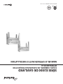
SÉRIEE2000 DE GARLAND
FOURS COMBINÉS, DE CUISSON ÉLECTRIQUE ET DE
RÔTISSAGE DE LA
MANUEL D’OPÉRATION ET D’INSTALLATION
-
 1
1
-
 2
2
-
 3
3
-
 4
4
-
 5
5
-
 6
6
-
 7
7
-
 8
8
-
 9
9
-
 10
10
-
 11
11
-
 12
12
-
 13
13
-
 14
14
-
 15
15
-
 16
16


Garland 36ER33-88 Owner Instruction Manual
- Catégorie
- Fours
- Taper
- Owner Instruction Manual
dans d''autres langues
- English: Garland 36ER33-88
Documents connexes
-
Garland E20 Series Owner Instruction Manual
-
Garland G2772 Mode d'emploi
-
Garland G24 SERIES GAS COUNTER EQUIPMENT & G20 SERIES STOCK POT RANGES Owner Instruction Manual
-
-
Garland Master series Owner Instruction Manual
-
-
-
-
-
