
Version 7/11 - Page 1
READ THESE INSTRUCTIONS BEFORE YOU START INSTALLING THIS RANGEHOOD
WARNING: - TO REDUCE THE RISK OF A RANGE TOP GREASE FIRE: a) Never leave surface units unattended at high
settings. Boilovers cause smoking and greasy spillovers that may ignite. Heat oils slowly on low or medium setting. b)
-
-
published by NFPA.
ALL WALL AND FLOOR OPENINGS WHERE THE RANGEHOOD IS INSTALLED MUST BE SEALED.
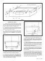
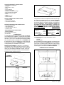
This rangehood requires at least 24" of clearance between the bottom of the rangehood and the cooking surface or countertop.
This minimum clearance may be higher depending on local building code. For example, for gas ranges, a minimum of 30" may
be required. The maximum depth of overhead cabinets is 13". Overhead cabinets on both sides of this unit must be a minimum
of 18" above the cooking surface or countertop. Consult the cooktop or range installation instructions given by the manufacturer
before making any cutouts. MOBILE HOME INSTALLATION The installation of this rangehood must conform to the Manufactured
Home Construction and Safety Standards, Title 24 CFR, Part 3280 (formerly Federal Standard for Mobile Home Construction and
Safety, Title 24, HUD, Part 280).
un élément de la table de cuisson fonctionner sans surveillance à la puissance de chauffage maximale; un renversement/
TOUTE OUVERTURE DANS LE MUR OU LE PLANCHER À PROXIMITÉ DE LA HOTTE DOIT ÊTRE SCELLÉ
Gardez 24 po. de hauteur entre le bas de la hotte et la surface de cuisson. Cette hauteur minimum peut être plus haute suivant le
code municipal. Par exemple, les cuisinières à gaz peuvent requérir 30 po. de hauteur. Les armoires au-dessus ne dépasseront
pas 13 po. de profondeur. Les armoires au-dessus de chaque côté devront être au moins à 18 po. au-dessus de la surface
de cuisson. Consultez la che technique avant de découper les armoires. L'installation de cette hotte doit être conforme aux
Réglements de Manufactured Home Construction and Safety Standards, titre 24 CFR, Section 3280 (anciennement Federal
Standard for Mobile Home Construction and Safety Standards, titre 24 CFR, Section 3280 (anciennement Federal Standard for
Mobile Home Construction and Safety, titre 24, HUD, Section 280).
AGIO
Under Cabinet Tiltout Rangehood
• Installation Instructions
• Use and Care Information
The Installer must leave these instructions with the homeowner.
The homeowner must keep these instructions for future refer-
ence and for local electrical inspectors' use.

Version 7/11 - Page 2
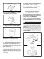
Determine which venting method is best for your application.
Ductwork can extend either through the wall or the roof.
The length of the ductwork and the number of elbows should
be kept to a minimum to provide efcient performance. The
size of the ductwork should be uniform. Do not install two
elbows together. Use duct tape to seal all joints in the ductwork
system. Use caulking to seal exterior wall or oor opening
around the cap.
Flexible ductwork is not recommended. Flexible ductwork
creates back pressure and air turbulence that greatly
reduces performance.
Make sure there is proper clearance within the wall or oor
for exhaust duct before making cutouts. Do not cut a joist or
stud unless absolutely necessary. If a joist or stud must be
cut, then a supporting frame must be constructed.
FOR MORE SPECIFIC DUCTWORK INFORMATION, GO
TO PAGE 4.
Ductwork.
A 120 volt, 60 Hz AC-only electrical supply is required on a separate
15 amp fused circuit. A time-delay fuse or circuit breaker is recom-
mended. The fuse must be sized per local codes in accordance with
the electrical rating of this unit as specied on the serial/rating plate
located inside the unit near the eld wiring compartment. THIS UNIT
MUST BE CONNECTED WITH COPPER WIRE ONLY. Wire sizes
must conform to the requirements of the National Electrical Code,
ANSI/NFPA 70 - latest edition, and all local codes and ordinances.
Wire size and connections must conform with the rating of the appli-
ance. Copies of the standard listed above may be obtained from:
National Fire Protection Association
Batterymarch Park
Quincy, Massachusetts 02269
• Venting system MUST terminate outside
the home.
• DO NOT terminate the ductwork in an attic
or other enclosed space.
• DO NOT use 4" laundry-type wall caps.
• Flexible-type ductwork is not
recommended.
• DO NOT obstruct the ow of combustion
and ventilation air.
• Failure to follow venting requirements may
result in a re.
This appliance should be connected directly to the fused
disconnect (or circuit breaker) through exible, armored or
nonmetallic sheathed copper cable. Allow some slack in the
cable so the appliance can be moved if servicing is ever nec-
essary. A UL Listed, 1/2" conduit connector must be provided
at each end of the power supply cable (at the appliance and
at the junction box).
When making the electrical connection, cut a 1 1/4" hole
in the wall. A hole cut through wood must be sanded until
smooth. A hole through metal must have a grommet.
WARNING - TO REDUCE THE RISK OF FIRE OR ELECTRIC
control device.
-
FOLLOWING: Use this unit only in the manner intended
the manufacturer.
service panel and lock the service disconnecting means
to prevent power from being switched on accidentally.
-
FOLLOWING: Installation Work And Electrical Wiring Must
Construction.
burning equipment to prevent backdrafting. Follow the
standards such as those published by the National Fire
-
age electrical wiring and other hidden utilities.
Ducted fans must always be vented to the outdoors.
WARNING
• Electrical ground is required on this rangehood.
• If cold water pipe is interrupted by plastic,
nonmetallic gaskets or other materials, DO NOT
use for grounding.
• DO NOT ground to a gas pipe.
• DO NOT have a fuse in the neutral or grounding
circuit. A fuse in the neutral or grounding circuit
could result in electrical shock.
• Check with a qualied electrician if you are in doubt
as to whether the rangehood is properly grounded.
• Failure to follow electrical requirements may result
in a re.
WARNING
For residential use only.
!
!
Cold Weather installations
An additional back draft damper should be installed to minimize
backward cold air ow and a nonmetallic thermal break should
be installed to minimize conduction of outside temperatures
as part of the vent system. The damper should be on the cold
air side of the thermal break. The break should be as close as
possible to where the vent system enters the heated portion
of the house.

Version 7/11 - Page 3
Conrmer la sortie d'évacuation - soit par le mur, soit par
le toit.
Utilisez une longueur de tuyauterie minimale avec les moindres
de coudes pour la plus grande efcacité. Le diamètre de
tuyauterie doit être uniforme. N'installez jamais 2 coudes
ensemble. Scellez bien tous les joints avec un ruban adhésif
métallique à l'intérieur et scellez bien le clapet extérieur avec
du calfeutrage.
performance.
Veillez à ce que l'espace pour le tuyau soit ample - ainsi on
n'aurait pas besoin de découper les supports de mur intérieur.
Si ce découpage est nécessaire, veillez bien à ce qu'un
renforcement soit mis en place.
RÈGLEMENTS D'ÉVACUATION ADDITIONELL -
PAGE 9.
Seulement Les Matériaux Métalliques.
exiblle couvert en cuivre en laissant un peu de lâchement dans
le l pour permettre le déplacement de l'appareil. Veillez a ce
qu'un contact d'un demi-pouce (1/2 po.) soit installé à chaque
bout de l (soit à l'appareil ainsi qu'à la boite à fusible).
Faites un trou de 1 1/4 po. dans le mur. S'il s'agit d'un trou en
bois - sablez-le bien, tandis qu'un trou passant par le métal
demande un bouche-trou.
de vitesse à semi-conducteurs.
et entre en communication avec lui pour toute
information.
reste fermé. Si on ne peut pas verrouiller le panneaux
porte.
Les Codes Municipaux.
mesures de sécurité du fournisseur tels que ceux publiés
codes municipaux.
électrique. Une ventilateur à évacuation extérieure doit
• Le système d'évacuation DOIT sortir à l'extérieur.
• N'ÉVACUEZ PAS le conduit soit dans une
mansarde soit dans un espace enfermé.
• N'UTILISEZ PAS un clapet de séchoir à 4 pouces.
• N'utilisez pas un conduit exible.
• N'ENCOMBREZ PAS la circulation d'air.
• Faute de suivre cet avertissement pourrait
occasionner un feu.
Le raccordement électrique doit se faire avec un circuit séparé
de 15 ampères fusible à 120V, 60 Hz, courant alternant. On
recommande un coupe-circuit. La taille du fusible doit se
conformer aux codes municipaux suivant la spécication
électrique sur la plaque intérieure. Le diamètre du l
devra aussi se conformer aux règlements du code national
électrique, ANSI/NFPA 70 - ainsi qu'aux règlements locaux
et les spécications de cet appareil. On peut obtenir ces
informations chez:
l'Association Nationale de la Prévention du Feu
Batterymarch Park
Quincy, Massachusetts 02269
Raccordez cet appareil directement au coupe-circuit avec un l
• Une prise à terre est nécessaire pout cette hotte.
• N'utilisez pas un tuyau à l'eau froide pour la mise
à terre s'il est branché à un joint plastique, non-
métallique ou autre.
• NE JOIGNEZ PAS la mise à terre à conduit de gaz.
• N'INSTALLEZ PAS un fusible dans le circuit de
mise à terre - ce qui peut causer une secousse
électrique.
• Vériez avec un électricien certié à ce que la hotte
soit bien mise à terre.
• Faute de suivre ces recommandations pourrait
occasionner un feu.
Uniquement pour usage menager.
!
!
Installations pour régions à climat froid
On devrait installer un clapet antireux additionnel pour minimiser le
reux d'air froid, et incorporer un élément non métallique d'isolation
thermique pour minimiser la conduction de chaleur par l'intermédiaire
du conduit d'évacuation, de l'intérieur de la maison à l'extérieur.
Le clapet anti-reux doit être placé du côté air froid par rapport à
l'élément d'isolation thermique. L'isolant thermique doit être aussi
proche que possible de l'endroit où le système d'évacuation s'introduit
dans la partie chauffée de la maison.

Version 7/11 - Page 4
TOOLS NEEDED FOR INSTALLATION
• Saber Saw or Jig Saw
• Drill
• 1 1/4" Wood Drill Bit
• Pliers
• Phillips Screwdriver
• Flat Blade Screwdriver
• Wire Stripper or Utility Knife
• Metal Snips
• Measuring Tape or Ruler
• Level
• Pencil
• Caulking Gun
• Duct Tape
PARTS SUPPLIED FOR INSTALLATION
• 1 Backdraft Damper
• 4 Black Screws & 4 Silver Screws
• 1 Literature Package
PARTS NEEDED FOR INSTALLATION
• 2 Conduit Connectors
• Power Supply Cable
• 1 Wall or Roof Cap
• All Metal Ductwork
• Charcoal Filters
For non-vented installations only,
replace charcoal lters as needed
part # FILTER3
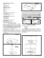
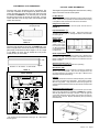
PLAN THE DUCTWORK
The Agio convertible rangehood is designed to offer wide
exibility of installations. The rangehood can be ducted
vertically or horizontally through a 3 1/4" X 10" rectangular
vent. The unit can also be installed in a ductless recirculating
conguration. FIGURES 1 and 2 show horizontal and vertical
duct installations for this rangehood. shows the
exhaust opening for ductless installation.
HORIZONTAL
DUCTING
DUCTING
DUCTLESS
INSTALLATION
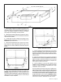
CALCULATE THE DUCTRUN LENGTH
The ductrun should not exceed 25 equivalent feet if ducted with the
required minimum of 3 1/4" by 10" rectangular duct. Calculate the
length of the ductwork by adding the equivalent feet in FIGURE 4
for each piece of duct in the system. An example is given in FIGURE
5.
sure that there is a minimum
elbows if more than one is used. Do not install two elbows
together.far away from
FIGURE 4
45˚ Elbow
90˚ Elbow
90˚ Flat Elbow
Wall Cap
3.0 feet
5.0 feet
12.0 feet
0.0 feet
9 Feet Straight Duct
2 - 90˚ Elbows
Wall Cap
Total System
9.0 feet
10.0 feet
0.0 feet
19.0 feet
FIGURE 5
PLAN THE DUCTWORK
First, determine which venting option will be used:
• Horizontal
• Vertical
• Ductless
For Horizontal and Vertical ducting, the ductwork cutout dimensions
are given in FIGURE 6. For ductless installations, read the section
discussing ductless installations before you make any cutouts or
modications to the rangehood. Ductless installations require
Charcoal Filters.
FIGURE 6
30" or 36" or 23 5/8" (60 cm)
30" or 36" or 23 5/8" (60 cm)
FIGURE 1
FIGURE 2
Pre-Planning Your Installation -
Important: The
recommended height to install this hood off the cooktop
is a minimum of 24" and a maximum of 30” for maximum
effectiveness. Also consult the cooktop manufacturer’s
recommendation.

Version 7/11 - Page 5
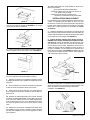
PREPARE THE CABINET
1. Disconnect and move freestanding range from cabinet
opening to provide easier access to upper cabinet and rear
wall. Put a thick, protective covering over cooktop, set-in
range or countertop to protect from damage or dirt.
2. Determine and clearly mark with a pencil the center line
of the cabinet on the wall and on the underside of the cabinet
where the rangehood will be installed.
The Agio attaches to the cabinet by four black screws.
Mark the cabinet and insert the screws into the underside
of the cabinet as shown in FIGURE 8. Do not tighten the
screws.
INSTALL THE RANGEHOOD
1. Remove the unit from the carton and place on a at
surface for assembly. Make sure to cover the surface to
prevent accidental damage. Remove all parts including the
Backdraft Damper, Screws, and Literature Package before
discarding the carton.
2. Remove both grease lters from the unit and set aside.
The rangehood is shipped from the factory with the backdraft
damper attached inside. Using a Phillips head screwdriver,
remove the backdraft damper by loosening the screw marked
with a red dot on top of the rangehood.
Before installing, the rangehood must be adjusted for
venting. For ductless installations, read the following section
which discusses special requirements for these installations
before continuing.
For Horizontal or Vertical ducting, the respective exhaust
knockout must be removed. Each knockout is attached to the
rangehood by four points. Using a at blade screwdriver or
utility knife, remove the exhaust knockout. Save this plate as
it must be used to block the ductless exhaust grill. FIGURE
shows the location of the knockouts for both horizontal
and vertical. ONLY ONE must be removed.
30" or 36" or 23 5/8" (60 cm)
30" or 36" or 23 5/8" (60 cm)
30" or 36" or 23 5/8" (60 cm)
FIGURE 7
FIGURE 8
4. Determine the proper cutouts for the ductwork. Make
all necessary cuts in the walls or cabinets for the ductwork.
Install the ductwork before mounting the rangehood.
5. Determine the proper location for the Power Supply
Cable. Both possible locations are given in . Use
a 1 1/4" Drill Bit to make this hole. Run the Power Supply
Cable. Use caulking to seal around the hole. DO NOT turn
on the power until installation is complete.

Version 7/11 - Page 6
6. Reattach the control box and support. Make sure that
the wiring harness is concealed behind the support.
7. Remove the eld wiring compartment cover. Feed the
Power Supply Cable through the electrical knockout.
8. Attach the backdraft damper to the proper exhaust open-
ing using two silver screws supplied with the rangehood.
Attach the rangehood to the cabinet bottom. The four
key holes slip onto the four screws mounted to the cabinet
bottom. Tighten the screws.
Connect the Power Supply Cable to the rangehood.
Attach the White lead of the power supply to the White lead
of the rangehood with a twist-on type wire connector. Attach
the Black lead of the power supply to the Black lead of the
rangehood with a twist-on type wire connector. Connect
the Green (Green and Yellow) ground wire under the Green
grounding screw.
4. Remove the central support and control box by remov-
ing the screws indicated in FIGURE 11. It is not necessary
to remove the blower to perform this operation.
5. Attach the cover behind the exhaust grate with two silver
screws supplied with the rangehood as indicated in FIGURE 12.
11. Replace the eld wiring compartment cover. For duct-
less installations, refer to the next section which discusses
ductless installations. Replace the grease lters.
12. Turn the power supply on. Turn on blower and light.
IF THE RANGEHOOD DOES NOT OPERATE:
• Check that the circuit breaker is not tripped or the
house fuse blown.
• Disconnect the power supply and check that the
wiring connections have been made properly.
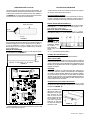
DUCTLESS INSTALLATIONS
For ductless installations, the blower must be positioned with
the exhaust pointing forward ( so that the exhaust exits from
the front grill ) before attaching the rangehood to the cabinet.
Ductless installations require Charcoal Filters.
1. Remove both grease lters, the central support and the
control box. Remove the two thumb screws on either side of
the blower and remove the blower from the mounting guides
as indicated in FIGURE 11.
2.
.
Then Rotate the blower 180° so that the exhaust points out
the front of the rangehood. Replace the black lter holders
and the two thumb screws and tighten so that the blower
is securely fastened inside the rangehood as indicated in
. Reattach the control box and central support.
Make sure that the wiring harness is concealed behind the
central support.
For ductless installations, Charcoal Filters are required
and must be installed before the grease lters are replaced.
The charcoal lters attach to both ends of the blower as
indicated in FIGURE 14.
FIGURE 11
FIGURE 12
FIGURE 14
A
A

Version 7/11 - Page 7
Three Screws
Rangehood Body
Front
Strip
CUSTOMIZING YOUR RANGEHOOD
The front strip of the rangehood can be customized. The
front strip is attached to the rangehood by three recessed
screws and three key hole slots on the back side of the strip
as indicated in FIGURE 15. It is necessary only to remove
the three lower screws to remove the front strip. The top
screws will slide out of the key holes once the three lower
screws are removed.
The front strip dimensions are given in FIGURE 16. If you
wish to keep the frame of the front panel and only replace the
glass panel, the dimensions follow: Height = 5 11/16", Depth
= 1/8", Width = 29 11/16" (for 30" model) 35 11/16" (for 36"
model) 23 5/8" (for 24" model).
FIGURE 16
WIRING DIAGRAM
• This rangehood uses Flourescent Lamp Type 18", 15W T8 and
Starter Type S2.
Rangehood Control Panel
All controls are located under the front panel and are shown in
FIGURE 17.
On/Off switch for the uorescent light. Moving the switch to the
1 Position turns the light On. Moving the switch to the 0 Position
turns the light Off.
FIGURE 15
FIGURE 17
FIGURE 18
Controls blower speed. Moving the switch to the 1 Position turns
the blower on LOW. Moving the switch to the 2 Position turns the
blower on MEDIUM. Moving the switch to the 3 Position turns the
blower on HIGH.
Red light will be on when the rangehood is operating.
When the front panel of the rangehood is closed, the rangehood
will turn off by a microswitch. This turns the rangehood On and
Off without adjusting the switches for the Light or Blower and it
remembers the last speed setting.
Cleaning
The metal grease lters should be cleaned frequently in hot deter-
gent solution or placed in the dishwasher. Clean exterior surfaces
with hot soapy water. Using abrasives and scouring agents can
scratch rangehood nishes and should not be used to clean nished
surfaces.
Replacing the Fluorescent Light
To replace the uorescent light, remove the retainer clips from both
ends of the glass diffuser as indicated in FIGURE 18. Carefully
slide the glass diffuser all the way to the left. Lower the right end
of the glass below the support ange, then remove the glass by
sliding it back to the left. Replace the diffuser glass by reversing
these directions.
23 5/8" or 29 15/16" or 35 15/16"
5 7/8"
13/16"
USE AND CARE INFORMATION
This rangehood system is designed to remove smoke, cooking
vapors and odors from the cooktop area.
For Best Results
Start the rangehood several minutes before cooking to develop proper
airow. Allow the unit to operate for several minutes after cooking
is complete to clear all smoke and odors from the kitchen.
Blower On/Off
On/Off switch for the
blower. Moving the
switch to the 1 Posi-
tion turns the blower
On. Moving the switch
to the 0 Position turns
the blower Off.

Version 7/11 - Page 8
All Faber products are warranteed against any defect in materials or workmanship for the
original purchaser for a period of 1 year from the date of original purchase. This warranty
covers labor and replacement parts. To obtain warranty service, contact the dealer from
whom you purchased the rangehood, or the local Faber distributor. If you cannot identify
a local Faber distributor, contact us at (508) 358-5353 for the name of a distributor in your
area.
1. Service calls to correct the installation of your range hood, to instruct you how to use your
range hood, to replace or repair house fuses or to correct house wiring or plumbing.
2. Service calls to repair or replace range hood light bulbs, fuses or lters. Those
consumable parts are excluded from warranty coverage.
3. Repairs when your range hood is used for other than normal, single-family
household use.
4. Damage resulting from accident, alteration, misuse, abuse, re, ood, acts of God,
improper installation, installation not in accordance with electrical or plumbing codes, or
use of products not approved by Faber.
5. Replacement parts or repair labor costs for units operated outside the United States or
Canada, including any non-UL or C-UL approved Faber rangehoods.
6. Repairs to the hood resulting from unauthorized modications made to the
rangehood.
7. Expenses for travel and transportation for product service in remote locations and pickup
and delivery charges. Faber range hoods should be serviced in the home.
Record Your Information Below:
Serial #: __________________________
Date of Purchase: ______________

Version 7/11 - Page 9
CONDUIT
HORIZONTAL
CONDUIT
FIGURE 4
Coude 45˚
Coude 90˚
Coude plat 90˚
Capuchon de mur
3,0 pi
5,0 pi
12,0 pi
0,0 pi
9 pi de conduit droit
2 Coudes 90˚
Capuchon de mur
Système total
9,0 pi
10,0 pi
0,0 pi
19,0 pi
FIGURE 5
• Scie sauteuse ou à découper
• Perceuse
• Mèche à bois 1 1/4 po
• Pinces
• Tournevis Phillips
• Tournevis à lame plate
• Dénude l ou couteau tout usage
• Pince coupante à l métallique
• Ruban à mesurer ou règle
• Niveau
• Crayon
• Outil à calfeutrage
• Ruban à conduit
• 1 registre à clapet
• 4 vis noir & 4 vis argenté
• 1 nécessaire d’instructions
• 2 connecteurs de conduit
• Câble d’alimentation
• 1 capuchon de mur ou de toit
• Conduit en métal
Pour installation sans conduit
part # FILTER3
PLANIFICATION
La hotte mixte Agio est conçue de façon à offrir un maximum
de possibilités pour l’installation. La hotte peut être installée
avec un conduit horizontal ou vertical par un évent rectangu-
laire de 3 1/4 po x 10 po. Cette hotte peut aussi être installée
sans conduit de façon à recirculer l’air. Les FIGURES 1 et
2 démontrent les types d’installation de conduit vertical et
horizontal pour cette hotte. La montre l’ouverture
d’échappement pour l’installation sans conduit.
CALCUL DE LONGUEUR DU CONDUIT
La longueur du conduit ne doit jamais excéder 25 pi s’il s’agit
de conduit rectangulaire de 3 1/4 po. Calculer la longueur
du conduit en ajoutant l’équivalent en pied de la FIGURE 4
pour chaque pièce du conduit du système. Un exemple est
donné à la FIGURE 5.
y ait un minimum de 24 po de conduit droit entre les
Ne pas installer
deux coudes ensemble.
CHOISIR LE CONDUIT
Premièrement, choisir le type d’évacuation désiré :
• Horizontal
• Vertical
• Sans conduit
Pour l’installation horizontale et verticale, les dimensions de
la coupe sont indiquées à la FIGURE 6. Pour les installations
sans conduit, consulter la section traitant de ce sujet avant de
faire toute coupe ou modication à la hotte. L’installation sans
conduit exige un nécessaire des Filtres au Charbon.
30" or 36" or 23 5/8" (60 cm)
30" or 36" or 23 5/8" (60 cm)
FIGURE 2
FIGURE 1
FIGURE 6
SANS CONDUIT
- Important : La hauteur re-
commandée pour installer cette hotte au-dessus de la sur-
face de cuisson est d’un minimum de 24” et d’un maximum
de 30” pour un maximum d’efcacité. De plus, nous vous
recommandons consulter le manuel de recommandations
du fabricant de la surface de cuisson.

Version 7/11 - Page 10
1. Débrancher et déplacer la cuisinière de l’ouverture an
d’avoir un meilleur accès aux armoires supérieures et au
mur arrière. Placer un recouvrement épais sur la plaque de
cuisson, la cuisinière encastrée ou le dessus du comptoir
pour protéger des dommages et de la poussière.
2. Déterminer et marquer clairement, à l’aide d’un crayon,
la ligne centrale sur le mur et sur le côté inférieur de l’armoire
où la hotte sera installée.
La hotte Agio se xe à l’armoire avec quatre vis noir.
Marquer l’armoire et placer les vis tel qu’il est indiqué à la
FIGURE 8. Ne pas serrer les vis.
4. Déterminer l’emplacement de la coupe pour le conduit.
Faire toutes les coupes nécessaires dans les murs ou les
armoires pour le conduit. Installer le conduit avant de poser
la hotte.
5. Déterminer l’emplacement approprié pour le câble d’ali-
mentation. Deux emplacements possibles sont illustrés à la
. Utiliser une mèche de 1 1/4 po pour faire un trou
et y passer le câble d’alimentation. Utiliser du calfeutrage pour
sceller tout autour du trou. NE PAS mettre en circuit tant que
l’installation n’est pas complétée.
INSTALLATION DE LA HOTTE
1. Retirer l’appareil de la boîte et le déposer sur une surface
plate pour l’assemblage. Couvrir la surface pour éviter tout
dommage accidentel. Retirer toutes les pièces incluant 1
registre à clapet, les vis, et le nécessaire d'instructions avant
de jeter la boîte.
2. Retirer les deux ltres pour la graisse de l’appareil et
les mettre de côté. La hotte est expédiée de l’usine avec un
registre de tirage à volet xé à l’intérieur. Avec un tournevis
Phillips, retirer le registre en dévissant les vis marquées d’un
point rouge sur le dessus de la hotte.
Avant l’installation, la hotte doit être ajustée pour la
ventilation. Pour les installations sans conduit, lire la section
suivante qui traite des exigences spéciales pour ce type
d’installation avant de continuer.
Pour les conduits horizontaux et verticaux, la pastille enfon-
çable doit être enlevée. Chaque pastille est maintenue à la
hotte en quatre points. Utiliser un tournevis à lame plate ou
un couteau tout usage, retirer la pastille enfonçable. Con-
server cette pièce car elle doit servir à maintenir en place
la grille d’évacuation sans conduit. La indique
l’emplacement des pastilles enfonçables pour les modèles
horizontaux et verticaux. UNE SEULE doit être enlevée.
30" or 36" or 23 5/8" (60 cm)
30" or 36" or 23 5/8" (60 cm)
30" or 36" or 23 5/8" (60 cm)
FIGURE 7
FIGURE 8

Version 7/11 - Page 11
6. Réinstaller la boîte de contrôle et le support. S’assurer
que le l conducteur soit caché derrière le support.
7. Retirer le couvercle du compartiment de lage. Passer
le câble d’alimentation par la pastille enfonçable de la boîte
électrique.
8. Fixer le registre sur l’ouverture d’évacuation appropriée
à l’aide de deux vis argenté fournies avec la hotte.
Fixer la hotte au bas de l’armoire. Les quatre fentes à
trous s’insèrent sur les quatre vis xées au bas de l’armoire.
Serrer les vis.
Brancher le câble d’alimentation sur la hotte. Attacher
le l blanc du câble d’alimentation sur le l blanc de la hotte
avec une cosse. Attacher le l noir du câble d’alimentation
au l noir de la hotte avec une cosse. Brancher le l de mise
à la terre vert (jaune et vert) sous la vis de mise à la terre
verte.
11. Replacer le couvercle du compartiment de lage. Pour
les installations sans conduit, consulter la section suivante
qui traite des installations sans conduit. Replacer les ltres
pour la graisse.
4. Retirer le support central et la boîte de contrôle en enle-
vant les vis tel qu’il est indiqué à la FIGURE 11. Il n’est pas
nécessaire de retirer le ventilateur.
5. Fixer le couvercle derrière la grille d’évacuation à l’aide de
deux vis argenté fournies avec la hotte. Voir la FIGURE 12.
12. Mettre l’alimentation en circuit. Mettre en circuit le ven-
tilateur et la lumière.
SI LA HOTTE NE FONCTIONNE PAS :
• Vérier si le disjoncteur n’est pas hors tension ou
si un fusible n’est pas grillé.
• Débrancher l’alimentation et vérier si les
connexions ont été faites de façon adéquate.
INSTALLATIONS SANS CONDUIT
Les installations sans conduit requièrent le nécessaire sans
conduit. Le ventilateur doit être placé de façon à ce que
l’évacuation se fasse vers l’avant (l’évacuation sera faite par
la grille avant) avant de xer la hotte à l’armoire. Les instal-
lations sans conduit requièrent un nécessaire des Filtres
au Charbon.
1. Retirer les deux ltres pour la graisse, le support central
et la boîte de contrôle. Enlever les deux écrous à oreilles de
chaque côté du ventilateur et retirer le ventilateur des guides
de montage tel qu’il est indiqué à la FIGURE 11.
2.
sur chaque extrémité du ventilateur en enle-
Tourner le ventilateur sur 180º de façon à ce
que l’évacuation se fasse vers l’avant de la hotte. Rempla-
cez les supports noirs de ltre, Replacer les deux écrous à
oreilles de chaque côté du ventilateur et serrer de façon à
ce que le ventilateur soit xé solidement à l’intérieur de la
hotte, tel qu’il est indiqué à la . Replacer la boîte
de contrôle et le support central. S’assurer que le lage soit
caché derrière le support central.
Deux Filtres au Charbon sont requis pour les installa-
tions sans conduit (pièce nos 6093032) et doivent être posés
avant que les ltres pour la graisse ne soient replacés. Les
ltres au charbon se placent à chaque extrémité du
ventilateur. Voir FIGURE 14.
FIGURE 14
FIGURE 12
FIGURE 11
A
A

FIGURE 16
DIAGRAMME DE FILAGE
• Cette hotte utilise une ampoule uorescente, type 18", 15W
T8 et un déclencheur, type S2.
PERSONNALISER LA HOTTE
La bande frontale de la hotte peut être personnalisée. La
bande frontale est maintenue à la hotte par trois vis creuses
et trois fentes à l’arrière de la bande comme il est indiqué à
la FIGURE 15. Les vis du dessus glisseront hors des fentes
lorsque les trois vis creuses seront enlevées.
Les dimensions de la bande sont données à la FIGURE 16.
Si vous désirez retenir la charpente de la bande frontale, et
seulement replacer le verre, les dimensions sont Hauter =
5 11/16 po, Épaisseur = 1/8 po, Largeur = 29 11/16" (pour
modèle 30 po) 35 11/16 po (pour modèle 36 po) 23 5/8 po
(pour modèle 24 po).
Panneau de commandes
Toutes les commandes sont situées sous le panneau avant
et sont illustrées à la FIGURE 17.
Interrupteur marche-arrêt pour la lumière uorescente. Régler
l’interrupteur à « 1 » pour mettre en circuit (ON) et à « O »
pour mettre hors circuit (OFF).
Réglage de la vitesse. Régler l’interrupteur à « 1 » pour vi-
tesse basse (LOW); à « 2 » pour vitesse moyenne (MEDIUM);
et « 3 » pour vitesse élevée (HIGH).
La lumière sera rouge lorsque la hotte fonctionne.
Lorsque le panneau frontal de la hotte est fermé, la hotte se
fermera par un micro contact. Ceci met la hotte en circuit (ON)
et hors circuit (OFF) sans ajustement des interrupteurs de la
lumière ou du ventilateur et la hotte se rappellera du dernier
réglage de vitesse.
Nettoyage
Les ltres à graisse en métal devraient être nettoyés fré-
quemment dans une solution d’eau chaude et de détergent
ou mettre au lave-vaisselle. Nettoyer les surfaces extérieu-
res à l’eau chaude savonneuse. Ne pas utiliser de produits
abrasifs ou de récurants, car ils peuvent égratigner le ni en
acier inoxydable et ils ne devraient pas être employés pour
nettoyer les surfaces de nition.
Pour remplacer la lumière uorescente enlever les pinces
de retenu aux deux extrémités du diffuseur en verre qu’il est
indiqué à la FIGURE 18.
Bande
frontale
Boîtier de la hotte
Trois vis
FIGURE 15
FIGURE 18
23 5/8" or 29 15/16" or 35 15/16"
5 7/8"
13/16"
FIGURE 17
UTILISATION ET ENTRETIEN
Cette hotte est conçue pour enlever la fumée, les vapeurs
de cuisson et les odeurs de la cuisine.
Pour de meilleurs résultats
Mettre la hotte en circuit avant de commencer la cuisson.
Laisser l’appareil fonctionner quelques minutes après la
cuisson pour éliminer la fumée et les odeurs de la cuisine.
Bouton marche-
arrêt du ventila-
Interrupteur mar-
che-arrêt pour le
ventilateur. Régler
en position « 1 »
pour mettre en
circuit (ON) et en position « O » pour mettre hors circuit
(OFF).
Glisser prudemment le
diffuseur en verre com-
plètement vers la gau-
che. Abaisser le côté
droit du verre sous le
rebord, enlever le verre
en le glissant de nou-
veau vers la gauche.
Replacer le diffuseur
en verre en inversant la
marche à suivre.
Version 9/07 - Page 12

FABER
)
Faber garantit à l’utilisateur-acheteur d’origine que les produits Faber vendus neufs par nous sont sans vice de
matériel et de main-d’oeuvre d’origine pour une période d’un an à partir de la date d’achat. La garantie couvre
la main-d’oeuvre et les pièces de remplacement. An d’obtenir un service sous garantie, communiquer avec le
marchand où la hotte a été achetée ou le distributeur Faber de la région. Si l’on ne peut trouver de distributeur
Faber, communiquer avec nous au (508) 358-5353 an d’obtenir le nom d’un distributeur dans la région.
Les frais suivants ne sont pas couverts par la garantie Faber :
1. Les appels de service pour corriger l’installation de votre hotte de cuisinière, pour vous indiquer
comment utiliser votre hotte de cuisinière, pour remplacer ou réparer les fusibles de votre maison ou
pour corriger votre câblage ou votre système de plomberie.
2. Les appels de service pour remplacer ou réparer les ampoules, les fusibles ou les
ltres de votre hotte de cuisinière.
3. Les réparations lorsque votre hotte de cuisinière a été utilisée plus que la normale,
c'est-à-dire plus que pour une famille par foyer.
4. Les dommages résultant d’un accident, de l’altération, d’une mal utilisation, d’un acte
de Dieu, d’une installation inappropriée, d’une installation non-conforme aux
normes d’électricité ou de plomberie ou d’une utilisation de l’appareil non approuvée par Faber.
5. Les pièces de remplacement ou les frais de main d’œuvre pour les unités
utilisées en dehors du Canada ou des États Unis, incluant toutes hotte de cuisinière
approuvée par Faber non UL ou C-UL.
6. Les réparations dues à des modications non-autorisées sur votre hotte de cuisinière.
7. Les frais de transport de l’appareil pour réparations à distance.
Séquentiel #: __________________________
Version 9/07 - Page 13
-
 1
1
-
 2
2
-
 3
3
-
 4
4
-
 5
5
-
 6
6
-
 7
7
-
 8
8
-
 9
9
-
 10
10
-
 11
11
-
 12
12
-
 13
13


Faber AGIO24BK Guide d'installation
- Catégorie
- Hottes
- Taper
- Guide d'installation
dans d''autres langues
- English: Faber AGIO24BK Installation guide
Documents connexes
-
Faber Agio Manuel utilisateur
-
-
-
-
-
-
-
-
-