Automatic Technology Garage Door Lock Manuel utilisateur
- Taper
- Manuel utilisateur

Garage Door Lock Installation Instructions
Auto-Lock Kit
Doc # 160070_00
Part # 79171
Released 09/03/22
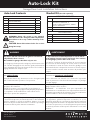
GARAGE DOOR LOCK - ORDER NO. 100040
ITEM DESCRIPTION QTY
1 GARAGE DOOR LOCK 1
2 COUNTERSUNK HEAD SCREW ZN M6 X 14 2
3 TAPTITE “P” BLACK SCREW M3 X 12 4
4 BATTERY C-LR14 2
5 WIRELESS BASE STATION MODULE 1
6 DRILLING TEMPLATE LABEL 1 FASTENER PACK
ITEM DESCRIPTION QTY
10 FLANGE HEAD TEK SCREWS 20 X 25 CL4 4
11 MUSHROOM HEAD BOLTS 1/4” - 20 X 1/2” 3
12 FLANGE NUT 1/4” 3
DOOR BRACKET KITS
ITEM STRIKER BRACKET FOR DOOR: KIT
7 PANELIFT, PANELIFT GEN II, PANELIFT ICON,
PANELMASTA, FIRMAPANEL, P7,
DESIGN-A-DOOR, ENVIROPANEL, SMOOTH-
PANEL & TOUGHPANEL
MC0104
8 STORMSHIELD MC0105
9 TONGUE AND GROOVE MC0106
Auto-Lock Contents Bracket Kit (Kit sold separately)
WARNING! Ensure the opener is not engaged
when the Auto-lock is being used with only the bolt
unit. Failure to do so may void the warranty of the
opener.
CAUTION: Ensure bolt on Auto-lock is free to move
during limit setup.
WARNING! AVERTISSMENT
This device will slide a bolt into the guide track automati-
cally when the door is closed.
Not suitable for garages that have only one exit.
For emergency release press the emergency unlock button on the
lock. This will disengage the lock from the guide track and allow
you to disengage the opener and open the door. The lock will re-
engage after the next complete cycle.
Ce dispositif insèrera automatiquement un verrou dans le
rail de guidage lorsque la porte sera fermée. Il ne convient
pas aux garages pourvus d’une seule sortie.
Pour activer le système de déverrouillage de secours, appuyez
sur le bouton de déverrouillage de secours situé sur le verrou.
Ceci entraînera le retrait du verrou du rail de guidage et vous
permettra de libérer le dispositif d’ouverture et d’ouvrir la porte.
Le verrou sera de nouveau activé au terme du prochain cycle
complet.
It is our strong recommendation that your operator be fitted
with SAFETY BEAMS.
Safety Beams detect any obstructions in the door/gate’s path
and override automatic operation if one presents.
Nous vous recommandons vivement d’équiper votre dispositif
d’ouverture de FAISCEAUX DE SÉCURITÉ.
Ceux-ci détectent tout obstacle sur le chemin de la porte/du
portail et prennent le relais du mode automatique si le passage
n’est pas dégagé.
For USE ONLY with the following garage door
operators: ATS-2 & ATS-3.
NOTE: The grantee is not responsible for any changes or
modifications not expressly approved by the party responsible
for compliance. Such modifications could void the user’s
authority to operate the equipment.
Conçu pour être utilisé uniquement avec les ouvre portes de
garage suivants : ATS-2 et ATS-3
REMARQUE : Le Bénéficiare n’est pas responsable des
transformations ou modifications non expressément autorisées
par la partie responsable de la conformité. De telles modifications
peuvent invalider le droit à utliser l’équipment.
To comply with FCC/IC RF exposure limits for general population
/ uncontrolled exposure, the antenna(s) used for this transmitter
must be installed to provide a separation distance of at least
20cm from all persons and must not be co-located or operating in
conjunction with any other antenna or transmitter.
Pour respecter les limites d’exposition de la FCC/IC RF relatives
à la population générale/l’exposition incontrôlée, la ou les
antenne(s) utilisée(s) pour cet émetteur doi(ven)t être installée(s)
de façon à garantir une distance de séparation d’au moins 20cm
avec toutes les personnes, et ne doi(ven)t pas être positionnée(s)
ou utilisée(s) au même endroit qu’une autre antenne ou un autre
émetteur.

Auto-Lock Installation Instructions
2
WARNING! AVERTISSMENT
• DO NOT attempt to disassemble, repair or modify the
product.
This will invalidate the warranty.
• DO NOT allow children to play with the Auto-Lock.
• DO NOT install in garages that have only one exit.
• DO NOT cover, paint or lubricate the product.
Ce dispositif insèrera automatiquement un verrou dans le
rail de guidage lorsque la porte sera fermée. Il ne convient
pas aux garages pourvus d’une seule sortie.
Pour activer le système de déverrouillage de secours, appuyez
sur le bouton de déverrouillage de secours situé sur le verrou.
Ceci entraînera le retrait du verrou du rail de guidage et vous
permettra de libérer le dispositif d’ouverture et d’ouvrir la porte.
Le verrou sera de nouveau activé au terme du prochain cycle
complet.
CAUTION: ATTENTION:
BURNS
• DO NOT handle damaged or leaking batteries
• The Auto-Lock Kit contains sealed lead-acid batteries that
must be disposed of properly at the end of their useful life.
MUSCLE STRAIN
• DO NOT attempt to lift the door manually when the Auto-lock
is engaged.
CHUTE DE L’ÉCHELLE
• Vérifiez que l’échelle est adaptée à ce travail.
• Veillez à ce que l’échelle repose sur un sol plat.
• Lorsque l’utilisateur se tient sur l’échelle, veillez à ce que les
points de contact soient au nombre de trois.
BRÛLURES
• NE PAS manipuler des piles endommagées ou qui coulent
• Le kit de verrouillage automatique contient des piles plomb-
acide scellées qui doivent être correctement éliminées au
terme de leur vie utile.
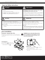
Important Safety Instructions
prior to installation
Preparation - setting the door limits
Ensure the door limits have been set on the opener, prior
to installing the Auto-lock. Refer to the opener manual for
instructions.
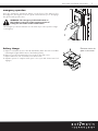
install batteries
a. Insert batteries 4 into drive unit.
b. Place cover back on drive unit and
secure with 4 x screws 3.
4
3
WARNING! remove all manual locking systems
prior to installing lock. Any damage as a result
of a manual lock will void the warranty for the
door, Auto-lock and opener.
program lock
a. Press and hold the info button i on drive unit
until the light goes red.
b. Then press the lock/unlock button to test the
drive unit.

3
Auto-Lock Installation Instructions
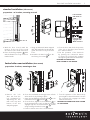
standard installation (side mount)
preparation - no brackets, mounting on track
1
2
a. With the door closed, mark the
position of the top of the second
door wheel on the inside of the track.
b. Place the drilling template 6 label
with the Datum line on top of the line
marked inside.
c. Using an 6mm and 18mm stepped
drill, drill marked holes through the
guide and remove any burs from
holes.
d. Assemble the Autolock 1 to the
track using 2 x screws 2,
lock bolt flush
with inside of
guide
lock bolt when
engaged with
10mm clearance
e. Close the door and check the position
of the lock to the wheel, there should
be a 10mm clearance.
f. Test the operation of the AutoLock
by pressing the lock/unlock button
to ensure the lock bolt fully engages
through the guide without interference.
PROCEED TO CONNECTING
BASE STATION TO THE OPENER.
limited side room installation (door mount)
preparation - brackets, mounting on door
10
11
12
1
6
a. Remove the lock
drive unit from the
lock mechanism by
depressing the two
tabs on the top and
bottom of the unit
and pulling apart.
b. Close door and mark mounting position of both
striker and lock, by holding in place.
c. Open door and affix the striker bracket 6 to the
track with 3 x bolts 11 and nuts 12 .
d. Close the door, align the lock mechanism 1 on
the bottom panel door stile so that the lock bolt
engages fully into the striker bracket 6 and fix
using 4 x flange head tek screws 10 .
e. Fit the lock drive unit to the lock mechanism.
f. Test the operation of the AutoLock by
pressing the lock/unlock button to ensure
the lock bolt fully engages the striker
without interference.
PROCEED TO CONNECTING BASE STATION
TO THE OPENER.

Auto-Lock Installation Instructions
4
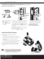
StormShield and Tongue & Groove installation (kits sold separately)
preparation - mounting on door stile
3
1
8
a. Fit the mounting bracket
8 or 9 to the lock
mechanism 1 using 2 x
countersunk head screws
M6 x 14 3.
9
e. Test the operation of the AutoLock
by pressing the lock/unlock button
to ensure the lock bolt fully engages
the striker without interference.
PROCEED TO CONNECTING
BASE STATION TO THE OPENER.
10
11
12
b. Close the door to determine mounting position
between the reinforcing braces on the bottom
door panel and mark. Mount the bracket and
lock mechanism as marked with the 4 flange
head tek screws 20 x 25 CL4 10 , however do
not fully tighten as further final adjustment may
be required.
c. With the door in the closed position align the
striker bracket with the lock
d. Drill 3 x ¼ holes as marked in the tracklock and
fix with 3 x bolts 11 and nuts 12 .
a. Disconnect the power supply to the opener.
b. For ATS-3AM:
i. Remove the left hand side pocket from the opener.
ii. Reach inside the opener and pull out the 4 pin harness
and connect to the wireless basestation module.
For ATS-2AM:
iii. Remove back cover to expose control board.
iv. Reach inside the opener and pull out the 4 pin harness
and connect to the wireless basestation module.
c. Place the module into the pocket and refit the cover.
d. Reconnect power to the opener and test operation.
e. Upon completion of a full cycle the lock will engage into
the track.
ATS-3AM
connect basestation to opener
If a PE Beam is installed ensure that the channels
on the basestation on each device are different.
The channel on the basestation can be changed
by sliding the switch in either direction.
tip
ATS-2AM

5
Auto-Lock Installation Instructions
emergency operation
Press the emergency lock/unlock button on the front of the Auto-Lock to
disengage the locking bolt from the guide track and allow you to disengage
the opener and open the door.
WARNING! The emergency lock/unlock button on
this product is not to be used as a primary means of
locking the door under normal circumstances.
The emergency lock/unlock button is to be used only in case of power outage
or emergency.
battery change
a. Replace lock batteries (2 x C-LR 14) immediately when the Auto-lock LED’s
red and green lights flash 3 times or are flashing slowly.
b. Remove cover by unscrewing the four screws on the main cover.
c. Replace batteries, refit cover and secure with screws.
d. Operate opener to complete a full open / close cycle and ensure Auto-lock
engages.
Remove screws to
open main cover

Auto-Lock Installation Instructions
6
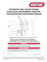
LED status
lock position status
The status normally displays for 10secs
after lock movement / button press.
LED STATUS INDICATORS
RED GREEN LOCK STATUS
FLASHING RAPIDLY LOCKING
ON LOCKED
FLASHING RAPIDLY UNLOCKING
ON UNLOCKED
ON ON ERROR
FLASHING SLOWLY FLASHING SLOWLY LOW BATTERY
FLASHING
ALTERNATIVELY
FLASHING
ALTERNATIVELY
NO LINK WITH
BASESTATION
troubleshooting
problem cause remedy
door not moving communication failure switch off power to opener, the switch back on after 30
secs (If a battery backup is installed press & hold STOP/
SET button on the opener until power ceases). Press the
lock/ unlock button on the lock to test operation.
Press the (i) button on the lock & refer to the LED status
table above.
main light flashes 3 times
on the opener
low battery indicator replace the batteries as per instructions below.
door not moving and no
lights on lock
limited battery power press the (i) button on the lock to see if there is power
in the battery.
no lights - change battery
lights - check LED status table.
main light flashing 5 times
on the opener
lock is not unlocked and preventing
the door moving
check lock, test by pressing emergency release button
on the lock and then test door operation.
lock is not unlocking
and preventing doors
movement
lock jammed
door wheel is pushing on the lock
barrel.
remove the lock drive unit from the locking mechanism
and test the manual operation of the bolt by engageing
and disengaging the lock manually.
check the lock barrel is not catching on the track.
red and green lights both
on solid on the lock.
error with lock press the unlock button on the lock to test operation.
switch off power to opener, then switch back on after 30
secs (If a battery backup is installed press & hold STOP/
SET button on the opener until power ceases). Press the
lock/ unlock button on the lock to test operation. If it
does not move contact your installer.
red and green lights on
one lock flashing slowly
low battery change battery, then test operation of lock by pressing
the lock / unlock button.
red and green lights
flashing alternatively
no link to opener press the unlock button on the lock with flashing lights
to disengage the bolt. Call your installer for assitance.

7
Auto-Lock Installation Instructions
Radiation Exposure Statement
This device complies with Part 15 of the FCC Rules / Innovation, Science and Economic Development (ISED) Canada’s licence-
exempt RSS(s). Operation is subject to the following two conditions:
(1) This device may not cause harmful interference, and
(2) This device must accept any interference received, including interference that may cause undesired operation.
This equipment complies with FCC and ISED radiation exposure limits set forth for an uncontrolled environment. This
equipment should be installed and operated with minimum distance 20cm between the radiator and the body.
Déclaration d’exposition aux radiations:
L’émetteur/récepteur exempt de licence contenu dans le présent appareil est conforme aux CNR d’Innovation, Sciences et
Développement économique Canada applicables aux appareils radio exempts de licence. L’exploitation est autorisée aux
deux conditions suivantes :
(1) L’appareil ne doit pas produire de brouillage;
(2) L’appareil doit accepter tout brouillage radioélectrique subi, même si le brouillage est susceptible d’en compromettre le
fonctionnement.
Cet équipement est conforme aux limites d’exposition aux rayonnements FCC et ISED établies pour un environnement non
contrôlé. Cet équipement doit être installé et utilisé avec un minimum de 20 cm de distance entre la source de rayonnement
et votre corps.
FCC Caution: Any changes or modifications not expressly approved by the party responsible for compliance could void the
user’s authority to operate this equipment.
FCC Class B Information
This equipment has been tested and found to comply with the limits for a Class B digital device, pursuant to part 15 of the
FCC Rules. These limits are designed to provide reasonable protection against harmful interference in a residential installation.
This equipment generates, uses and can radiate radio frequency energy and, if not installed and used in accordance with the
instructions, may cause harmful interference
to radio communications. However, there is no guarantee that interference will not occur in a particular
If this equipment does cause harmful interference to radio or television reception, which can be determined by turning the
equipment off and on, the user is encouraged to try to correct the interference by one or more of the following measures:
• Reorient or relocate the receiving antenna.
• Increase the separation between the equipment and receiver.
• Connect the equipment into an outlet on a circuit different from that to which the receiver is connected.
• Consult the dealer or an experienced radio/TV technician for help.
CAN ICES-003 (B) / NMB-003

Automatic Technology America
VIneyard Centre II, 1452 Hughes Road, Grapevine, Texas 76051, United States of America
P: +1 817 873 5076 W: www.automatictechnology.com
-
 1
1
-
 2
2
-
 3
3
-
 4
4
-
 5
5
-
 6
6
-
 7
7
-
 8
8


Automatic Technology Garage Door Lock Manuel utilisateur
- Taper
- Manuel utilisateur
dans d''autres langues
Autres documents
-
Chamberlain RJO70 Manuel utilisateur
-
Chamberlain 211X Manuel utilisateur
-
Quantum 3314 Owner Installation And User Manual
-
Craftsman 139.18452D Le manuel du propriétaire
-
-
-
Genie 1028 Operation & Maintenance Manual
-
 Genie Company 6072H-BV Le manuel du propriétaire
-
