
Designed for operating in USA & Canada only.
When this product is used in areas other than the USA & Canada,
we cannot guarantee the product quality and performance.
SAFETY INSTRUCTIONS AND INSTRUCTION MANUAL
WARNING
IMPROPER OR UNSAFE use of this power tool can result in death or serious bodily injury!
This manual contains important information about product safety. Please read and understand
this manual before operating the power tool. Please keep this manual available for other users
and owners before they use the power tool. This manual should be stored in safe place.
INSTRUCTIONS DE SECURITE ET MODE D’EMPLOI
AVERTISSEMENT
Une utilisation INCORRECTE OU DANGEREUSE de cet outil motorisé peut entraîner la mort
ou de sérieuses blessures corporelles!
Ce mode d’emploi contient d’importantes informations à propos de la sécurité de ce produit.
Prière de lire et de comprendre ce mode d’emploi AVANT d’utiliser l’outil motorisé. Garder ce
mode d’emploi à la disponibilité des autres utilisateurs et propriétaires avant qu’ils utilisent l’outil
motorisé. Ce mode d’emploi doit être conservé dans un endroit sûr.
INSTRUCCIONES DE SEGURIDAD Y MANUAL DE INSTRUCCIONES
ADVERTENCIA
¡La utilización INAPROPIADA O PELIGROSA de esta herramienta eléctrica puede resultar
en lesiones de gravedad o la muerte!
Este manual contiene información importante sobre la seguridad del producto. Lea y
comprenda este manual ANTES de utilizar la herramienta eléctrica. Guarde este manual para
que puedan leerlo otras personas antes de utilizar la herramienta eléctrica. Este manual debe
ser guardado en un lugar seguro.
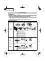
Model
Modèle
Modelo
DS 18DC
DV 18DC • DV 36DC
Cordless Driver Drill
Perceuse-visseuse sans fi l
Taladro atornillador inalámbrico
Cordless Hammer Drill
Perceuse à percussion sans fi l
Taladro de percusión inalámbrico
DS18DC DV18DC / DV36DC

IMPORTANT SAFETY INFORMATION
Read and understand all of the safety precautions, warnings and operating instructions in the Instruction Manual before
operating or maintaining this power tool.
Most accidents that result from power tool operation and maintenance are caused by the failure to observe basic safety
rules or precautions. An accident can often be avoided by recognizing a potentially hazardous situation before it occurs,
and by observing appropriate safety procedures.
Basic safety precautions are outlined in the “SAFETY” section of this Instruction Manual and in the sections which
contain the operation and maintenance instructions.
Hazards that must be avoided to prevent bodily injury or machine damage are identifi ed by WARNINGS on the power
tool and in this Instruction Manual.
NEVER use this power tool in a manner that has not been specifi cally recommended by metabo HPT.
MEANINGS OF SIGNAL WORDS
WARNING indicates a potentially hazardous situations which, if ignored, could result in death or serious injury.
CAUTION indicates a potentially hazardous situations which, if not avoided, may result in minor or moderate injury, or
may cause machine damage.
NOTE emphasizes essential information.
SAFETY
GENERAL POWER TOOL SAFETY WARNINGS
WARNING
Read all safety warnings, instructions, illustrations and specifi cations provided with this power tool.
Failure to follow all instructions listed below may result in electric shock, fi re and/or serious injury.
Save all warnings and instructions for future reference.
The term “power tool” in the warnings refers to your mains-operated (corded) power tool or battery-operated
(cordless) power tool.
1) Work area safety
a) Keep work area clean and well lit.
Cluttered or dark areas invite accidents.
b) Do not operate power tools in explosive
atmospheres, such as in the presence of
fl ammable liquids, gases or dust.
Power tools create sparks which may ignite the
dust or fumes.
c) Keep children and bystanders away while
operating a power tool.
Distractions can cause you to lose control.
2) Electrical safety
a) Power tool plugs must match the outlet.
Never modify the plug in any way.
Do not use any adapter plugs with earthed
(grounded) power tools.
Unmodifi ed plugs and matching outlets will reduce
risk of electric shock.
b) Avoid body contact with earthed or grounded
surfaces, such as pipes, radiators, ranges
and refrigerators.
There is an increased risk of electric shock if your
body is earthed or grounded.
c) Do not expose power tools to rain or wet
conditions.
Water entering a power tool will increase the risk
of electric shock.
d) Do not abuse the cord. Never use the cord
for carrying, pulling or unplugging the power
tool.
Keep cord away from heat, oil, sharp edges or
moving parts.
Damaged or entangled cords increase the risk of
electric shock.
e) When operating a power tool outdoors, use
an extension cord suitable for outdoor use.
Use of a cord suitable for outdoor use reduces the
risk of electric shock.
f) If operating a power tool in a damp location
is unavoidable, use a residual current device
(RCD) protected supply.
Use of an RCD reduces the risk of electric shock.
2
English

3) Personal safety
a) Stay alert, watch what you are doing and use
common sense when operating a power tool.
Do not use a power tool while you are tired
or under the infl uence of drugs, alcohol or
medication.
A moment of inattention while operating power
tools may result in serious personal injury.
b) Use personal protective equipment. Always
wear eye protection.
Protective equipment such as a dust mask, non-
skid safety shoes, hard hat, or hearing protection
used for appropriate conditions will reduce
personal injuries.
c) Prevent unintentional starting. Ensure the
switch is in the off -position before connecting
to power source and/or battery pack, picking
up or carrying the tool.
Carrying power tools with your fi nger on the switch
or energising power tools that have the switch on
invites accidents.
d) Remove any adjusting key or wrench before
turning the power tool on.
A wrench or a key left attached to a rotating part of
the power tool may result in personal injury.
e) Do not overreach. Keep proper footing and
balance at all times.
This enables better control of the power tool in
unexpected situations.
f) Dress properly. Do not wear loose clothing or
jewellery. Keep your hair and clothing away
from moving parts.
Loose clothes, jewellery or long hair can be caught
in moving parts.
g) If devices are provided for the connection
of dust extraction and collection facilities,
ensure these are connected and properly
used.
Use of dust collection can reduce dust-related
hazards.
h) Do not let familiarity gained from frequent use
of tools allow you to become complacent and
ignore tool safety principles.
A careless action can cause severe injury within a
fraction of a second.
4) Power tool use and care
a) Do not force the power tool. Use the correct
power tool for your application.
The correct power tool will do the job better and
safer at the rate for which it was designed.
b) Do not use the power tool if the switch does
not turn it on and off .
Any power tool that cannot be controlled with the
switch is dangerous and must be repaired.
c) Disconnect the plug from the power source
and/or remove the battery pack, if detachable,
from the power tool before making any
adjustments, changing accessories, or
storing power tools.
Such preventive safety measures reduce the risk
of starting the power tool accidentally.
d) Store idle power tools out of the reach of
children and do not allow persons unfamiliar
with the power tool or these instructions to
operate the power tool.
Power tools are dangerous in the hands of
untrained users.
e) Maintain power tools and accessories. Check
for misalignment or binding of moving parts,
breakage of parts and any other condition
that may aff ect the power toolʼs operation.
If damaged, have the power tool repaired
before use.
Many accidents are caused by poorly maintained
power tools.
f) Keep cutting tools sharp and clean.
Properly maintained cutting tools with sharp
cutting edges are less likely to bind and are easier
to control.
g) Use the power tool, accessories and tool bits
etc. in accordance with these instructions,
taking into account the working conditions
and the work to be performed.
Use of the power tool for operations diff erent
from those intended could result in a hazardous
situation.
h) Keep handles and grasping surfaces dry,
clean and free from oil and grease.
Slippery handles and grasping surfaces do not
allow for safe handling and control of the tool in
unexpected situations.
5) Battery tool use and care
a) Recharge only with the charger specifi ed by
the manufacturer.
A charger that is suitable for one type of battery
pack may create a risk of fi re when used with
another battery pack.
b) Use power tools only with specifi cally
designated battery packs.
Use of any other battery packs may create a risk of
injury and fi re.
c) When battery pack is not in use, keep it away
from other metal objects, like paper clips,
coins, keys, nails, screws or other small metal
objects, that can make a connection from one
terminal to another.
Shorting the battery terminals together may cause
burns or a fi re.
3
English

Cutting accessory or fasteners contacting a “live” wire
may make exposed metal parts of the power tool “live”
and could give the operator an electric shock.
Safety instructions when using long drill bits
5. Never operate at higher speed than the maximum
speed rating of the drill bit.
At higher speeds, the bit is likely to bend if allowed
to rotate freely without contacting the workpiece,
resulting in personal injury.
6. Always start drilling at low speed and with the bit
tip in contact with the workpiece.
At higher speeds, the bit is likely to bend if allowed
to rotate freely without contacting the workpiece,
resulting in personal injury.
7. Apply pressure only in direct line with the bit and
do not apply excessive pressure.
Bits can bend causing breakage or loss of control,
resulting in personal injury.
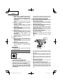
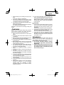
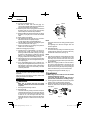
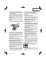
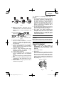
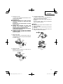
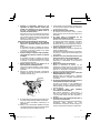
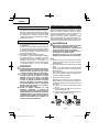
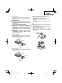
8. Make sure to securely hold the tool during
operation.
Failure to do so can result in accidents or injuries.
(Fig. 1)
Fig. 1
9. Never place hands or other body parts near the drill
bit or chuck during operation. Hold the drill by its
handle only.
10. Because the cordless tool operates by battery power,
be aware of the fact that it can begin to operate at any
time.
11. When working at elevated locations, clear the area
of all other people and be aware of conditions below
you.
12. Never touch moving parts.
Never place your hands, fi ngers or other body parts
near the tool’s moving parts.
13. Never operate without all guards in place.
Never operate this tool without all guards or safety
features in place and in proper working order. If
maintenance or servicing requires the removal of a
guard or safety feature, be sure to replace the guard
or safety feature before resuming operation of the
tool.
d) Under abusive conditions, liquid may be
ejected from the battery; avoid contact. If
contact accidentally occurs, fl ush with water.
If liquid contacts eyes, additionally seek
medical help.
Liquid ejected from the battery may cause irritation
or burns.
e) Do not use a battery pack or tool that is
damaged or modifi ed.
Damaged or modifi ed batteries may exhibit
unpredictable behaviour resulting in fi re, explosion
or risk of injury.
f) Do not expose a battery pack or tool to fi re or
excessive temperature.
Exposure to fi re or temperature above 265 °F may
cause explosion.
g) Follow all charging instructions and do
not charge the battery pack or tool outside
the temperature range specifi ed in the
instructions.
Charging improperly or at temperatures outside
the specifi ed range may damage the battery and
increase the risk of fi re.
6) Service
a) Have your power tool serviced by a
qualifi ed repair person using only identical
replacement parts.
This will ensure that the safety of the power tool is
maintained.
b) Never service damaged battery packs.
Service of battery packs should only be performed
by the manufacturer or authorized service
providers.
– WARNING –
To reduce the risk of injury, user must read
instruction manual.
SPECIFIC SAFETY RULES AND SYMBOLS
1. Wear ear protectors with impact drilling.
Exposure to noise can cause hearing
loss.
2. Use auxiliary handle(s).
Loss of control can cause personal injury.
3. Brace the tool properly before use.
This tool produces a high output torque and without
properly bracing the tool during operation, loss of
control may occur resulting in personal injury.
4. Hold the power tool by insulated gripping
surfaces, when performing an operation where
the cutting accessory or fasteners may contact
hidden wiring.
4
English

14. Use right tool.
Don’t force small tool or attachment to do the job of a
heavy-duty tool.
Don’t use tool for purpose not intended —for
example— don’t use circular saw for cutting tree
limbs or logs.
15. Never use a power tool for applications other
than those specifi ed.
Never use a power tool for applications other than
those specifi ed in the instruction manual.
16. Handle tool correctly.
Operate the tool according to the instructions provided
herein. Do not drop or throw the tool. Never allow the
tool to be operated by children, individuals unfamiliar
with its operation or unauthorized personnel.
17. Keep all screws, bolts and covers tightly in place.
Keep all screws, bolts, and plates tightly mounted.
Check their condition periodically.
18. Do not use power tools if the plastic housing or
handle is cracked.
Cracks in the tool’s housing or handle can lead to
electric shock. Such tools should not be used until
repaired.
19. Accessories must be securely mounted to the
tool.
Prevent potential injuries to yourself or others.
Accessories which have been mounted to the tool
should be secure and tight.
20. Never use a tool which is defective or operating
abnormally.
If the tool appears to be operating unusually, making
strange noises, or otherwise appears defective, stop
using it immediately and arrange for repairs by a
metabo HPT authorized service center.
21. Carefully handle power tools.
Should a power tool be dropped or struck against
hard materials inadvertently, it may be deformed,
cracked, or damaged.
22. Do not wipe plastic parts with solvent.
Solvents such as gasoline, thinner benzine, carbon
tetrachloride, and alcohol may damage and crack
plastic parts. Do not wipe them with such solvents.
Wipe plastic parts with a soft cloth lightly dampened
with soapy water and dry thoroughly.
23. Always wear eye protection that meets the
requirement of the latest revision of ANSI
Standard Z87.1.
24. Do not touch metal parts of the tool body, bits, drills, or
swarf immediately after use, as these will be hot.
25. Do not use the product if the tool or the battery
terminals (battery mount) are deformed.
Installing the battery could cause a short circuit that
could result in smoke emission or ignition.
26. Keep the tool’s terminals (battery mount) free of swarf
and dust.
○
Prior to use, make sure that swarf and dust have not
collected in the area of the terminals.
○
During use, try to avoid swarf or dust on the tool from
falling on the battery.
○
When suspending operation or after use, do not leave
the tool in an area where it may be exposed to falling
swarf or dust.
Doing so could cause a short circuit that could result
in smoke emission or ignition.
27. Always use the tool and battery at temperatures
between 23°F (-5°C) and 104°F (40°C).
28. Defi nitions for symbols used on this tool
V ............ volts
—
---
......... direct current
no .......... no load speed
---/min .... revolutions or reciprocation per minute
IMPORTANT SAFETY INSTRUCTIONS
FOR BATTERY CHARGER
WARNING
Death or serious bodily injury could result from
improper or unsafe use of battery chargers.
To avoid these risks, follow these basic safety
instructions:
READ ALL INSTRUCTIONS
1. This manual contains important safety and operating
instructions for battery charger Model UC18YSL3.
2. Before using battery charger, read all instructions
and cautionary markings on (1) battery charger, (2)
battery, and (3) product using battery.
3. To reduce risk of injury, charge metabo HPT
rechargeable battery types BSL18 series and multi
volt series. Other type of batteries may burst causing
personal injury and damage.
4. Use of an attachment not recommended or sold by
the battery charger manufacturer may result in a risk
of fi re, electric shock, or injury to persons.
5. To reduce risk of damage to electric plug and cord,
pull by plug when disconnecting battery charger.
6. Make sure cord is located so that it will not be stepped
on, tripped over, or otherwise subjected to damage or
stress.
7. An extension cord should not be used unless
absolutely necessary. Use of improper extension
cord could result in a risk of fi re and electric shock.
If extension cord must be used make sure:
a. That blades of extension cord are the same
number, size, and shape as those of plug on
battery charger:
b. That extension cord is properly wired and in good
electrical condition; and
c. That wire size is large enough for AC ampere
rating of battery charger as specifi ed in Table 1.
5
English

* If the input rating of a battery charger is given in watts
rather than in amperes, the corresponding ampere
rating is to be determined by dividing the wattage
rating by the voltage rating–for example:
1,250 watts = 10 amperes
125 volts
8. Do not operate battery charger with damaged cord or
plug-replace them immediately.
9. Do not operate battery charger if it has received a
sharp blow, been dropped, or otherwise damaged in
any way; take it to a qualifi ed serviceman.
10. Do not disassemble battery charger; take it to a
qualifi ed serviceman when service or repair is
required. Incorrect reassembly may result in a risk of
electric shock or fi re.
11. To reduce risk of electric shock, unplug charger from
receptacle before attempting any maintenance or
cleaning. Removing the battery will not reduce this
risk.
IMPORTANT SAFETY INSTRUCTIONS
FOR USE OF THE BATTERY AND
BATTERY CHARGER
You must charge the battery before you can use the power
tool. Before using the model UC18YSL3 battery charger,
be sure to read all instructions and cautionary statements
on it, the battery and in this manual.
CAUTION
USE ONLY metabo HPT BATTERIES. OTHER
MODELS OF BATTERIES MAY BURST AND
CAUSE INJURY!
Follow these instructions to avoid the risk of injury:
WARNING:
Improper use of the battery
or battery charger can lead to
serious injury. To avoid these
injuries:
1. NEVER disassemble the battery.
2. NEVER incinerate the battery, even if it is damaged or
is completely worn out. The battery can explode in a
fi re.
3. NEVER short-circuit the battery.
4. NEVER insert any objects into the battery charger’s
air vents. Electric shock or damage to the battery
charger may result.
5. NEVER charge outdoors. Keep the battery away
from direct sunlight and use only where there is low
humidity and good ventilation.
6. NEVER charge when the temperature is below 32°F
(0°C) or above 104°F (40°C).
7. NEVER connect two battery chargers together.
8. NEVER insert foreign objects into the hole for the
battery or the battery charger.
9. NEVER use a booster transformer when charging.
10. NEVER use DC power to charge.
11. NEVER store the battery or battery charger in places
where the temperature may reach or exceed 104°F
(40°C) such as inside metal box or car.
12. NEVER expose the battery or battery charger to rain
or wet conditions.
13. ALWAYS operate charger on standard household
electrical power (120 volts). Using the charger on any
other voltage may overheat and damage the charger.
14. ALWAYS wait at least 15 minutes between charges to
avoid overheating the charger.
15. ALWAYS disconnect the power cord from its
receptacle when the charger is not in use.
CAUTION ON LITHIUM-ION BATTERY
To extend the lifetime, the lithium-ion battery equips with
the protection function to stop the output.
In the cases of 1 to 3 described below, when using this
product, even if you are pulling the switch, the motor may
stop. This is not the trouble but the result of protection
function.
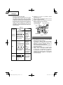
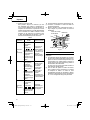
Table 1
RECOMMENDED MINIMUM AWG SIZE FOR
EXTENSION CORDS FOR BATTERY CHARGERS
AC Input Rating Amperes* AWG Size of Cord
Equal to or
greater than but less
than
Length of Cord, Feet (Meter)
25 (7.5) 50 (15) 100 (30) 150 (45)
0 2 18 18 18 16
2 3 18 18 16 14
3 4 18 18 16 14
6
English

1. When the battery power remaining runs out, the motor
stops.
In such case, charge it up immediately.
2. If the tool is overloaded, the motor may stop. In this
case, release the switch of tool and eliminate causes
of overloading. After that, you can use it again.
3. If the battery is overheated under overload work, the
battery power may stop.
In this case, stop using the battery and let the battery
cool. After that, you can use it again.
Furthermore, please heed the following warning and
caution.
WARNING
In order to prevent any battery leakage, heat generation,
smoke emission, explosion and ignition beforehand,
please be sure to heed the following precautions.
1. Make sure that swarf and dust do not collect on the
battery.
○
During work make sure that swarf and dust do not fall
on the battery.
○
Make sure that any swarf and dust falling on the power
tool during work do not collect on the battery.
○
Do not store an unused battery in a location exposed
to swarf and dust.
○
Before storing a battery, remove any swarf and dust
that may adhere to it and do not store it together with
metal parts (screws, nails, etc.).
2. Do not pierce battery with a sharp object such as a
nail, strike with a hammer, step on, throw or subject
the battery to severe physical shock.
3. Do not use an apparently damaged or deformed
battery.
4. Do not use the battery for a purpose other than those
specifi ed.
5. If the battery charging fails to complete even when a
specifi ed recharging time has elapsed, immediately
stop further recharging.
6. Do not put or subject the battery to high temperatures
or high pressure such as into a microwave oven,
dryer, or high pressure container.
7. Keep away from fi re immediately when leakage or foul
odor are detected.
8. Do not use in a location where strong static electricity
generates.
9. If there is battery leakage, foul odor, heat generated,
discolored or deformed, or in any way appears
abnormal during use, recharging or storage,
immediately remove it from the equipment or battery
charger, and stop use.
10. Do not immerse the battery or allow any fl uids to fl ow
inside. Conductive liquid ingress, such as water, can
cause damage resulting in fi re or explosion. Store your
battery in a cool, dry place, away from combustible
and fl ammable items. Corrosive gas atmospheres
must be avoided.
CAUTION
1. If liquid leaking from the battery gets into your eyes,
do not rub your eyes and wash them well with fresh
clean water such as tap water and contact a doctor
immediately.
If left untreated, the liquid may cause eye-problems.
2. If liquid leaks onto your skin or clothes, wash well with
clean water such as tap water immediately.
There is a possibility that this can cause skin irritation.
3. If you fi nd rust, foul odor, overheating, discolor,
deformation, and/or other irregularities when using
the battery for the fi rst time, do not use and return it to
your supplier or vendor.
WARNING
If an electrically conductive foreign object enters the
terminals of the lithium ion battery, a short-circuit may
occur resulting in the risk of fi re. Please observe the
following matters when storing the battery.
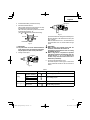
○
Do not place electrically conductive cuttings,
nails, steel wire, copper wire or other wire in the
storage case.
○
Either install the battery in the power tool or store
by securely pressing into the battery cover until
the ventilation holes are concealed to prevent
short-circuits (See Fig. 4).
7
English

SAVE THESE INSTRUCTIONS
AND
MAKE THEM AVAILABLE TO OTHER USERS
AND
OWNERS OF THIS TOOL!
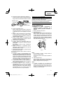
REGARDING LITHIUM-ION BATTERY
TRANSPORTATION
When transporting a lithium-ion battery, please observe
the following precautions.
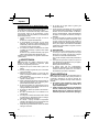
WARNING
Notify the transporting company that a package
contains a lithium-ion battery, inform the company
of its power output and follow the instructions of the
transportation company when arranging transport.
●
Lithium-ion batteries that exceed a power output
of 100 Wh are considered to be in the freight
classifi cation of Dangerous Goods and will
require special application procedures.
●
For transportation abroad, you must comply with
international law and the rules and regulations of
the destination country.
Wh
Power Output
2 to 3 digit number
Fig. 2
8
English

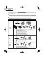
FUNCTIONAL DESCRIPTION
NOTE
The information contained in this Instruction Manual is designed to assist you in the safe operation and maintenance
of the power tool.
NEVER operate, or attempt any maintenance on the tool unless you have fi rst read and understood all safety
instructions contained in this manual.
Some illustrations in this Instruction Manual may show details or attachments that diff er from those on your own
power tool.
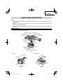
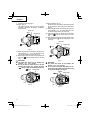
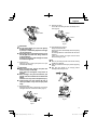
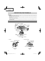
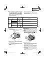
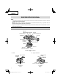
NAME OF PARTS
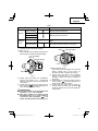
1. Cordless Driver Drill / Cordless Hammer Drill
Housing
Motor
Gear case
Clutch dial
Keyless chuck
Shift knob
Side handle
Push button
Ventilation holes
Trigger switch
Battery
Ventilation holes
Hook
Handle
Name plate
LED Light
<DS18DC / DV18DC / DV36DC>
Fig. 3
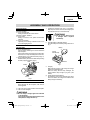
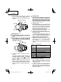
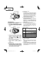
2. Battery 3. Battery Charger
Battery
Ventilation holes
Terminals
Battery cover
Latch
Ventilation
holes
Body
Cord
Nameplate
Charge
indicator lamp
Guide rail
<BSL36A18X> <UC18YSL3>
Fig. 4 Fig. 5
9
English

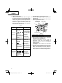
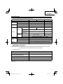
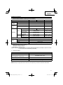
SPECIFICATIONS
1. Cordless Driver Drill / Cordless Hammer Drill
Model DS18DC DV18DC DV36DC
Motor DC Brushless motor
No-load
speed
Low 0–500 /min 0–550 /min
High 0–2,000 /min 0–2,200 /min
No-load
impact rate
Low 0–7,500 /min 0–8,250 /min
High 0–30,000 /min 0–33,000 /min
Capacity
Drilling
Brick *1 ————— 3/4 in. (20 mm) 7/8 in. (22 mm)
Wood *1
(Soft Wood) 4 in. (102 mm) 4-5/8 in. (118 mm)
Metal *1
(Mild Steel) 5/8 in. (16 mm) 3/4 in. (20 mm)
Screw Driver Wood screw 7/16 in. × 4 in.
(12 mm × 100 mm) 5/8 in. × 4 in.
(16 mm × 100 mm)
Small screw 1/4 in. (6 mm)
Drill chuck capacity Maximum gripping diameter 1/2 in. (13 mm)
Battery
Model BSL36A18X
Type Li-ion battery
Voltage DC 36 V / 18 V
Weight 6.2 lbs. (2.8 kg) (BSL36A18X and side handle attached)
*1 Brick: Depth 1-1/4 in. (30 mm)
Wood: Thickness 1-1/2 in. (38 mm)
Metal: Thickness 1/16 in. (1.6 mm)
DV36DC only: Existing batteries (BSL3660/3626/3620, BSL18xx and BSL14xx series, etc.) cannot be used with this
tool. Use multi volt type battery.
2. Battery Charger
Model UC18YSL3
Input power source Single phase: AC 120 V 60 Hz
Charging time
(At a temperature of 68°F (20°C)) BSL36A18X : Approx. 32 min
Charging voltage DC 14.4–18 V
Charging current DC 8.0 A
Weight 1.3 lbs. (0.6 kg)
NOTE: The charging time may vary according to temperature and power source voltage.
10
English

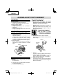
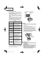
ASSEMBLY AND OPERATION
1. Connect the charger’s power cord to a receptacle.
When the power cord is connected, the charger’s pilot
lamp will blink in red. (At 1-second intervals)
WARNING
Do not use the electrical cord
if damaged. Have it repaired
immediately.
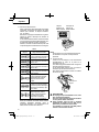
2. Insert the battery to the battery charger.
Insert the battery into the battery charger as shown in
Fig. 7.
Charge
indicator lamp
Guide rail
Battery
Fig. 7
3. Charging
When inserting a battery in the charger, the charge
indicator lamp will blink in blue.
When the battery becomes fully recharged, the
charge indicator lamp will light up in green. (See
Table 2)
(1) Charge indicator lamp indication
The indications of the charge indicator lamp will be
as shown in Table 2, according to the condition of the
battery charger or the battery.
APPLICATIONS
<DV18DC / DV36DC>
○
Use as a hammer drill
Drilling of soft bricks and concrete blocks.
<DS18DC / DV18DC / DV36DC>
○
Use as a drill
Drilling of soft steel, wood, plastic and aluminum
materials.
○
Use as a screwdriver
Tightening and loosening of machine screws, wood
screws and tapping screws.
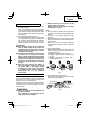
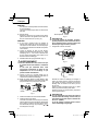
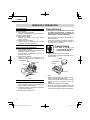
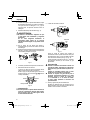
REMOVAL AND INSTALLATION METHOD
OF BATTERY
○
How to install the battery.
Align the battery with the groove in tool handle and
slip it into place.
Always insert it all the way until it locks in place with a
little click, If not, it may accidentally fall out of the tool,
causing injury to you or someone around you (Fig. 6).
○
How to remove the battery.
Withdraw battery from the tool handle while pressing
the latch (2 pcs) of the battery (Fig. 6).
Battery
Push
Pull out Insert
Handle
Latch
Fig. 6
CHARGING METHOD
NOTE
Before plugging into the receptacle, make sure the
following points.
○
The power source voltage is stated on the nameplate.
○
The cord is not damaged.
WARNING
Do not charge at voltage higher than indicated
on the nameplate.
If charged at voltage higher than indicated on the
nameplate, the charger will burn up.
11
English

(2) Regarding the temperature of the rechargeable
battery.
The temperatures for rechargeable batteries are
as shown in the Table 3, and batteries that have
become hot should be cooled for a while before being
recharged.
Table 3
Rechargeable
batteries Temperatures at which the battery
can be recharged
BSL36A18X 32°F–122°F
(0°C–50°C)
(3) Regarding recharging time (At 68°F (20°C))
Table 4 Charging time
Charger
Battery UC18YSL3
BSL36A18X Approx. 32 min
NOTE
The recharging time may vary according to the
ambient temperature.
4. Disconnect battery charger from the receptacle.
CAUTION
Do not pull the plug out of the receptacle by
pulling on the cord.
Make sure to grasp the plug when removing from
receptacle to avoid damaging cord.
5. Remove the battery from the battery charger.
Supporting the battery charger with hand, pull out the
battery from the battery charger.
NOTE
Be sure to pull out the battery from the battery charger
after use, and then keep it.
Regarding electric discharge in case of new
batteries, etc.
As the internal chemical substance of new batteries
and batteries that have not been used for an extended
period is not activated, the electric discharge might
be low when using them the fi rst and second time.
This is a temporary phenomenon, and normal time
required for recharging will be restored by recharging
the batteries 2–3 times.
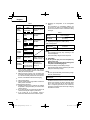
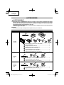
Table 2
Charger
status Status of indicator
lamp Indication meaning
Before
charging
ON/OFF at 0.5 sec.
intervals (RED) Plugged into power
source *1
While
charging
Lights for 0.5 sec.
at intervals of 1 sec.
(BLUE) Charged at less
than 50%
Lights for 1 sec. at
intervals of 0.5 sec.
(BLUE) Charged at less
than 80%
Lights continuously
(BLUE) Charged at more
than 80%
Charging
complete
Lights continuously
(GREEN)
(Continuous buzzer
sound: about 6 sec.)
Overheat
standby
ON/OFF at 0.3 sec.
intervals (RED) Battery overheated.
Unable to charge. *2
Charging
impossible
ON/OFF at 0.1 sec.
intervals (PURPLE)
(Intermittent buzzer
sound; about 2 sec.)
Malfunction in
the battery or the
charger *3
*1 If the red lamp continues to blink even after the
charger has been attached, check to confi rm that the
battery has been fully inserted.
*2 Although charging will start once the battery has
cooled down even when left in situ, the best practice
is to remove the battery and allow it to cool down in a
shaded, well-ventilated location before charging.
*3
○ Fully insert the battery.
○ Check to confi rm that no foreign matter is stuck to the
battery mount or terminals.
<If charging takes a long time>
○ Charging will take longer at extremely low ambient
temperatures. Charge the battery in a warm location
(such as indoors).
○ Do not block the air vent. Otherwise the interior will
overheat, reducing the charger’s performance.
○ If the cooling fan is not operating, contact a
metabo HPT Authorized Service Center for repairs.
12
English

○
When the product is not being used, cover the
USB port with the rubber cover.
Buildup of dust etc. in the USB port can cause
smoke emission or ignition.
NOTE
○
The time required for charging will be longer when
a USB device and battery are being simultaneously
charged.
○
There may be an occasional pause during USB
recharging.
○
When a USB device is not being charged, turn the
USB power switch OFF and remove the USB device
from the charger.
Failure to do so may not only reduce the battery life
of a USB device, but may also result in unexpected
accidents.
(1) Select a charging method
Depending on the charge method selected, either the
battery is inserted into the charger or the power cord
is plugged into an outlet.
○
Charging a USB device by battery (Fig. 8-a)
○
Charging a USB device from a electrical outlet
(Fig. 8-b)
○
Charging a USB device and battery from a
electrical outlet (Fig. 8-c)
abc
Fig. 8
(2) Turn the USB power switch ON (Fig. 9)
When you turn the USB power switch ON, the USB
power indicator lamp will light up.
USB power
switch
USB power
indicator lamp
Rubber cover
USB port
USB cable
Fig. 9
How to make the batteries perform longer
(1) Recharge the batteries before they become
completely exhausted.
When you feel that the power of the tool becomes
weaker, stop using the tool and recharge its battery.
If you continue to use the tool and exhaust the electric
current, the battery may be damaged and its life will
become shorter.
(2) Avoid recharging at high temperatures.
A rechargeable battery will be hot immediately after
use. If such a battery is recharged immediately after
use, its internal chemical substance will deteriorate,
and the battery life will be shortened. Leave the
battery and recharge it after it has cooled for a while.
CAUTION
●
When the battery charger has been continuosly
used, the battery charger will be heated, thus
constituting the cause of the failures. Once the
charging has been completed, give 15 minutes
rest until the next charging.
●
If the battery is charged while it is heated because
it has been left for a long time in a location
subject to direct sunlight or because the battery
has just been used, the charge indicator lamp of
UC18YSL3 charger lights for 0.3 seconds, does
not light for 0.3 seconds (off for 0.3 seconds). In
such a case, fi rst let the battery cool, then start
charging.
●
When the charge indicator lamp fl ickers (at
0.2–second intervals), check for and take out
any foreign objects in the charger’s battery
installation hole. If there are no foreign objects,
it is probable that the battery or charger is
malfunctioning. Take it to your authorized
Service Center.
HOW TO RECHARGE USB DEVICE
When an unexpected problem occurs, the data in a USB
device connected to this product may be corrupted or lost.
Always make sure to back up any data contained in the
USB device prior to use with this product.
Please be aware that our company accepts absolutely no
responsibility for any data stored in a USB device that is
corrupted or lost, nor for any damage that may occur to a
connected device.
WARNING
○
Prior to use, check the connecting USB cable for
any defect or damage.
Using a defective or damaged USB cable can
cause smoke emission or ignition.
13
English

(3) Connect the USB cable. (Fig. 9)
Pull back the rubber cover and fi rmly plug in a
commercially available USB cable (appropriate to the
device being charged) into the USB port.
○
When the power cord is not plugged into an outlet and
the battery runs out of power, power output will stop
and the USB power indicator lamp will shut off .
○
When the USB power indicator lamp goes out, change
the battery or plug the power cord into an electrical
outlet.
(4) When charging is completed
○
The USB power indicator lamp will not go out when a
USB device has been completely charged.
To verify charge status, check the USB device.
○
Turn the USB power switch OFF and unplug the power
cord from the electrical outlet. (Fig. 9)
○
Remove the battery from the charger and place the
rubber cover over the USB port.
<USB device charging stops midway>
○
Charging stops for approximately fi ve seconds to
allow the power supply to be detected under the
following conditions: if the battery charger power plug
is plugged in while charging a USB device from the
battery, or if a rechargeable battery is inserted while
charging a USB device from the battery charger.
○
USB charging stops for fi ve seconds so that checking
can be performed once the rechargeable battery has
been fully charged.
○
If the rechargeable battery level is extremely low,
charging the rechargeable battery takes priority, and
USB charging is temporarily stopped. USB charging
automatically resumes once the battery level has
reached a preset level.
BEFORE USE
Check the work area to make sure that it is clear of debris
and clutter.
Clear the area of unnecessary personnel. Ensure that
lighting and ventilation is adequate.
OPERATION
WARNING
Make sure to securely hold the tool during
operation. Failure to do so can result in accidents
or injuries.
1. Mounting and dismounting of the bit.
(1) Mounting the bit.
Loosen the sleeve by turning it toward the left (in the
counterclockwise direction as viewed from the front)
to open the clip on the keyless chuck. After inserting
a driver bit, etc., into the keyless drill chuck, and
tighten the sleeve by turning it toward the right (in the
clockwise direction as viewed from the front). (See
Fig. 10).
Tighten
Loosen Sleeve
Fig. 10
NOTE
If the sleeve becomes loose during operation, tighten
it further.
The tightening force becomes stronger when the
sleeve is tightened.
(2) Dismounting the bit
Loosen the sleeve by turning it toward the left (in the
counterclockwise direction as viewed from the front),
and then take out the bit etc. (See Fig. 10)
NOTE
○
If the sleeve is tightened in a state where the clip of the
keyless chuck is opened to a maximum limit, a click
noise may occur. This is the noise that occurs when
the loosening of the keyless chuck is prevented and is
not a malfunction.
○
When it is no longer possible to loosen the sleeve,
use a vise or similar instrument to secure the bit. Set
the clutch mode between 1 and 11 and then turn the
sleeve to the loose side (left side) while operating the
clutch. It should be easy now to loosen the sleeve.
2. Installing/Removing the side handle. (Fig. 11)
WARNING
When using the tool, make sure the side handle
is attached and fi rmly secured.
If not fi rmly secured, the tool may jerk out of
position when overburdened, resulting in injury.
(1) Turn the grip of the side handle to loosen it and push it
in until it comes in contact with the clutch dial.
(2) Adjust the side handle to the angle that allows the
easiest use, then turn the side handle’s grip fi rmly to
lock it place.
Loosen
Clutch
dial
Side
handle
Tighten
Fig. 11
14
English

3. Confi rm that the battery is mounted correctly.
4. Check the rotational direction.
The bit rotates clockwise (viewed from the rear side)
by pushing the R-side of the push button.
The L-side of the push button is pushed to turn the bit
counterclockwise (See Fig. 12).
(The
and marks are provided on the body.)
Push button
Forward Reverse
Fig. 12
CAUTION
The push button can not be switched while the
power tool is turning. To switch the push button,
stop the power tool, then set the push button.
5. Change rotation speed.
Shift knob
Low speed
“1”
Fig. 13
Shift knob
High speed
“2”
Fig. 14
Operate the shift knob to change the rotational speed.
Move the shift knob in the direction of the arrow (See
Figs. 13 and 14).
When the shift knob is set to “1”, the drill rotates at a
low speed. When set to “2”, the drill rotates at a high
speed.
CAUTION
●
When changing the rotational speed with the
shift knob, confi rm that the switch is off .
Changing the speed while the motor is rotating
will damage the gears.
●
When a large force is required for operation
(operations indicated in the following chart) set
the shift knob to “1”. If “2” is set and the unit
is used, it may cause the motor to burn out or
malfunction prematurely.
6. The scope and suggestions for uses
The usable scope for various types of work based
on the mechanical structure of this unit is shown in
Table 5.
Table 5
Work Cap position Suggestions
Drilling
Brick
(DV18DC / DV36DC) Use for drilling purpose.
Wood
Use for drilling purpose.Steel
Aluminum
Screw tightening
Small screw 1 – 22 Use the bit and socket matching the screw diameter.
Wood screw 1 – Use after drilling a pilot hole.
15
English

7. Confi rm the clutch dial position.
<DS18DC> (Fig. 15)
The tightening torque of this unit can be adjusted
according to the clutch dial position, at which the
clutch dial is set.
Clutch dial
Triangle mark
Strong
Weak
mark
Fig. 15
(1) When using this unit as a screwdriver, line up the one
of the numbers “1, 4, 7 ... 22” on the clutch dial, or the
dot, with the triangle mark on the outer body.
(2) When using this unit as a drill, line up the clutch dial
drill mark “ ” with the triangle mark on the outer
body.
CAUTION
●
The clutch dial cannot be set between the
numbers “1, 4, 7 ... 22” or the dot.
●
Do not use with the clutch dial set at the line
between the number “22” and the drill mark
“”. Doing so may cause damage (See Fig. 16).
Line
Triangle mark
mark
Fig. 16
<DV18DC / DV36DC> (Fig. 17)
The three modes of screwdriver, drill and hammer drill
can be switched by the position of the clutch dial in
this unit.
(1) When using this unit as a screwdriver, line up the one
of the numbers “1, 4, 7 ... 22” on the clutch dial, or the
dot, with the triangle mark on the outer body.
(2) When using this unit as a drill, line up the clutch dial
drill mark “ ” with the triangle mark on the outer
body.
(3) When using this unit as a hammer drill, align the clutch
dial hammer mark “ ” with the triangle mark on the
outer body.
mark
Triangle mark
mark
Clutch dial
Weak
Strong
Fig. 17
CAUTION
●
The clutch dial cannot be set between the
number “1, 4, 7 ... 22” or the dot.
●
Do not use with the clutch dial number at “22”
and the line at the middle of the drill mark. Doing
so may cause damage. (See Fig. 18)
Line
mark Triangle mark
mark
Fig. 18
16
English

8. Rotation to Hammer changeover (DV18DC / DV36DC)
The “Rotation (Rotation only)” and “Hammer (Hammer
+ Rotation)” can be switched by aligning the drill mark
“” or the hammer mark “ ” with the triangle mark
on the outer body.
○
To make holes in the metal, wood or plastic, switch to
“Rotation (Rotation only)”.
○
To make holes in the bricks or concrete blocks, switch
to “Hammer (Hammer + Rotation)”.
CAUTION
Do not use the Cordless hammer drill in the
“Hammer” setting if the material can be bored
by rotation only. Such action will not only reduce
drill effi ciency, but may also damage the drill tip.
9. Tightening torque adjustment.
(1) Tightening torque
Tightening torque should correspond in its intensity to
the screw diameter. When too strong power is used,
the screw head may be broken or be injured.
Be sure to adjust the clutch dial position according to
the screw diameter.
Refer to Table 6 for the clutch dial position tightening
torques.
(2) Tightening torque indication (See Fig. 15, 17)
The tightening torque diff ers depending on the type of
screw and the material being tightened.
The unit indicates the tightening torque with the
numbers “1, 4, 7 ... 22” on the clutch dial, and a dot.
The tightening torque at position “1” is the weakest
and the torque is strongest at the highest number.
(3) Adjusting the tightening torque (See Fig. 15, 17)
Rotate the clutch dial and line up the numbers “1, 4, 7, ...
22” on the clutch dial, or the dot, with the triangle mark on
the outer body. Adjust the clutch dial in the weak or the
strong torque direction according to the torque you need.
Table 6 Tightening torque
Clutch dial
position Tightening torque
1 Approximately 13 in.-lbs. (15 kg-cm)
4 Approximately 21 in.-lbs. (29 kg-cm)
7 Approximately 30 in.-lbs. (34 kg-cm)
10 Approximately 38 in.-lbs. (44 kg-cm)
13 Approximately 46 in.-lbs. (53 kg-cm)
16 Approximately 54 in.-lbs. (63 kg-cm)
19 Approximately 63 in.-lbs. (72 kg-cm)
22 Approximately 71 in.-lbs. (82 kg-cm)
10. Switch operation
○
When the trigger switch is depressed, the tool rotates.
When the trigger is released, the tool stops.
When releasing the trigger of the switch, the brake will
be applied for immediate stopping.
○
The rotational speed of the drill can be controlled by
varying the amount that the trigger switch is pulled.
Speed is low when the trigger switch is pulled slightly
and increases as the trigger switch is pulled more.
CAUTION
●
The motor rotation may be locked to cease while
the unit is used as drill. While operating the
driver drill, take care not to lock the motor.
●
If the motor is locked, immediately turn the power
off . If the motor is locked for a while, the motor or
battery may be burnt.
11. For drilling into brick (DV18DC / DV36DC)
Excessive pressing force never increases drilling
speed. It will not only damage the drill tip or reduce
working effi ciency, but could also shorten the service
life of drill bit. Operate the hammer drill within 10-20 kg
pressing force while drilling into brick.
12. How to select rotational speed
CAUTION
●
The selection examples shown in Table 7 should
be considered as general standard. As diff erent
types of tightening screws and diff erent materials
to be tightened are used in actual works proper
adjustments are naturally necessary.
●
When using the driver drill/hammer drill with a
machine screw at 2 (high speed), a screw may
damage or a bit may loose due to the tightning
torque is too strong. Use the driver drill/hammer
drill at 1 (low speed) when using a machine
screw.
NOTE
The use of the battery in a cold condition (below
0 degree Centigrade) can sometimes result in the
weakened tightening torque and reduced amount of
work. This, however, is a temporary phenomenon,
and returns to normal when the battery warms up.
17
English

13. Remaining battery indicator
You can check the battery’s remaining capacity by
pressing the remaining battery indicator switch to light
the indicator lamp. (Fig. 19, Table 8)
The indicator will shut off approximately 3 seconds
after the remaining battery indicator switch is pressed.
It is best to use the remaining battery indicator as
a guide since there are slight diff erences such as
ambient temperature and the condition of the battery.
Also, the remaining battery indicator may vary from
those equipped to a tool or charger.
Table 8
State of lamp Battery Remaining Power
Lights ;
The battery remaining power is
over 75%.
Lights ;
The battery remaining power is
50%–75%.
Lights ;
The battery remaining power is
25%–50%.
Lights ;
The battery remaining power is
less than 25%.
Blinks ;
The battery remaining power
is nearly empty. Recharge the
battery soonest possible
Blinks ;
Output suspended due to high
temperature. Remove the
battery from the tool and allow it
to fully cool down.
Blinks ;
Output suspended due to failure
or malfunction. The problem
may be the battery so please
contact your dealer.
As the remaining battery indicator shows somewhat
diff erently depending on ambient temperature and
battery characteristics, read it as a reference.
Display panel
Remaining battery
indicator lamp Remaining battery
indicator switch
Fig. 19
NOTE
Do not give a strong shock to the display panel or
break it. It may lead to a trouble.
14. How to use the LED light
While the switch is pulled, the LED light will
automatically light up the tip portion of the tool.
(Fig. 20)
The LED light will automatically turn off 10 seconds
after the switch is released.
The LED light also functions as a warning signal that
lights up during use.
For details, see “17. LED light warning signals”.
Table 7
Work Cap
Position
Rotating speed selection (Position of the shift knob)
1 (Low speed) 2 (High speed)
Screw
tightening
Wood screw
1 –
For 7/16 in. (12 mm) or smaller
diameter screws. For 1/4 in. (6 mm) or smaller
diameter screws.
(DS18DC / DV18DC)
(DV36DC) For 5/8 in. (16 mm) or smaller
nominal diameter screws. For 5/16 in. (8 mm) or smaller
nominal diameter screws.
Drilling
Wood For 4 in. (102 mm) or smaller
diameters. For 1-1/2 in. (38 mm) or smaller
diameters.
(DS18DC / DV18DC)
(DV36DC) For 4-5/8 in. (118 mm) or
smaller diameters. For 2-1/8 in. (54 mm) or smaller
diameters.
18
English

Trigger switch
Fig. 20
CAUTION
●
Do not expose directly your eye to the light by
looking into the light.
If your eye is continuously exposed to the light,
your eye will be hurt.
●
Wipe off any dirt or grime attached to the lens of
the LED light with a soft cloth, being careful not
to scratch the lens.
Scratches on the lens of the LED light can result
in decreased brightness.
15. Using the hook
The hook is used to hang up the power tool to your
waist belt while working.
CAUTION
●
When using the hook, hang up the power tool
fi rmly not to drop accidentally.
If the power tool is dropped, it may lead to an
accident.
●
When electing to carry the tool hooked to your
hip belt, make sure to detach the tool bit and side
handle.
Failure to do so may result in unexpected injury.
●
Install securely the hook. Unless the hook is
securely installed, it may cause an injury while
using.
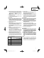
(1) Mounting the hook
Install securely the hook in the groove of power tool
and tighten the screw to fi x the hook fi rmly. (Fig. 21)
Hook
Screw
Groove
Fig. 21
(2) Removing the hook
Loosen the screw fi xing the hook with Philips screw
driver. (Fig. 22)
Screw
Hook
Groove
Fig. 22
16. RFC (Reactive force control)
This product features RFC.
This stops the motor automatically if the tool is jerking
excessively.
The LED light fl ashes to indicate that RFC has been
activated.
If this occurs, release your fi nger from the switch
before restarting. (Fig. 23)
NOTE
●
RFC may not always activate under certain working
conditions or situations.
●
Take care to hold the tool fi rmly to prevent any jerking
motion.
●
RFC may also activate if you change position
suddenly while holding the tool.
Fig. 23
19
English

17. LED light warning signals
This product features functions that are designed
to protect the tool itself as well as the battery. While
the switch is pulled, if any of the safeguard functions
activate during operation, the LED light will blink as
described in Table 9. When any of the safeguard
functions are triggered, immediately remove your
fi nger from the switch and follow the instructions
described under corrective action.
Table 9
Safeguard
Function LED Light Display Corrective Action
Overburden
Protection
On 0.1 second/off
0.1 second
(rapid blinking)
Blinks for
approximately
3 seconds after the
switch has been
released.
If the operating
with the shift knob
set on “2”, adjust
to “1” and continue
operation.
Remove the
cause of the
overburdening.
RFC
On 0.15 second/off
0.15 second ×
3 times/Off
2 seconds
Blinks for
approximately
3 seconds after the
switch has been
released.
Remove the
problem causing
the tool to jerk
excessively.
When operating
the tool, fi rmly hold
the tool to make
sure it doesn't jerk.
Temperature
Protection
On 0.5 second/
Off 0.5 second
(slow blinking)
Blinks while
protection is in
eff ect.
Allow the tool
and battery to
thoroughly cool.
18. Using depth gauge (sold separately) (Fig. 24)
(1) Insert the depth gauge through the side handle’s
mounting hole.
(2) Adjust the length to the hole depth, then clamp in
place using the M5 thumb screw.
Side handle’s
mounting hole
M5 thumb screw
Depth gauge
Tighten
Fig. 24
OPERATIONAL CAUTIONS
Resting the unit after continuous work
(1) The power tool is equipped with a temperature
protection circuit to protect the motor.
Continuous bolt-tightening work may cause the
temperature of the unit to rise, activating the
temperature protection circuit and automatically
stopping operation.
If this happens, allow the power tool to cool before
resuming use.
(2) After use for continuous tightening wood screw works,
rest the unit for 15 minutes or so when replacing the
battery. The temperature of the motor, switch, etc.,
will rise if the work is started again immediately after
battery replacement, eventually resulting in burnout.
20
English
La page charge ...
La page charge ...
La page charge ...
La page charge ...
La page charge ...
La page charge ...
La page charge ...
La page charge ...
La page charge ...
La page charge ...
La page charge ...
La page charge ...
La page charge ...
La page charge ...
La page charge ...
La page charge ...
La page charge ...
La page charge ...
La page charge ...
La page charge ...
La page charge ...
La page charge ...
La page charge ...
La page charge ...
La page charge ...
La page charge ...
La page charge ...
La page charge ...
La page charge ...
La page charge ...
La page charge ...
La page charge ...
La page charge ...
La page charge ...
La page charge ...
La page charge ...
La page charge ...
La page charge ...
La page charge ...
La page charge ...
La page charge ...
La page charge ...
La page charge ...
La page charge ...
La page charge ...
La page charge ...
La page charge ...
La page charge ...
La page charge ...
La page charge ...
La page charge ...
La page charge ...
-
 1
1
-
 2
2
-
 3
3
-
 4
4
-
 5
5
-
 6
6
-
 7
7
-
 8
8
-
 9
9
-
 10
10
-
 11
11
-
 12
12
-
 13
13
-
 14
14
-
 15
15
-
 16
16
-
 17
17
-
 18
18
-
 19
19
-
 20
20
-
 21
21
-
 22
22
-
 23
23
-
 24
24
-
 25
25
-
 26
26
-
 27
27
-
 28
28
-
 29
29
-
 30
30
-
 31
31
-
 32
32
-
 33
33
-
 34
34
-
 35
35
-
 36
36
-
 37
37
-
 38
38
-
 39
39
-
 40
40
-
 41
41
-
 42
42
-
 43
43
-
 44
44
-
 45
45
-
 46
46
-
 47
47
-
 48
48
-
 49
49
-
 50
50
-
 51
51
-
 52
52
-
 53
53
-
 54
54
-
 55
55
-
 56
56
-
 57
57
-
 58
58
-
 59
59
-
 60
60
-
 61
61
-
 62
62
-
 63
63
-
 64
64
-
 65
65
-
 66
66
-
 67
67
-
 68
68
-
 69
69
-
 70
70
-
 71
71
-
 72
72


Hikoki DS18DC Manuel utilisateur
- Catégorie
- Perceuses mixtes sans fil
- Taper
- Manuel utilisateur
dans d''autres langues
- English: Hikoki DS18DC User manual
- español: Hikoki DS18DC Manual de usuario
Documents connexes
-
Hikoki D36DYA Manuel utilisateur
-
-
-
-
-
-
-
-
-