
11
Supported models
• C4-T4IW8-POE 8" T4 In-Wall PoE Touchscreen Power Box
• C4-T4IW10-POE 10" T4 In-Wall PoE Touchscreen
Power
Box
• C4-T4IW8-AC 8" T4 In-Wall AC Touchscreen Power Box
• C4-T4IW10-AC 10" T4 In-Wall AC Touchscreen Power Box
Introduction
This installation guide shows how to install the T4 touchscreen power
box (sometimes called the “mid-box”). The power box is the physical
interface between the touch screen and the wall box.
See other installation guides:
• Wall box for new construction:
ctrl4.co/wallbox-new
• Wall box for retrofit:
ctrl4.co/wallbox-retro
• T4 POE installation guide:
ctrl4.co/t4-inwall-ig
• T4 AC installation guide:
ctrl4.co/t4ac-ig
Box contents
• Power box (to power the T4 touchscreen)
• Two screws (to attach the power box to the wall box)
• Four screws (to attach to standard double-gang box)
• Two wire nuts (AC model only)
Accessories available for purchase
• Pakedge 802.3at/af Gigabit PoE+ Injector (PI-30AT), or Araknis
Networks Gigabit PoE+ Injector
(AN-ACC-INJ-POE-30W), each sold separately.
• Wall box options (sold separately)—Metal and plastic, for new
construction or retrofit installations.
• In-Wall Touchscreen Wall Box Kits - New Construction
• Plastic (C4-NWB57C-P)
• Metal (C4-NWB57C-M)
• In-Wall Touchscreen Wall Box Kits - Retrofit
• Plastic (C4-RWB57C-P)
• Metal (C4-RWB57C-M)
• Third-party products:
• Arlington™ Double Gang Non-Metallic Box - 4 x 4
(FSR404BL)
Wall-box requirements
• Standard 2-gang wall box with a minimum depth of 42 mm (1.65")
and a minimum internal volume of 410 cm3 (25 in3)
• Wall box must be certified by a NRTL and be UL listed to QCMZ or
QCIT category
Warnings
Warning! Install in accordance with all national, state, and
local electrical codes.
AVERTISSEMENT ! Installez selon tous les national, état, et
codes électriques locaux.
Warning! This product generates heat. The room must
have adequate ventilation or the ability to dissipate heat
eectively.
AVERTISSEMENT ! Ce produit produit de la chaleur. La
salle doit avoir à ventilation proportionnée ou la capacité
d’absorber la chaleur ecacement.
Warning! Use this product only in dry locations.
AVERTISSEMENT ! Employez ce produit seulement dans des
endroits secs.
Caution! Improper use or installation can cause DAMAGE OF
PROPERTY.
AVERTISSEMENT ! L’utilisation ou l’installation inexacte peut
causer DAMAGE DE PROPRIÉTÉ.
Important! Using this product in a manner other than outlined
in this document voids your warranty. Further, Control4 is
NOT liable for any damage incurred with the misuse of this
product. Visit snapone.com/legal for more information.
Important ! Utilisant ce produit en quelque sorte autre
que décrit dans ce document vide votre garantie. De plus,
Control4 n’est pas responsable d’aucun dommage encouru
avec l’abus de ce produit. Visitez snapone.com/legal pour
plus d’informations.
Specifications
Model Numbers C4-T4IWMB-AC or C4-T4IWMB-POE
Network
Ethernet or Wi-Fi
• 802.11b/g/n 2.4 GHz
• 802.11a/n/ac 5 GHz
• Security: WEP, WPA/WPA2 PSK, 802.1x EAP, PEAP
Notes: (1) While technically the touchscreen can
use 802.11b, 802.11b is not supported. (2) 802.11n is
recommended for best performance. Even with 802.11n,
broadcasting to several devices will degrade Video
Intercom response time and images. Broadcasting to
additional devices will further degrade performance. See
“Wireless Network Limitations.”
Power supply
PoE: 13W peak (IEEE 802.3af)
AC: 100-240VAC
AC box output: 5V DC 7.5W rms (10W peak)
Dimensions (W × H × D) 127 × 119 × 45 mm (5.0 × 4.67 × 1.77")
Weight 0.13 kg (0.29 lb)
Operating temperature 0 to 40 ˚C (32 to 104 ˚F)
Storage temperature -20 to 70 ˚C (-4 to 158 ˚F)
8" and 10" T4 Series In-Wall Touchscreen Power Box
Installation Guide

2
Requirements
Network
• If using Ethernet: Ethernet network installed and available that
includes a gateway/router/switch. One Ethernet Cat 5/6 cable
that runs from the Ethernet gateway/router/switch to the Ethernet
connection in the touchscreen’s wall box.
• If using Wi-Fi: Wireless network (IEEE 802.11b/g/n) installed and
available with a wireless access point (AP). Security can be WEP,
WPA/WPA2 PSK, 801.1x EAP, or PEAP.
Power
• If using PoE:
• Control4 PoE Injector (model #AC-POE1-B) or another third-
party, UL/ANSI-certified PoE injector or switch.
• Two Ethernet Cat 5/6 cables: (1) one that runs from the
Ethernet gateway/router/switch to the PoE injector/switch and
(2) one that runs from the PoE injector/switch to the Ethernet
connection in the touchscreen’s wall box.
• If using AC:
• Access to in-wall AC power (neutral connection required).
• A 14-gauge electrical wire long enough to pull between the
touchscreen and the power source.
Warning! Use 16 AWG through 10 AWG only
AVERTISSEMENT ! Utiliser 16 AWG par 10 AWG uniquement.
Warning! For supply connections, use wires suitable for at
least 60 °C (140 °F)
AVERTISSEMENT ! Utiliser des fils convenant à une
température de 60 °C pour les connexions dalimentation.
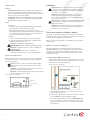
Touchscreen placement
Place the touchscreen in a convenient location at eye level, typically
near the entrance of the room, about 145 to 155 cm (57 to 61 inches)
from the floor (Figure 1).
Note: Consider the camera on the panel and the height of
the people in the home who will use the camera for Video
Intercom.
Important: The top of the touchscreen must be mounted no
higher than 2 m (6.6 ft.) above the floor.
Important : Le haut de l’écran tactile ne doit pas être monté à
plus de 2 m (6,6 pi) au-dessus du sol.
Figure 1: Touchscreen placement
Installation
Important! Before you can complete the instructions below,
you must have an 8" or 10" Touchscreen wall box installed
according to the documentation provided in the wall box kit.
See “Accessories” for details.
Important ! Avant de lire les instruction ci-dessous, il vous
faut un support mural installé suivant la documentation
fournie avec le kit du support mural. Plus de détails dans la
partie << Accessoires >>.
Important! When cutting the opening for the wall box, do not
cut the opening too large. Be conservative and cautiously
enlarge it as needed.
Important ! En coupant l’ouverture pour le support mural,
ne faites pas une ouverture trop grande. Soyez prudent, et
agrandissez la avec précaution.
Power and network installation options
This device uses an Ethernet or Wi-Fi network connection and can be
powered using PoE or AC power. Whichever method you use, you need
to install only one cable going to the power box.
Choose one of the following options to install the power and network
communication.
Option 1: PoE power and Ethernet
PoE supplies DC power on the Ethernet cable using a PoE Injector
(model #AC-POE1-B) or a PoE-enabled port on a network switch. The
touchscreen also works with most third-party PoE injectors. In this
configuration, both power and the network’s data connection travel
along the same cable.
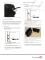
To set up your PoE and Ethernet connection:
1 If you need to install a PoE injector, attach it between the non-PoE
switch and the touchscreen, according to the instructions in the
PoE injector’s documentation (Figure 2).
Figure 2: PoE power and Ethernet
a For the Control4 PoE injector, connect the injector to an AC
outlet using the power cord.
b Connect one of the LAN ports on the network switch to the PoE
injector’s LAN port using Cat 5/6 Ethernet cable.
c Pull a cable going from the PoE injector’s PWR LAN-OUT port
to the location where you want to install the touchscreen, then
through one of the touchscreen’s left-side wall box knockout
holes (Figure 3).
Touchscreen
Power source for AC
or PoE

3
Figure 3: Insert Ethernet cable into power box
Note: The Ethernet port on the power box does not have
functioning indicator LEDs.
Option 2: PoE power and Wi-Fi
If you’re unable to run a network cable from the network switch to the
touchscreen location, you can install a PoE injector to use household
wiring as the power source, and run a network cable from the injector
to the touchscreen power box. The touchscreen works with the
Control4 PoE Injector or any compatible third-party PoE Injector. This
configuration uses Wi-Fi for communication with the network.
To set up a PoE injector:
1 Attach the PoE injector between the non-PoE switch and the
touchscreen, according to the instructions in the PoE injector’s
documentation (Figure 4).
Figure 4: PoE power and Wi-Fi
a For the Control4 PoE injector, connect the injector to an AC
outlet using the power cord.
b Connect one of the LAN ports on the network switch to the PoE
injector’s LAN port using Cat 5/6 Ethernet cable.
c Pull a cable going from the PoE injector’s PWR LAN-OUT port
to the location where you want to install the touchscreen, then
through one of the touchscreen’s left-side wall box knockout
holes (Figure 3, above).
Option 3: Wi-Fi with AC power
To connect AC power:
1 Place the touchscreen above a power source, for example, an
outlet. Make sure the location is within distance of your Wi-Fi
signal. (Figure 5).
Figure 5: AC power with Wi-Fi
2 Prepare the plastic power box for installation into the wall box by
inserting the AC power cable into the power box.
Caution: Use only 14 AWG wire for AC connections. For supply
connections, use wires suitable for at least
60 °C (140 °F).
3 Connect the wires to the AC power source for the touchscreen
according to national and local electrical codes. Installation may
require alternative wires.
4 Pull the power cable through a right-side knockout hole of the
wall box to the wire leads on the power box.
5 Strip the black and white power wire ends to 6 mm (about 1/4”),
as necessary.
6 Use wire nuts to connect the AC power wiring to the two wired
power leads from the power box.
7 If using a plastic wall box with an exposed bare copper ground,
wrap the ground in electrical tape or heat shrink tape/tubing. If
using a metal wall box, attach the ground wire to the wall box.
Place touchcreen here
Controller
Switch
Wireless
access point
Wi-Fi
PoE
injector
PoE
injector
Place touchcreen here
Controller
Switch
Wireless
access point
Wi-Fi

control4.com | 888.400.4070
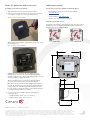
Attach the power box and touchscreen
To install the power box into the wall box:
1 Align and bend the wires to fit them inside the wall box.
2 Slide the power box into the wall box, then secure the power box
to the wall box using the two screws provided (Figure 6).
Figure 6: Secure power box to wall box
OR, if using a standard double-gang wall box, use the four screws
provided (Figure 7).
Figure 7: Secure power box to wall box
Caution: Do not use an electric driver to tighten the screws.
Overtightening can result in the power box becoming slightly
warped, resulting in a poor electrical docking connection. Use only
a hand screwdriver to tighten the screws.
Tip: If overtightened screws result in the power box warping,
loosen the screws until the power box is flush to the wall.
Note: The power box must be installed straight, level, and flush to
the wall. The mounting holes of the power box may be drilled out
using a 5 mm (7/32” ) drill bit to align with the holes in the wall
box. This may be needed if the wall box is not installed squarely or
is misaligned during installation of drywall
3 See your touchscreen installation guide for information on
touchscreen setup:
• T4 POE installation guide:
ctrl4.co/t4-inwall-ig
• T4 AC installation guide:
ctrl4.co/t4ac-ig
Additional resources
The following resources are available for additional support.
• Knowledgebase and forums in Technician Community:
tech.control4.com
• Technical Support
• Control4 website: www.control4.com
• Composer documentation in its online help.
Warranty and legal notices
Find details of the product’s Limited Warranty and other safety, patent,
and legal resources at snapone.com/legal or request a paper copy
from Customer Service at 866.424.4489.
WALL BOX INSTALL: NEW CONSTRUCTION
ctrl4.co/wallbox-new
WALL BOX INSTALL: RETROFIT
ctrl4.co/wallbox-retro
200-00726-A
20220119DH
Copyright ©2022, Snap One, LLC. All rights reserved. Snap One and its respective logos are registered trademarks or trademarks of Snap One, LLC (formerly known as
Wirepath Home Systems, LLC), in the United States and/or other countries. 4Store, 4Sight, Control4, Control4 My Home, SnapAV, Araknis Networks, BakPak, Binary, Dragonfly,
Episode, Luma, Mockupancy, Nearus, NEEO, Optiview, OvrC, Pakedge, Sense, Strong, Strong Evolve, Strong VersaBox, SunBriteDS, SunBriteTV, Triad, Truvision, Visualint,
WattBox, Wirepath, and Wirepath ONE are also registered trademarks or trademarks of Snap One, LLC. Other names and brands may be claimed as the property of their
respective owners. Snap One makes no claim that the information contained herein covers all installation scenarios and contingencies, or product use risks. Information within
this specification subject to change without notice.
A
126.9 mm (5.00 in.)
118.8 mm (4.68 in.)
59.2 mm (2.33 in.)
24.0 mm (0.94 in.)
30.6 mm (1.21 in.)
22.2 mm (0.88 in.)
-
 1
1
-
 2
2
-
 3
3
-
 4
4


dans d''autres langues
Documents connexes
Autres documents
-
Extron TLP Pro 300M Manuel utilisateur
-
Extron TLP Pro 525T Manuel utilisateur
-
Extron TLP Pro 725M Manuel utilisateur
-
-
Extron TLC Pro 1026M Manuel utilisateur
-
-
-
-