
To see operational and troubleshooting information and videos,
go to www.hzsupport.com
Dated receipt required for warranty replacement.
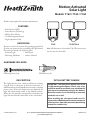
FEATURES
• Solar Powered LED
• Power Reserve Technology
• Wall or Eave Mount
• Cord Management System
• Night Operation Only
UNPACKING
Be sure to remove all contents from packaging and verify
all items are present before assembling this light xture.
is package includes the following items:
• Security Light • Solar Panel
• Mounting Hardware • Owner’s Manual
© 2016 HeathCo LLC 208824-01A
Motion-Activated
Solar Light
Models: 7162 / 7163 / 7164
HARDWARE INCLUDED
Mounting Screw (x4) Wall Anchor (x4)
WW
7162 7163/7164
DESCRIPTION
is light operates from a built-in lithium-ion battery
charged from a solar panel. It will also hold three “C”
alkaline batteries (not included) which are used as a backup
power source. If the solar battery becomes depleted, the
light will automatically switch to the alkaline batteries.
When the solar panel has recharged the solar battery, the
light will automatically switch back to the solar battery.
INITIAL BATTERY CHARGE
IMPORTANT: The solar panel requires full, direct
sunlight to charge the battery. Clouds, rain, snow,
and other weather conditions may not allow the
solar panel to completely recharge the battery.
Other obstructions such as buildings or trees may
block the sun as well.
When installing the solar panel, make sure it is
aimed as described below with a minimum amount
of obstructions. If possible, mount the panel facing
toward the southern sky.
Note: All illustrations show model 7163. e instructions
are the same for all models.

2 To see operational and troubleshooting information and videos,
go to www.hzsupport.com
208824-01
IMPORTANT SAFETY AND
INSTALLATION INFORMATION
Before installing security light, read all instructions carefully
and keep owner’s manual for future reference.
• WARNING: To prevent possible SERIOUS INJURY
or DEATH never allow small children near batteries.
If battery is swallowed, immediately notify a doctor.
• WARNING: DO NOT mix old and new batteries. DO
NOT mix battery types - such as alkaline, heavy duty,
and rechargeable - in a single device. Battery leakage
may occur.
• WARNING: DO NOT DISPOSE OF BATTERIES
IN FIRE. BATTERIES MAY EXPLODE OR LEAK.
• CAUTION: Burn hazard. Allow the light xture to cool
before touching.
• NOTICE: When replacing batteries, recycle used batteries
or dispose of them in accordance with local regulations.
• is xture is designed for outdoor installation and
should be mounted to a wall or eaves.
• To achieve best results, this xture should be mounted
8 feet (2.4 meters) above the ground.
• Do not cut the solar panel wire. Discontinue use if the
wire becomes frayed or broken.
• Do not immerse components in liquid.
• Do not use any other charging device other than the
single solar charging panel provided with this light.
Doing so may result in injury or damage to the light
and voids any warranty.
• Position the cord so that it is securely fastened and will
not result in a hazard (such as tripping).
is device complies with Part 15 of the FCC Rules.
Operation is subject to the following two conditions: (1)
this device may not cause harmful interference, and (2)
this device must accept any interference received, including
interference that may cause undesired operation.
• PRIOR TO USE, the solar panel will need to be con-
nected to the battery (see Installation instructions)
and the battery will require 3 to 7 days of full sun to
completely charge with the control dial in the OFF
position. Remove the rubber plug from the bottom of
the light xture and insert the end of the solar panel cable
into the opening. If possible, aim the solar panel toward
the south and tilt it approximately 50° from horizontal.
If the solar panel cannot be aimed toward the south, then
tilt the panel approximately 30° if possible.
• Actual operating time will vary depending upon how
frequently the light is turned on by the motion sensor.
•
Solar lighting is not designed to equal standard 120V light-
ing. e amount of light output is reduced to allow the sun
time to fully recharge the battery between lighting cycles.
• Solar collection is only eective in direct sunlight. Every
hour the light is on requires a minimum of 16 hours of
sunlight charging. Solar panels collect less than 10% of
the sun’s energy.
MOUNTING LOCATION
e most important thing to remember for the operation
of your solar powered motion sensing light is that it works
from the power received from direct sunlight. e more
direct sunlight the solar panel receives in a day, the longer
the light will operate.
Solar Light Fixture
e main unit contains the LEDs, motion sensor, and
battery. When deciding where to mount this unit, keep
in mind that the motion sensor that activates the light
has a “eld of vision” of 40 feet (12 meters) in front of the
light and about 180° detection angle at a surrounding air
temperature of 77° F (25 °C).
Solar Panel
e solar panel converts the sun’s energy into electricity,
thus charging the battery stored in the solar light xture.
e solar panel requires direct sunlight falling onto the
face of the solar panel for as long as possible over the
course of the day.
When choosing the location for the solar panel, make sure
it is aimed toward the south and is tilted to a suitable angle
to allow as much direct sunlight to fall upon it as possible.
Make sure there is a minimum amount of obstructions
between the solar panel and the sun.
Also, make sure your solar panel location is not too far
away from the solar light xture for the wires to reach
and connect.

To see operational and troubleshooting information and videos, 3
go to www.hzsupport.com
208824-01
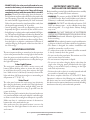
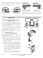
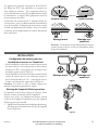
Note: Light xture and sensor should be mounted as shown
above when installed (depending upon type of installation).
Least Sensitive Most Sensitive
MotionMotion
Sensor
Wall Mount Eave Mount
Wall Mount Eave Mount
W
E
e motion sensor on this light xture detects “motion”
by the movement of heat across the coverage area. e
motion sensor is more sensitive to the movement of heat
moving across the coverage area and less sensitive to the
movement of heat directly towards it.
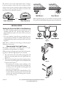
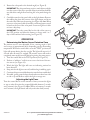
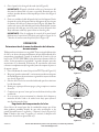
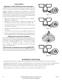
INSTALLATION
Setting the Sensor for Wall or Eave Mounting
• For wall mounting, turn the ring around the sensor
clockwise until the “W” and the single indicator is
aligned with the mark on the front of the sensor (see
Figure 1).
• For eave mounting, turn the ring around the sensor
counterclockwise until the “E” and the double indicator
is aligned with the mark on the front of the sensor. (see
Figure 1).
Note: ere is a detent at each setting to indicate proper
alignment of the sensor.
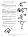
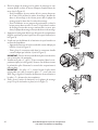
Mounting the Solar Light Fixture
is xture comes with a mounting plate. It is pre-
assembled on the light xture for shipping.
Make sure there is enough vertical space above the mount-
ing plate to allow the light xture to be mounted.
1. Press the bottom tab of the wall mounting plate and
slide the mounting plate from the light body (see
Figure 2).
2. Place the mounting plate against the mounting surface
and ensure the mounting plate is level. Mark the hole
locations (see Figure 3).
• If mounting to a wooden surface, drill two 3/32
in. holes into the mounting surface. Install the two
mounting screws through the mounting plate and
into the mounting surface.
• If mounting to wall board or brick, drill two 7/32
in. holes into the mounting surface. Insert the wall
anchors and attach the mounting plate using the
two mounting screws.
W
E
W
Figure 1
Figure 2
Figure 3
UP
OPEN
PRESS TO CLOSE

4 To see operational and troubleshooting information and videos,
go to www.hzsupport.com
208824-01
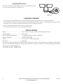
Figure 4
Figure 5
Figure 6
Figure 7
Figure 8
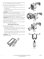
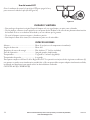
3. Press up on the battery compartment cover locking tab and swing
the cover out and down to remove (see Figure 4).
4. is light xture is shipped with the internal, rechargeable, Li-ion
battery disconnected from the light.
• Gently press down on the wiring harness as shown by arrow
1 (see Figure 5).
• Slide the mail connector into the female connector as shown
in arrow 2 (see Figure 5).
IMPORTANT: Once the the solar battery harness is connected,
there will be no need to touch this harness again.
5. Install three, 1.5V “C” batteries (not included) into the battery
compartment (see Figure 6). Make sure the polarity of the bat-
teries is correct.Replace the battery compartment cover.
IMPORTANT: e “C” batteries are used when the rechargeable
solar battery is depleted. When the “C” batteries are depleted, a
red LED will ash inside the motion sensor and the “C” batter-
ieswill need to be replaced.
6. Slide the rear of the light xture down onto the mounting plate
until it snaps into place (see Figure 7).
Mounting the Solar Panel
1. Place the solar panel against the mounting surface and mark the
mounting holes (see Figure 8).
• If mounting to a wooden surface, drill two 3/32 in. holes into
the mounting surface. Install the two mounting screws through
the base and into the mounting surface.
• If mounting to wall board or brick, drill two 7/32 in. holes
into the mounting surface. Insert the wall anchors and attach
the base using the two mounting screws.
IMPORTANT: Caulk around the base and on top of the screw
heads after installation.
OPEN
PRESS TO CLOSE
OPEN
PRESS TO CLOSE
1
2
1
2
W
UP

To see operational and troubleshooting information and videos, 5
go to www.hzsupport.com
208824-01
Figure 10
Figure 9
Figure 13
Figure 11
Figure 12
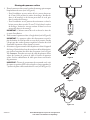
2. Rotate the solar panel to the desired angle (see Figure 9).
IMPORTANT:e solar panel must receive as much direct sunlight
over the course of the day as possible. Keep in mind that shadows
may block the sunlight from reaching the solar panel during the
day.
3. Carefully route the solar panel cable to the light xture. Remove
the rubber plug from the bottom of the light xture and insert
the end of the cable into the opening (see Figure 10). Note: Wrap
any excess solar panel cable around the cord management system
located on the rear of the solar panel. Leave enough loose cable
to form a drip loop.
IMPORTANT: Turn the control dial on the side of the sensor to
the OFF position and allow the battery to charge with 3 to 7
days of full sunshine before testing (see Figure 11).
OPERATION
Determining the Motion Sensor Detection Zone
e motion sensor is non-adjustable. It has a sensing angle of 180°
and a range of approximately 40 ft. depending on the surrounding
temperature. When the control dial is set to the “TEST” position, the
light will operate during the day or night. e light will stay on for 5
seconds after all motion is stopped. e motion sensor will need to
completely warm up (60 seconds) before beginning the setup process.
1. Turn the control dial to the TEST position (see Figure 11).
2. Perform a “walk test”: walk in an arc across the front of the mo-
tion sensor (see Figure 12).
3. Watch the light. e light will come on indicating motion has
been detected.
4. Stop, wait for the light to turn o, and then begin walking again.
5. Continue this process until the detection zone has been established.
6. If needed, gently grasp the lamp heads and move them from side
to side or up and down to adjust the light coverage area.
Adjusting the Light Timer
Turn the control dial to set the amount of time you want the lights
to stay on after all motion has stopped (adjustble between 5 seconds
and 5 minutes) (see Figure 13). Note: When set between 5 seconds
and 5 minutes, the light xture will only work after dark (sunset).
W
T
E
S
T
5
S
O
F
F
5
M
i
n
E
W
W
T
E
S
T
5
S
O
F
F
5
M
i
n

6 Para ver más información y vídeos sobre operación y resolución de problemas,
visite www.hzsupport.com
208824-01
CARE AND CLEANING
• To prolong the original appearance, clean the light xture with clear water and a soft, damp cloth only.
• Do not use paints, solvents, or other chemicals on this light xture. ey could cause a premature deterioration of the
nish. is is not a defect in the nish and will not be covered by the warranty.
• Do not spray the light xture with a hose or power washer.
• To clean the camera lens, use a dry, microber cloth only.
SPECIFICATIONS
Range ...................................................Up to 40 ft. (12 m) [varies with surrounding temperature].
Sensing Angle.......................................Up to 180°
Reserve Power Requirements ...............“C” Alkaline Batteries (3x) (not included)
Operating Modes .................................OFF, TEST, TIMER
Timer ...................................................5 seconds to 5 minutes (adjustable)
Test Timer ............................................8 Seconds
is device complies with Part 15 of the FCC Rules. Operation is subject to the following two conditions: (1) this device
may not cause harmful interference, and (2) this device must accept any interference received, including interference
that may cause undesired operation.
CAN ICES-005 (B) / NMB-005 (B)
Using the OFF Control
Turn the control dial to the OFF position to turn the light o and
to conserve the battery life (see Figure 14).
Figure 14
W
T
E
S
T
5
S
O
F
F
5
M
i
n

To see operational and troubleshooting information and videos, 7
go to www.hzsupport.com
208824-01
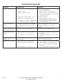
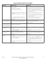
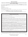
TROUBLESHOOTING GUIDE
SYMPTOM POSSIBLE CAUSE SOLUTION
e light will not come on. 1. e control dial is set to the OFF position.
2. Batteries are dead.
3. Solar panel positioned wrong.
4. Daylight turn-o (photocell) is in eect.
5. Motion sensor is positioned wrong.
6. Surrounding air temperature is greater than
122° F (50° C) or less than -4° F (-20° C).
1. Turn the control dial to select an amount of
time for the light timer.
2. Replace the three “C” alkaline batteries.
3. Position and angle solar panel so that it gets
plenty of direct sunlight for most of the day,
if not the entire day.
4. Recheck after dark.
5. Reposition light so motion sensor is
positioned toward the area of movement.
6. e light will operate normally inside the
specied temperature range.
Light is not as bright as
normal. e rechargeable solar battery is low and the
light is running o of the three “C” backup
batteries.
Once the rechargeable solar battery is suciently
recharged, the light will come on at full
brightness.
ere is a red blinking light
inside the motion sensor. e three “C” batteries are running low on
power. Replace the three “C” alkaline batteries.
e light comes on during
the day. 1. Light control is mounted in a dark location.
2. e motion sensor is in “TEST” mode.
1. Relocate light control to an area that receives
more light.
2. Turn the control dial between 5 seconds and
5 minutes.
e light comes on for no
apparent reason. Motion sensor may be sensing small animals or
automobile trac. Reposition light so motion sensor is positioned
away from the area of movement.
e lights ash on and o. 1. Light control may be sensing shadows.
2. e motion sensor is in “TEST” mode.
3. e control dial is set to 5 seconds.
1. Relocate light to an area away from shadows.
2. While in TEST mode, the light only stays on
for 8 seconds. Set light timer control dial to
desired time.
3. Set the control dial to a longer time setting.

8 To see operational and troubleshooting information and videos,
go to www.hzsupport.com
208824-01
TECHNICAL SERVICE
Please call 1-800-858-8501 (English speaking only) for assistance before returning product to store.
If you experience a problem, follow this guide. You may also want to visit our Web site at: www.hzsupport.com. If the
problem persists, call* for assistance at 1-800-858-8501 (English speaking only), 8:00 AM to 5:00 PM CST (M-F).
You may also write* to:
HeathCo LLC, P.O. Box 90045, Bowling Green, KY 42102-9045
ATTN: Technical Service
* If contacting Technical Service, please have the following information available: Model Number, Date of Purchase,
and Place of Purchase.
No Service Parts Available for this Product
Please keep your dated sales receipt, it is required for all warranty requests.
THREE YEAR LIMITED WARRANTY
is is a “Limited Warranty” which gives you specic legal rights. You may also have other rights which vary from
state to state or province to province.
For a period of three years from the date of purchase, any malfunction caused by factory defective parts or work-
manship will be corrected at no charge to you.
Not Covered - Repair service, adjustment and calibration due to misuse, abuse or negligence, light bulbs, batteries,
and other expendable items are not covered by this warranty. Unauthorized service or modication of the product
or of any furnished component will void this warranty in its entirety. is warranty does not include reimbursement
for inconvenience, installation, setup time, loss of use, unauthorized service, or return shipping charges.
is warranty covers only HeathCo LLC assembled products and is not extended to other equipment and com-
ponents that a customer uses in conjunction with our products.
THIS WARRANTY IS EXPRESSLY IN LIEU OF ALL OTHER WARRANTIES, EXPRESS OR IMPLIED,
INCLUDING ANY WARRANTY, REPRESENTATION OR CONDITION OF MERCHANT ABILITY
OR THAT THE PRODUCTS ARE FIT FOR ANY PARTICULAR PURPOSE OR USE, AND SPECIFI-
CALLY IN LIEU OF ALL SPECIAL, INDIRECT, INCIDENTAL, OR CONSEQUENTIAL DAMAGES.
REPAIR OR REPLACEMENT SHALL BE THE SOLE REMEDY OF THE CUSTOMER AND THERE
SHALL BE NO LIABILITY ON THE PART OF HEATHCO LLC FOR ANY SPECIAL, INDIRECT,
INCIDENTAL, OR CONSEQUENTIAL DAMAGES, INCLUDING BUT NOT LIMITED TO ANY
LOSS OF BUSINESS OR PROFITS, WHETHER OR NOT FORESEEABLE. Some states or provinces do
not allow the exclusion or limitation of incidental or consequential damages, so the above limitation or exclusion
may not apply to you.
Please keep your dated sales receipt, it is required for all warranty requests.
HeathCo LLC reserves the right to discontinue products and to change specications at any time without incurring any
obligation to incorporate new features in products previously sold.

Para ver más información y vídeos sobre operación y resolución de problemas, 9
visite www.hzsupport.com
208824-01
© 2016 HeathCo LLC 208824-01 S
Se necesita el recibo fechado para reemplazo bajo garantía.
CARACTERÍSTICAS
• LED con energía solar
• Tecnología de reserva de energía
• Montaje en pared o alero
• Sistema de conducción de cables
• Sólo para funcionamiento nocturno
DESEMPAQUE
Asegúrese de retirar todo el contenido del empaque y
vericar que todos los elementos estén incluidos antes de
ensamblar este aparato de luz. Este paquete incluye los
siguientes elementos:
• Luz de seguridad • Panel solar
• Ferretería de montaje • Manual del propietario
Luz solar activada
por movimiento
Modelos: 7162 / 7163 / 7164
FERRETERÍA INCLUIDA
Tornillo de montaje (x4) Ancla de pared (x4)
WW
7162 7163/7164
DESCRIPCIÓN
Esta luz funciona con una batería de iones de litio incor-
porada y cargada por un panel solar. También contiene 3
pilas alcalinas tipo “C” (no incluidas) que son usadas como
fuente de energía eléctrica de respaldo. Si la pila solar se
agota, la luz cambiará automáticamente a pilas alcalinas.
Cuando el panel solar ha recargado a la pila solar, la luz
volverá a cambiarse automáticamente al funcionamiento
con la pila solar.
CARGA INICIAL DE LA BATERÍA
IMPORTANTE: El panel solar requiere luz de sol
directa y total para cargar la batería. Condiciones
climatológicas como nubes, lluvia, nieve y otros
pueden evitar que el panel solar recargue comple-
tamente la batería. Otros obstáculos tales como
edicios o árboles también pueden bloquear el sol.
Al instalar el panel solar, asegúrese de que esté
orientado como se describe a continuación con
una mínima cantidad de obstáculos. De ser posi-
ble, monte el panel con dirección al cielo sureño.
Nota: Todas las ilustraciones muestran el modelo 7163.
Las instrucciones son las mismas para todos los modelos.

10 Para ver más información y vídeos sobre operación y resolución de problemas,
visite www.hzsupport.com
208824-01
También asegúrese que la ubicación de su panel solar no
esté demasiado alejada de la lámpara solar para que los
cables puedan alcanzar y conectarse.
INFORMACIÓN IMPORTANTE DE
SEGURIDAD E INSTALACIÓN
Antes de instalar la luz de seguridad, lea todas las instruc-
ciones con cuidado y guarde el manual del propietario para
futura referencia.
• ADVERTENCIA: Para evitar posibles LESIONES
GRAVES o LA MUERTE nunca deje que los niños
pequeños estén cerca de las pilas. Si alguien ingiere una
pila, notique inmediatamente al médico.
• ADVERTENCIA: NO mezcle las pilas viejas con las
nuevas. NO mezcle diferentes tipos de pilas - tales
como alcalinas, muy resistentes y recargables - en un
solo dispositivo. Pueden causar goteo de las pilas.
• ADVERTENCIA: NO TIRE LAS PILAS AL FUEGO.
LAS PILAS PUEDEN EXPLOTAR O GOTEAR.
• PRECAUCIÓN: Peligro de quemaduras. Deje que el
aparato de luz se enfríe antes de tocarlo.
• AVISO: Cuando reemplace las baterías, recicle las bate-
rías usadas o disponga de ellas de acuerdo a las normas
locales.
• Este aparato está diseñado para una instalación al aire
libre y se lo debe montar en una pared o en aleros.
• Para lograr los mejores resultados, este aparato debe
montarse a 8 pies (2,4 metros) por encima del suelo.
• No corte el cable del panel solar. Deje de usar si el cable
se deshilacha o se rompe.
• No sumerja los componentes en líquidos.
• No use ningún otro dispositivo de carga que no sea el
panel de carga solar sencillo provisto con esta lámpara.
Si usa otro dispositivo, puede producirle una lesión o
un daño a la lámpara y anular cualquier garantía.
• Coloque el cordón para que esté sujeto de forma segura
y no resulte peligroso (como una desconexión).
Este aparato cumple con la Parte 15 de las Reglas de la
FCC. La operación está sujeta a las dos siguientes con-
diciones: (1) este aparato no puede causar interferencias
perjudiciales y (2) este aparato debe aceptar cualquier
interferencia recibida, incluyendo una interferencia que
pueda causar un funcionamiento indeseado.
El detector de movimiento de este aparato de luz detecta
“movimiento” debido al movimiento del calor a través
del área de cobertura. El detector de movimiento es más
• ANTES DE SU USO, el panel solar debe ser conectado
a la batería (vea las instrucciones de instalación) y
la batería requerirá de 3 a 7 días de pleno sol para
cargarse por completo con el disco de control en
la posición OFF. Retire el tapón de caucho de la parte
inferior de la lámpara e inserte el extremo del cable del
panel solar en la abertura. Si es posible, apunte el panel
solar hacia el sur e inclínelo por casi 50° del nivel ho-
rizontal (vea la ilustración en la siguiente página). Si al
panel solar no se le puede apuntar hacia el sur, entonces
incline el panel por casi 30° si es posible.
• El tiempo real de funcionamiento dependerá de cuan
frecuentemente el detector de movimiento prende la luz.
• La luz solar no se iguala al alumbrado estándar de 120
voltios. La cantidad de producción de luz se reduce para
permitir que el sol recargue por completo la batería entre
los ciclos de alumbrado.
• La colección solar es solo efectiva bajo la luz directa del
sol. Por cada hora que la luz está prendida requiere un
mínimo de 16 horas de carga de luz solar. Los paneles
solares recolectan menos del 10% de la energÌa solar.
LOCALIZACIÓN DEL MONTAJE
La cosa más importante que hay que recordar para la opera-
ción de su lámpara detectora de movimiento alimentada por
luz solar es que trabaja con la energía recibida directamente
del sol. Mientras el panel solar más directamente recibe
la luz solar durante un día, más tiempo funcionará la luz.
Lámpara Solar
La unidad principal contiene LEDs, detector de movi-
miento y baterías. Cuando se decida dónde instalar la
unidad, recuerde que el detector de movimiento que activa
la luz tiene un “campo de visión” de 40 pies (12 metros) al
frente de esta luz y más o menos un ángulo de detección de
180º a una temperatura del aire ambiente de 77ºF (25ºC).
Panel Solar
El panel solar convierte la energía solar en electricidad,
cargando así a la batería guardada en la lámpara solar. El
panel solar requiere que la luz solar incida directamente en la
supercie del panel el mayor tiempo posible a lo largo del día.
Cuando escoja el sitio para el panel solar, asegúrese que
este panel esté apuntando hacia el sur e inclinado a un
ángulo adecuado que permita que incida directamente
tanta luz solar como sea posible. Asegúrese que haya la
menor cantidad de obstrucciones entre el panel solar y el sol.

Para ver más información y vídeos sobre operación y resolución de problemas, 11
visite www.hzsupport.com
208824-01
sensible a la circulación del calor que se mueve a través
del área de cobertura y menos sensible a la circulación del
calor que va directamente hacia él.
Nota: La lámpara y el sensor debe montarse como se indica
arriba, una vez instalado (según el tipo de instalación).
Lo menos sensible Lo más sensible
Montaje en pared Montaje en alero
Montaje en Montaje en
pared alero
W
E
Detector
Movimiento Movimiento
INSTALACIÓN
Regulación del detector para montaje en
pared y en alero
• Para montaje en pared, gire el anillo alrededor del de-
tector en sentido horario hasta que la “W” y el indicador
simple estén alineados con la marca de la parte frontal
del detector (vea la Figura 1).
• Para el montaje en alero, gire el anilloalrededor del
detector en sentido antihorario hasta que la “E” y el
indicador doble estén alineados con la marca de la parte
frontal del detector (vea la Figura 1).
Nota: Hay un bloqueo en cada regulación que indica el
alineamiento correcto del detector.
Montaje de la lámpara solar
El aparato viene con una placa de montaje. Está premontado
en la lámpara para ser enviado.
Esté seguro que haya suciente espacio vertical por encima
de la placa de montaje que permita montar la lámpara.
1. Pulse la lengüeta inferior de la placa de montaje en
pared y deslice la placa de montaje del cuerpo del
aparato (vea la Figura 2).
2.
Coloque la placa de montaje contra la supercie de mon-
taje y asegúrese de que la placa de montaje esté nivelada.
Marque los sitios para los oricios (vea la Figura 3).
• Si se monta sobre una supercie de madera, taladre
dos oricios de 3/32 pulgadas en la supercie de
montaje. Instale los dos tornillos de montaje que
atraviesen la plancha de montaje hasta llegar a la
supercie de montaje.
• Si el montaje es sobre tabla de bra prensada o sobre
ladrillo, taladre dos oricios de 7/32 pulgadas en
W
E
W
Figura 1
Figura 2
Figura 3
UP
OPEN
PRESS TO CLOSE

12 Para ver más información y vídeos sobre operación y resolución de problemas,
visite www.hzsupport.com
208824-01
la supercie de montaje. Inserte los anclajes de pared y je la
placa de montaje usando los dos tornillos de montaje.
3. Presione hacia arriba en la aleta de bloqueo de tapa del compar-
timento de la pila y gire la tapa hacia afuera y abajo para retirarla
(vea la Figura 4)
.
4. Este aparato de luz está equipado con una pila interna y recargable
de litio-ion que se desconecta desde la luz.
• Presione hacia abajo con suavidad sobre el arnés de cables
como lo muestra la echa1
(vea la Figura 5)
.
• Inserte el conector principal en el conector hembra como lo
muestra la echa 2
(vea la Figura 5)
.
IMPORTANTE: Una vez que está conectado el arnés de la pila
solar, no habrá necesidad de tocar este arnés de nuevo.
5. Instale tres pilas “C” de 1,5V (no incluidas) en el compartimiento
de pilas
(vea la Figura 6)
. Asegúrese que la polaridad de las pilas
sea correcta. Vuelva a colocar la tapa del compartimento de pilas.
IMPORTANTE: Las pilas tipo “C” son usadas cuando la pila solar
recargable está agotada. Cuando las pilas tipo “C” están agotadas,
el LED rojo destellará dentro del detector de movimientoy las
pilas tipo “C” necesitarán ser reemplazadas.
6. Deslice la parte de atrás del aparato de luz hacia abajo sobre la
placa de montaje hasta que cierre a presión en su sitio
(vea la
Figura 7)
.
Montaje del panel solar
1. Coloque el panel solar contra la supercie de montaje y marque
los oricios de montaje
(vea la Figura 8)
.
• Si se monta sobre una supercie de madera, taladre dos oricios
de 3/32 pulgadas en la supercie de montaje. Instale los dos
tornillos de montaje que atraviesen la base hasta llegar a la
supercie de montaje.
• Si se monta sobre tabla de bra prensada o sobre ladrillo, tala-
dre dos oricios de 7/32 pulgadas en la supercie de montaje.
Inserte anclas de pared y sujete la base con dos tornillos de
montaje.
IMPORTANTE: Calafatee alrededor de la base y en la parte superior
de las cabezas de los tornillos luego de la instalación.
Figura 4
Figura 5
Figura 6
Figura 7
Figura 8
OPEN
PRESS TO CLOSE
OPEN
PRESS TO CLOSE
1
2
1
2
W
UP

Para ver más información y vídeos sobre operación y resolución de problemas, 13
visite www.hzsupport.com
208824-01
2. Gire el panel solar al ángulo deseado
(vea la Figura 9)
.
IMPORTANTE: El panel solar debe recibir en el transcurso del
día tanta luz directa del sol como sea posible. Recuerde que las
sombras pueden durante el día impedir que la luz solar llegue al
panel solar.
3. Guíe con cuidado el cable del panel solar hacia la lámpara. Retire
el tapón de cauchode la parte inferior del aparato de luz e inserte
el extremo del cable en la abertura
(vea la Figura 10)
. Nota: En-
vuelva todo exceso del cable del panel solar alrededor del sistema
de manejo del cable que está en la parte de atrás del panel solar.
Deje suciente cable ojo para formar un lazo de goteo.
IMPORTANTE: Gire el cuadrante de control de la parte lateral
del detector a la posición OFF y deje que la pila se cargue de 3 a
7 días de sol intenso antes de probar
(vea la Figura 11)
.
OPERACIÓN
Determinación de la zona de detección del detector
de movimiento
El detector de movimiento no es regulable. Tiene un ángulo de detección
de 180° y un alcance de aproximadamente 40 pies dependiendo de la
temperatura circundante. Cuando el cuadrante de control se ja en
la posición “TEST” (PRUEBA), la luz funcionará durante el día o la
noche. La luz permanecerá encendida 5 segundos después que todo
movimiento se ha detenido. El detector de movimiento necesitará
calentarse completamente (60 segundos) antes de empezar el proceso
de puesta a punto.
1. Gire el cuadrante de control a la posición TEST (vea la Figura 11).
2. Haga una “prueba caminando”: camine transversalmente a la parte
frontal del detector de movimiento siguiendo la trayectoria de un
arco
(vea la Figura 12)
.
3. Observe la luz. La luz se encenderá indicando que el movimiento
ha sido detectado.
4. Deténgase, espere que la luz se apague, y luego empiece a caminar
de nuevo.
5. Continúe este proceso hasta que la zona de detección haya sido
establecida.
6. Si es necesario, sujete suavemente los cabezales de la lámpara y
muévalas de lado a lado o de arriba hacia abajo para ajustar el
área de cobertura de la luz.
Regulación del temporizador de la luz
Gire el disco de control para jar la cantidad de tiempo que la luz
debe quedarse prendida después de que todo movimiento se ha
parado (ajustable entre 5 segundos y 5 minutos). (vea la Figura 13).
Nota: Cuando se je entre 5 segundos y 5 minutos, la lámpara sólo
funcionará al anochecer (puesta del sol).
Figura 10
Figura 9
Figura 13
Figura 11
Figura 12
W
T
E
S
T
5
S
O
F
F
5
M
i
n
E
W
W
T
E
S
T
5
S
O
F
F
5
M
i
n

14 Para ver más información y vídeos sobre operación y resolución de problemas,
visite www.hzsupport.com
208824-01
Figura 14
Uso del control OFF
Gire el cuadrante de control a la posición OFF para apagar la luz y
para conservar la vida de la pila
(vea la Figura 14)
.
CUIDADO Y LIMPIEZA
• Para prolongar la apariencia original, limpie la lámpara solo con agua limpia y un paño suave y húmedo.
• No use pinturas, solventes ni otros químicos en este aparato de luz. Podrían ser la causa de una prematura deterioración
del acabado. Esto no es un defecto del acabado y no será cubierto por la garantía.
• No rocíe la lámpara con una manguera o lavadora a presión.
• Para limpiar la lente de la cámara, use solamente un paño seco de microbra.
ESPECIFICACIONES
Alcance ......................................................... Hasta 12 m (varía con la temperatura circundante).
Angulo de detección ..................................... Hasta 180°
Requisitos de reserva de energía .................. Pilas alcalinas “C” (3x) (no incluidas)
Fases de Operación ....................................... Apagado, prueba, temporizador
Temporizador ............................................... 5 segundos a 5 minutos (regulable)
Temporizador de prueba ............................... 8 segundos
Este aparato cumple con la Parte 15 de las Reglas de la FCC. La operación está sujeta a las dos siguientes condiciones: (1)
este aparato no puede causar interferencias perjudiciales y (2) este aparato debe aceptar cualquier interferencia recibida,
incluyendo una interferencia que pueda causar un funcionamiento indeseado.
CAN ICES-005 (B) / NMB-005 (B)
W
T
E
S
T
5
S
O
F
F
5
M
i
n

Para ver más información y vídeos sobre operación y resolución de problemas, 15
visite www.hzsupport.com
208824-01
GUIA DE INVESTIGACION DE AVERIAS
SÍNTOMA POSIBLE CAUSA SOLUCIÓN
La luz no se enciende. 1. El cuadrante de control está jado en la
posición OFF.
2. Las pilas están agotadas.
3. El panel solar está mal ubicado.
4. El apagado de la luz diurna (fotocélula) está
vigente.
5. El detector de movimiento está mal ubicado.
6. La temperatura ambiente circundante es
mayor de 122 °F (50°C) o menor de -4° F
(-20° C).
1. Gire el cuadrante de control para seleccionar una
cantidad de tiempo para el temporizador de la luz.
2. Reemplace las tres las tres pilas alcalinas tipo “C”.
3. Posicione el ángulo del panel solar para que
reciba directamente mucha la luz solar la mayoría
del día o todo el día.
4. Compruebe de nuevo después del anochecer.
5. Vuelva a colocar la lámpara de manera que el
detector de movimiento quede colocado hacia el
área de movimiento.
6. La luz funcionará normalmente dentro del
margen de temperatura especicado.
La luz no es tan intensa
como normalmente. La pila solar recargable está baja y la luz está
funcionando con las tres pilas de respaldo tipo
“C”.
Una vez que la pila solar recargable es
sucientemente recargada, la luz se encenderá con
toda su intensidad.
Hay una luz roja
parpadeando dentro del
detector de movimiento.
Las tres pilas de respaldo tipo “C” están
funcionando con baja energía. Reemplace las tres las tres pilas alcalinas tipo “C”.
La luz se enciende
durante el día. 1. El control de luz está instalado en un lugar
oscuro.
2. El detector de movimiento está en la fase
“TEST” (PRUEBA).
1. Mueva el control de luz a un área que reciba más
luz.
2. Gire el disco de control entre 5 segundos y 5
minutos.
La luz se enciende sin
razón aparente. El detector de movimiento puede estar
detectando animales pequeños o tráco de
automóviles.
Vuelva a ubicar la lámpara de manera que el detector
de movimiento esté posicionado fuera del área de
movimiento.
Las luces se encienden y
se apagan. 1. El control de luz puede que esté detectando
sombras.
2. El detector de movimiento está en la fase
“TEST” (PRUEBA).
3. El disco de control está programado para 5
segundos.
1. Reubique la luz a un área lejos de las sombras.
2. Mientras está en la fase PRUEBA, la luz sólo
queda encendida por 8 segundos. Fije el disco
de control del temporizador de luz a la hora
deseada.
3. Fije el disco de control a un ajuste de tiempo
más largo.

16 Para ver más información y vídeos sobre operación y resolución de problemas,
visite www.hzsupport.com
208824-01
GARANTÍA LIMITADA A 3 AÑOS
Esta es una “Garantía Limitada” que le da a Ud. derechos legales especícos. Usted puede también tener otros
derechos que varían de estado a estado o de provincia a provincia.
Por un período de 3 años desde la fecha de compra, cualquier mal funcionamiento ocasionado por partes defectuosas
de fábrica o mano de obra será corregido sin cargo para Ud.
No cubierto - Servicio de reparación, ajuste y calibración debido al mal uso, abuso o negligencia, bombillas, ba-
terías, u otras partes fungibles no están cubiertas por esta garantía. Los Servicios no autorizados o modicaciones
del producto o de cualquier componente que se provee invalidarán esta garantía en su totalidad. Esta garantía no
incluye reembolso por inconveniencia, instalación, tiempo de instalación, perdida de uso, servicio no autorizado, o
costos de transporte de retorno.
Esta garantía cubre solamente los productos ensamblados por HeathCo LLC y no se extiende a otros equipos o
componentes que el consumidor usa junto con nuestros productos.
ESTA GARANTÍA ESTÁ EXPRESAMENTE EN LUGAR DE OTRAS GARANTÍAS, EXPRESADAS
O SOBREENTENDIDAS, INCLUYENDO CUALQUIER GARANTÍA, REPRESENTACIÓN O CON-
DICIÓN DE COMERCIABILIDAD O QUE LOS PRODUCTOS SE ADAPTEN PARA CUALQUIER
PROPÓSITO O USO EN PARTICULAR, Y ESPECIFICAMENTE EN LUGAR DE TODOS LOS DAÑOS
ESPECIALES, INDIRECTOS, INCIDENTALES Y CONSECUENTES.
LA REPARACIÓN O EL REEMPLAZO DEBERÍA SER LA ÚNICA SOLUCIÓN DEL CLIENTE Y
NO HABRÁ RESPONSABILIDAD POR PARTE DE HEATHCO LLC POR CUALQUIER DAÑO
ESPECIAL, INDIRECTO, INCIDENTAL O CONSECUENTE, INCLUIDOS PERO NO LIMITADOS
A CUALQUIER PÉRDIDA DE NEGOCIO O GANACIAS SEAN O NO PREVISIBLES. Algunos estados
o provincias no permiten la exclusión o limitación de daños incidentales o consecuentes, de modo que la limitación
o exclusión arriba indicada puede que no se aplique a Ud.
Por favor guarde su recibo de venta fechado; se lo requiere para cualquier solicitud de garantía.
HeathCo LLC se reserva el derecho de discontinuar los productos y de cambiar las especicaciones a cualquier hora sin
incurrir en ninguna obligación de tener que incorporar las nuevas características en los productos vendidos anteriormente.
SERVICIO TÉCNICO
Favor de llamar al 1-800-858-8501 (sólo para hablar en inglés) para pedir ayuda antes de
devolver el producto a la tienda.
Si tiene algún problema, siga esta guía. Usted puede también visitar nuestro sitio Web: www.hzsupport.com. Si el
problema continúa, llame al 1-800-858-8501 (sólo para hablar en inglés), de 8:00 AM a 5:00 PM CST (L-V). Usted
puede también escribir a:
HeathCo LLC, P.O. Box 90045
Bowling Green, KY 42102-9045
ATTN: Technical Service (Servicio Técnico)
* Si se llama al Servicio Técnico, por favor tener lista la siguiente información: Número de Modelo, Fecha de compra y
Lugar de compra.
No hay piezas de servicio disponibles para este producto.
Por favor guarde su recibo de venta fechado; se lo requiere para cualquier solicitud de garantía.

Visitez www.hzsupport.com pour des renseignements 17
et des vidéos sur l'utilisation et le dépannage
208824-01
© 2016 HeathCo LLC 208824-01 F
Reçu daté nécessaire pour remplacement sous garantie.
CARACTÉRISTIQUES
• DEL solaire
• Technologie Power Reserve
• Montage au mur ou sous l’avant-toit
• Système de gestion du cordon
• Fonctionnement de nuit seulement
DÉBALLAGE
Retirez tout le contenu de l’emballage et assurez-vous
d’avoir en main tous les éléments avant de débuter
l’assemblage. L’emballage contient les éléments suivants :
• Éclairage de sécurité • Panneau solaire
• Ferrures de montage • Guide du propriétaire
Luminaire solaire à
détecteur de mouvement
Modèles : 7162 / 7163 / 7164
QUINCAILLERIE FOURNIE
Vis de montage (x4) Ancrage mural (x4)
WW
7162 7163/7164
DESCRIPTION
Ce luminaire fonctionne au moyen d’une pile au lithium-
ion intégrée, chargée au moyen d’un panneau solaire. Il
comprend aussi trois piles alcalines «C» (non comprises)
qui servent de source d’alimentation de réserve. Lorsque la
pile solaire est à plat, le luminaire passe automatiquement
aux piles alcalines. Lorsque le panneau solaire a rechargé la
pile, le luminaire repasse automatiquement à la pile solaire.
RECHARGE INITIALE DE BATTERIE
IMPORTANT : Le panneau lumineux nécessite
de la lumière directe et à pleine intensité an de
recharger la pile. Les nuages, la pluie, la neige,
et d’autres conditions météorologiques peuvent
aecter le rechargement complet de la pile du
panneau lumineux. D’autres obstructions, tels que
les immeubles ou les arbres peuvent également
bloquer le soleil.
Lors de l’installation du panneau solaire, assu-
rez-vous qu’il pointe dans la direction indiquée
ci-dessous avec un minimum d’obstructions. Si
possible, installez le panneau dans la direction
du sud-ouest.
Remarque : Toutes les illustrations portent sur le modèle
7163. Les directives sont identiques pour tous les modèles.

18 Visitez www.hzsupport.com pour des renseignements
et des vidéos sur l'utilisation et le dépannage
208824-01
Pour choisir l’emplacement du panneau solaire, s’assurer
qu’il est orienté vers le sud et incliné à un angle approprié
pour recevoir autant de lumière directe du soleil que possible.
S’assurer qu’il y a le minimum d’obstructions possible entre
le panneau solaire et le soleil.
S’assurer aussi que l’endroit du panneau solaire n’est pas
trop éloigné de l’appareil d’éclairage solaire pour que les
câbles puissent être branchés.
IMPORTANTS RENSEIGNEMENTS DE
SÉCURITÉ ET D'INSTALLATION
Avant d’installer ce luminaire de sécurité, lisez avec soin
toutes les directives et conserver le guide du propriétaire
aux ns de référence.
• AVERTISSEMENT : Pour éviter tout risque de BLES-
SURE GRAVE ou de DÉCÈS, ne laissez jamais de
jeunes enfants jouer avec des piles. En cas d'ingestion
d'une pile, avisez immédiatement un médecin.
• AVERTISSEMENT : NE MÉLANGEZ PAS de vieilles
piles avec des nouvelles. NE MÉLANGEZ PAS les
types de piles dans un même appareil, p.ex., alcaline, usage
intensif et rechargeables; des fuites pourraient se produire.
• AVERTISSEMENT : NE JETEZ PAS LES PILES
AU FEU; ELLES POURRAIENT EXPLOSER OU
COULER.
• ATTENTION : Danger de brûlure. Laissez refroidir le
luminaire avant d’y toucher.
• AVIS : Lors du remplacement des piles, recyclez les
piles usagées ou placez-les aux rebuts conformément à
la réglementation locale en vigueur.
• Ce luminaire est conçu pour une installation extérieure;
il devrait être xé à un mur ou à l’avant-toit.
• Pour des résultats optimums, ce luminaire doit être
installé à 8 pieds (2,4 mètres) du sol.
• Ne pas couper le l du panneau solaire. Cesser l’utilisation
si le l est eloché ou endommagé.
• Ne pas immerger les composants dans un liquide.
• Ne pas utiliser d’autres dispositifs de chargement que le
panneau de chargement solaire simple fourni avec cet
éclairage. Cela pourrait entraîner des blessures ou des
dommages à l’éclairage et annuler la garantie.
• Positionner le cordon an qu’il soit attaché de manière
sécuritaire et ne présente pas de risque (comme un risque
de trébuchement).
• AVANT L’UTILISATION, le panneau solaire doit être
branché à la pile (voir les directives d’installation);
la pile exige de 3 à 7jours bien ensoleillés pour se
charger complètement lorsque le commutateur de
commande est en position OFF (ARRÊT). Retirez le
bouchon de caoutchouc du bas du luminaire, puis insérez
l’extrémité du câble du panneau solaire dans l’ouverture.
Si possible, orientez le panneau solaire vers le sud et
inclinez-le à environ 50° à l’horizontale (voir illustration
en page suivante). Si le panneau solaire ne peut pas être
orienté vers le sud, alors inclinez le panneau d’environ
30° si possible.
• Le temps de fonctionnement réel variera en fonction de
la fréquence d’allumage de la lumière par le détecteur
de mouvement.
•
L’éclairage solaire n’est pas conçu pour être égal à l’éclairage
standard de 120V. La quantité de ux lumineux est réduite
pour permettre au soleil d’avoir assez de temps pour com-
plètement recharger la batterie entre les cycles d’éclairage.
• Le capteur solaire fonctionne seulement lorsqu’il
est directement exposé au soleil. Pour chaque heure
d’éclairage, l’appareil doit être directement exposé au
soleil pendant 16 heures pour assurer la recharge de la
pile. Les panneaux solaires collectent moins de 10 % de
l’énergie solaire.
EMPLACEMENT DE MONTAGE
La chose la plus importante à garder en tête lors de
l’utilisation de votre lumière à détecteur de mouvement à
alimentation solaire, c’est qu’elle fonctionne avec l’énergie
directement reçue de la lumière du soleil. Plus le panneau
solaire reçoit directement de lumière du soleil dans une
journée, plus la lumière fonctionnera longtemps.
Éclairage Solaire
L’appareil principal contient DEL, détecteur de mouve-
ment et batterie. Pour décider de l’endroit où installer cet
appareil, notez bien que le détecteur de mouvement qui
active la lumière a un « champ de vision » de 40 pieds (12
mètres) devant la lumière et un angle de détection d’environ
180° à une température d’air ambiant de 77°F (25° C).
Panneau Solaire
Le panneau solaire convertit l’énergie solaire en électricité
ce qui charge la batterie dans l’appareil d’éclairage solaire.
Le panneau solaire exige que la lumière directe du soleil
tombe sur la face du panneau solaire pendant aussi long-
temps que possible dans la journée.

Visitez www.hzsupport.com pour des renseignements 19
et des vidéos sur l'utilisation et le dépannage
208824-01
Cet appareil est conforme aux exigences de la Partie 15
des Règles du FCC. Son utilisation est assujettie aux
deux conditions suivantes: (1) cet appareil ne doit pas
causer d’interférence nocive; (2) cet appareil doit accepter
les interférences, y compris celles qui peuvent causer un
fonctionnement non désiré.
Le détecteur de mouvement de ce luminaire décèle les
«mouvement» grâce à un déplacement de chaleur dans la
zone de couverture. Le détecteur de mouvement est plus
sensible aux déplacements de chaleur à travers la zone de
couverture qu’aux déplacements de chaleur directement
dans sa direction.
Remarque : Le luminaire et capteur devraient être montés
comme montré ci-dessus au cours de l’installation (selon
le type d’installation.)
Le moins sensible Le plus sensible
Montage mural Montage sous
avant-toit
Montage mural Montage sous
avant-toit
W
E
Détecteur
Mouvement Mouvement
INSTALLATION
Conguration du capteur pour une
installation au mur ou sur l’avant-toit
• Pour l’installation au mur, faites tourner l’anneau autour
du capteur dans le sens horaire jusqu’à ce que la rainure
unique et le «W» soient alignés avec la marque sur le
devant du capteur (voir la Figure 1).
• Pour l’installation sous l’avant-toit, faites tourner l’anneau
autour du capteur dans le sens antihoraire jusqu’à ce
que la rainure double et le «E» soient alignés avec la
marque sur le devant du capteur (voir la Figure 1).
Remarque : Un déclic est émis à chaque réglage pour
indiquer l’alignement approprié du capteur.
Montage de l’appareil d’éclairage solaire
Ce luminaire est doté d’une plaque de montage. Cette
dernière est xée au luminaire pour l’expédition.
Assurez-vous qu’il y ait susamment d’espace vertical
au-dessus de la plaque d’installation pour que l’appareil
d’éclairage puisse être installé.
1. Appuyez sur la languette au bas de la plaque de montage,
puis faites glisser cette dernière du corps de l’appareil
(voir la Figure 2).
W
E
W
Figure 1
Figure 2
UP
OPEN
PRESS TO CLOSE

20 Visitez www.hzsupport.com pour des renseignements
et des vidéos sur l'utilisation et le dépannage
208824-01
Figure 3
2. Placez la plaque de montage sur la surface de montage en vous
assurant qu’elle est bien de niveau. Marquez l’emplacement des
trous (voir la Figure 3).
• Pour l’installation sur une surface de bois, percez deux trous
de 25mm (3/32po) dans la surface de montage. Installez les
deux vis de montage en les faisant passer dans la plaque de
montage pour les xer dans la surface de montage.
• Pour l’installation sur un panneau de revêtement ou dans la
brique, percez deux trous de 55mm (7/32po) dans la surface
de montage. Insérez des ancrages muraux dans ces trous, puis
xez-y la plaque de montage au moyen de deux vis de montage.
3. Appuyez sur la languette de blocage de la porte du compartiment
des piles, puis faites pivoter la porte vers le bas pour l’enlever (voir
la Figure 4).
4. La pile aux ions de lithium de ce luminaire n’est pas branchée au
moment de l’expédition.
• Appuyez doucement sur le faisceau de ls comme indiqué par
la èche 1 (voir la Figure 5).
• Faites glisser le connecteur mâle dans le connecteur femelle
comme indiqué par la èche 2 (voir la Figure 5).
IMPORTANT : Une fois le faisceau de ls de la pile solaire branché,
vous n’aurez plus à le manipuler.
5. Installez trois piles «C» de 1,5V (non comprises) dans le com-
partiment à piles (voir la Figure 6). Assurez-vous de bien orienter
la polarité des piles. Remettez le couvercle du compartiment à
piles en place.
IMPORTANT : Les piles « C » servent lorsque la pile solaire
rechargeable est à plat. Lorsque les piles «C» sont à plat, une
DEL rouge clignote à l’intérieur du détecteur de mouvement et
les piles «C» doivent alors être remplacées.
6. Faites glisser l’arrière du luminaire sur la plaque de montage
jusqu’à ce qu’il s’enclenche en place (voir la Figure 7).
Figure 4
Figure 5
Figure 6
OPEN
PRESS TO CLOSE
OPEN
PRESS TO CLOSE
1
2
1
2
La page est en cours de chargement...
La page est en cours de chargement...
La page est en cours de chargement...
La page est en cours de chargement...
-
 1
1
-
 2
2
-
 3
3
-
 4
4
-
 5
5
-
 6
6
-
 7
7
-
 8
8
-
 9
9
-
 10
10
-
 11
11
-
 12
12
-
 13
13
-
 14
14
-
 15
15
-
 16
16
-
 17
17
-
 18
18
-
 19
19
-
 20
20
-
 21
21
-
 22
22
-
 23
23
-
 24
24


Heath Zenith 7162 Manuel utilisateur
- Taper
- Manuel utilisateur
dans d''autres langues
- English: Heath Zenith 7162 User manual
- español: Heath Zenith 7162 Manual de usuario
