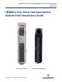
Remote Automation Solutions FB3000 4-Port Serial Communications Module Field Guide d'installation
- Taper
- Guide d'installation

FB3000 4-Port Communications Module Field Installation Guide
D301939X012
November 2023
Energy and Transportation Solutions
FB3000 4-Port Serial Communications
Module Field Installation Guide
3SERL4 Logic Module
3SRSG4 Personality Module

FB3000 4-Port Communications Module Field Installation Guide
D301939X012
November 2023
ii
Application & Device Safety Considerations
Reading these Instructions
Before operating a device or application, read these instructions carefully and understand their safety implications. In some
situations, improper use may result in damage or injury. Keep this manual in a convenient location for future reference. Note
that these instructions may not cover all details or variations in equipment or cover every possible situation regarding
installation, operation, or maintenance. Should problems arise that are not covered sufficiently in the text, immediately contact
Energy and Transportation Solutions (ETS) Customer Support for further information.
Protecting Operating Processes
The failure of a device or application – for whatever reason – may leave an operating process without appropriate protection and
could result in possible damage to property or injury to persons. To protect against this, review the need for additional backup
equipment or provide alternate means of protection (such as alarm devices, output limiting, fail-safe valves, relief valves,
emergency shutoffs, emergency switches, etc.). Contact ETS for additional information.
Using Qualified Personnel
Installation, configuration, and any subsequent modifications to a device or application should only be performed by qualified,
suitably trained personnel information.
System Training
A well-trained workforce is critical to the success of your operation. Knowing how to correctly install, configure, program,
calibrate, and troubleshoot your Emerson equipment provides your engineers and technicians with the skills and confidence to
optimize your investment. ETS offers a variety of ways for your personnel to acquire essential system expertise. Our full-time
professional instructors can conduct classroom training at several of our corporate offices, at your site, or even at your regional
Emerson office. You can also receive the same quality training via our live, interactive Emerson Virtual Classroom and save on
travel costs. For our complete schedule and further information, contact the ETS Training Department at 800-338-8158 or email
us at [email protected].
Grounding Equipment
Ground metal enclosures and exposed metal parts of electrical instruments in accordance with relevant safety standards. For the
USA, refer to OSHA rules and regulations as specified in Design Safety Standards for Electrical Systems, 29 CFR, Part 1910, Subpart S,
dated: May 16, 1981 (OSHA rulings are in agreement with the National Electrical Code). For international locations, refer to IEC
60364-4-41: PROTECTION AGAINST ELECTRIC SHOCK. You must also ground mechanical or pneumatic instruments that include
electrically operated devices such as lights, switches, relays, alarms, or chart drives. The chassis (or earth ground) lug provides a
safe connection point to a customer-designated ground location for ESD and transient voltage suppression. Do not use the
chassis ground lug for signal, common, or return connections. Do not connect the chassis ground lug directly to a lightning
arrestor/lightning rod. Do not run signal wiring in conduit or open trays with power wiring or near heavy electrical equipment.
If shielded wiring is used, ground the shield of the signal wiring at any one point of the signal loop.
Important: Complying with the codes and regulations of authorities having jurisdiction is essential to ensuring personnel safety.
The guidelines and recommendations in this manual are intended to meet or exceed applicable codes and regulations. If
differences occur between this manual and the codes and regulations of authorities having jurisdiction, those codes and
regulations must take precedence.
Protecting from Electrostatic Discharge (ESD)
Any device contains sensitive electronic components which can be damaged by exposure to an ESD voltage. Depending on the
magnitude and duration of the ESD, it can result in erratic operation or complete failure of the equipment. Ensure that you
correctly care for and handle ESD-sensitive components.
Ethernet Connectivity
This automation device is intended to be used in an Ethernet network which does not have public access. The inclusion of this
device in a publicly accessible Ethernet-based network is not recommended.
Returning Equipment
If you need to return any equipment to ETS, it is your responsibility to ensure that the equipment has been cleaned to safe levels,
as defined and/or determined by applicable federal, state and/or local law regulations or codes. You also agree to indemnify ETS
and hold ETS harmless from any liability or damage which ETS may incur or suffer due to your failure to ensure device
cleanliness.

FB3000 4-port Serial Communications Module Field Installation Guide
D301939X012
November 2023
1
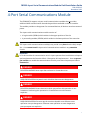
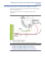
4-Port Serial Communications Module
The FB3000 RTU supports a 4-port serial communications module that to provides
additional MVS communication channels beyond those available on the CPU module.
The module provides no loop power for connected devices; all devices must have external
power.
The 4-port serial communications module consists of:
A logic module (3SERL4) which resides in the upper position of the slot.
A personality module (3SRSG4) which resides in the lower position of the same slot.
Important
The 4-port serial communications module(s) may reside in any base chassis slot(s) except
slot 1. You cannot install a 4-port serial communications module in any extension
chassis.
Important
Le ou les modules de communication série à 4 ports peuvent être installés dans n’importe
quel emplacement de fente du châssis à l’exception de l’emplacement 1. Vous ne pouvez
pas installer un module de communication série à 4 ports dans n’importe quel châssis
d'extension.
DANGER
EXPLOSION HAZARD: Never open the enclosure in a hazardous area.
DANGER
RISQUE D’EXPLOSION: Ne jamais ouvrir le boîtier dans une zone dangereuse.
DANGER
EXPLOSION HAZARD: Ensure the area in which you perform this operation is non-
hazardous. Performing this operation in a hazardous area could cause an
explosion.
DANGER
RISQUE D’EXPLOSION: S’assurer que la zone dans laquelle vous effectuez cette
opération n’est pas dangereuse. Effectuer cette opération en zone dangereuse
peut provoquer une explosion.

FB3000 4-port Serial Communications Module Field Installation Guide
D301939X012
November 2023
2
DANGER
During removal/replacement, (“hot swapping”), switch communications to
whatever manual/backup system you have in place.
DANGER
Lors d'un « remplacement à chaud », mettez en place un système manuel ou de
secours pour assurer la continuité des communications.
Note
This guide describes configuration for the 4-port Serial Communications Module. For
information on hardware and software configuration for the 4088B transmitter or other
devices connected to the port(s), consult the documentation accompanying that device.
Insert the logic module (3SERL4) in any base chassis slot (except slot 1) and insert its
corresponding personality module (3SRSG4) below it.

FB3000 4-port Serial Communications Module Field Installation Guide
D301939X012
November 2023
3
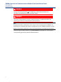
Removing/Replacing the 3SERL4 Logic Module
DANGER
EXPLOSION HAZARD: Never open the enclosure in a hazardous area.
DANGER
RISQUE D’EXPLOSION: Ne jamais ouvrir le boîtier dans une zone dangereuse.
DANGER
EXPLOSION HAZARD: Ensure the area in which you perform this operation is non-
hazardous. Performing this operation in a hazardous area could cause an
explosion.
DANGER
RISQUE D’EXPLOSION: S’assurer que la zone dans laquelle vous effectuez cette
opération n’est pas dangereuse. Effectuer cette opération en zone dangereuse
peut provoquer une explosion.
Notes
You can remove/replace (“hot swap”) the 3SERL4 logic module without removing
power.
If you replace a 3SERL4 module with a new 3SERL4 module, upon insertion, the new
3SERL4 module uses the configuration of the module it replaced.
If you replace a logic module with the logic module of a different module (for
example, replace the logic module of a 12-channel Mixed I/O module with the logic
module of a 4-port Communications module), FBxConnect reports a mismatch. You
must use FBxConnect to correctly re-configure the module type.
If you have an empty slot that has no modules defined, on insertion the new module
assumes factory defaults and you must configure it in FBxConnect.

FB3000 4-port Serial Communications Module Field Installation Guide
D301939X012
November 2023
4
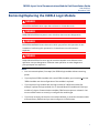
1. Depress the orange tabs at the top and bottom of the 3SERL4 logic module to release
the module and slide it straight out of the slot.
Removing the Logic Module
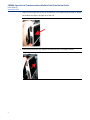
2. Press the replacement logic module into the slot until it is properly seated.
Replacing the Logic Module

FB3000 4-port Serial Communications Module Field Installation Guide
D301939X012
November 2023
5
Removing/Replacing the 3SRSG4 Personality Module
DANGER
EXPLOSION HAZARD: Never open the enclosure in a hazardous area.
DANGER
RISQUE D’EXPLOSION: Ne jamais ouvrir le boîtier dans une zone dangereuse.
DANGER
EXPLOSION HAZARD: Ensure the area in which you perform this operation is non-
hazardous. Performing this operation in a hazardous area could cause an
explosion.
DANGER
RISQUE D’EXPLOSION: S’assurer que la zone dans laquelle vous effectuez cette
opération n’est pas dangereuse. Effectuer cette opération en zone dangereuse
peut provoquer une explosion.
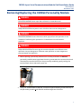
1. When replacing a personality module that is already wired with an identical
personality module (same type) leave the wiring connected to the terminal block and
disconnect the terminal block from the personality module by gently rocking the
terminal block side-to-side until it pops out.
Detaching the Terminal Block with Wires Still Attached
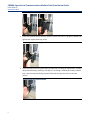
2. Using a ¼” slotted blade screwdriver, loosen the captive fastening screw at the top of
the personality module, and slide the module straight out of the slot.

FB3000 4-port Serial Communications Module Field Installation Guide
D301939X012
November 2023
6
Removing a Personality Module
3. Press the replacement personality module into the slot until it is properly seated, then
tighten the captive fastening screw.
Replacing the Personality Module
4. If you replaced an existing personality module with an identical replacement, reattach
the terminal block by pressing it into place. If installing a 3SRSG4 personality module
into a slot that was previously unused, follow the wiring instructions in the next
section.
Reattaching the Terminal Block

FB3000 4-port Serial Communications Module Field Installation Guide
D301939X012
November 2023
7
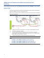
Wiring the 3SRSG4 Personality Module
DANGER
EXPLOSION HAZARD: Never open the enclosure in a hazardous area.
DANGER
RISQUE D’EXPLOSION: Ne jamais ouvrir le boîtier dans une zone dangereuse.
DANGER
EXPLOSION HAZARD: Ensure the area in which you perform this operation is non-
hazardous. Performing this operation in a hazardous area could cause an
explosion.
DANGER
RISQUE D’EXPLOSION: S’assurer que la zone dans laquelle vous effectuez cette
opération n’est pas dangereuse. Effectuer cette opération en zone dangereuse
peut provoquer une explosion.
COM Terminal Blocks
Port
Pin
RS-232
4-wire RS-485
2-wire RS-485
COM1
1
TxD1
TxD1+
TxRxD1+
2
RTS1
TxD1-
TxRxD1-
3
RxD1
RxD1+
X
4
CTS1
RxD1-
X
5
GND1
GND1
GND1
COM2
6
TxD2
TxD2+
TxRxD2+
7
RTS2
TxD2-
TxRxD2-
8
RxD2
RxD2+
X
9
CTS2
RxD2-
X
10
GND2
GND2
GND2
COM3
11
TxD3
TxD3+
TxRxD3+
12
RTS3
TxD3-
TxRxD3-
13
RxD3
RxD3+
X
14
CTS3
RxD3-
X
15
GND3
GND3
GND3

FB3000 4-port Serial Communications Module Field Installation Guide
D301939X012
November 2023
8
Port
Pin
RS-232
4-wire RS-485
2-wire RS-485
COM4
16
TxD4
TxD4+
TxRxD4+
17
RTS4
TxD4-
TxRxD4-
18
RxD4
RxD4+
X
19
CTS4
RxD4-
X
20
GND4
GND4
GND4
X = N/C
Use FBxConnect software to choose the port usage for each of the four COM ports on the
4-port Communications module.
Note
Older standards refer to RS-485 (4-wire) as RS-422.
Connecting a serial port to an RS-232 Device
You can wire any of the four serial ports for communication with an RS-232 device.
When connecting a COM port to another device using RS-232, follow this configuration:
COMn Port Configured for RS-232
1
RS-232 port on device
2
Connect cable shields to suitable Instrument Earth connection point
Notes
For COM1, n=1, pin numbers as follows: a=1, b=2, c=3, d=4, e=5
For COM2, n=2, pin numbers as follows: a=6, b=7, c=8, d=9, e=10
For COM3, n=3, pin numbers as follows: a=11, b=12, c=13, d=14, e=15
For COM4, n=4, pin numbers as follows: a=16, b=17, c=18, d=19, e=20

FB3000 4-port Serial Communications Module Field Installation Guide
D301939X012
November 2023
9
Connecting a serial port to an RS-485 (4-wire) Device
You can wire any of the four serial ports for communication with an RS-485 (4-wire)
device.
When connecting a COM port to another device using RS-485 (4-wire), follow this
configuration:
COMn Configured for RS-485 (4-wire)
1
RS-485 (4-wire) port on device
2
Connect cable shields to suitable Instrument Earth connection point
Notes
For COM1, n=1, pin numbers as follows: a=1, b=2, c=3, d=4, e=5
For COM2, n=2, pin numbers as follows: a=6, b=7, c=8, d=9, e=10
For COM3, n=3, pin numbers as follows: a=11, b=12, c=13, d=14, e=15
For COM4, n=4, pin numbers as follows: a=16, b=17, c=18, d=19, e=20

FB3000 4-port Serial Communications Module Field Installation Guide
D301939X012
November 2023
10
Connecting a serial port to an RS-485 (2-wire) Device
You can wire any of the four serial ports for communication with an RS-485 (2-wire)
device.
When connecting a COM port to another device using RS-485 (2-wire), follow this
configuration:
COMn Configured for RS-485 (2-wire)
1
RS-485 (2-wire) port on device
2
Connect cable shields to suitable Instrument Earth connection point
Notes
For COM1, n=1, pin numbers as follows: a=1, b=2, c=3, d=4, e=5
For COM2, n=2, pin numbers as follows: a=6, b=7, c=8, d=9, e=10
For COM3, n=3, pin numbers as follows: a=11, b=12, c=13, d=14, e=15
For COM4, n=4, pin numbers as follows: a=16, b=17, c=18, d=19, e=20

FB3000 4-port Serial Communications Module Field Installation Guide
D301939X012
November 2023
11
Connecting a serial port to a Rosemount 4088B Transmitter
You can wire any of the four serial ports for communication with a Rosemount 4088B
transmitter using RS-485 (2-wire).
When connecting a COM port to a Rosemount 4088B transmitter follow this
configuration:
COMn RS-485 (2-wire) Connection to a Single Rosemount 4088B Transmitter
1
Enable AC termination using switches
2
RS-485 bus; twisted pair required
3
Connect cable shields to suitable Instrument Earth connection point
Notes
For COM1, n=1, pin numbers as follows: a=1, b=2, c=3, d=4, e=5
For COM2, n=2, pin numbers as follows: a=6, b=7, c=8, d=9, e=10
For COM3, n=3, pin numbers as follows: a=11, b=12, c=13, d=14, e=15
For COM4, n=4, pin numbers as follows: a=16, b=17, c=18, d=19, e=20

FB3000 4-port Serial Communications Module Field Installation Guide
D301939X012
November 2023
12
Connecting a serial port to Multiple Rosemount 4088B Transmitter
(Multi-Drop)
You can wire any of the four serial ports for communication with multiple multi-dropped
Rosemount 4088B transmitters using RS-485 (2-wire).
When wiring to multiple Rosemount 4088B transmitters (multi-drop) using 2-wire RS-485,
follow this configuration:
COMn RS-485 (2-wire) Connection to Multiple 4088B Transmitters (Multi-drop)
1
Enable AC termination using switches on last multi-dropped 4088B transmitter
2
RS-485 bus; twisted pair required
3
Up to ten 4088B transmitters allowed per port. All transmitters require an
external power supply. When communicating with more than six 4088Bs at 9600
baud, update times exceed once a second.
4
Connect cable shields to suitable Instrument Earth connection point
Notes
For COM1, n=1, pin numbers as follows: a=1, b=2, c=3, d=4, e=5
For COM2, n=2, pin numbers as follows: a=6, b=7, c=8, d=9, e=10
For COM3, n=3, pin numbers as follows: a=11, b=12, c=13, d=14, e=15
For COM4, n=4, pin numbers as follows: a=16, b=17, c=18, d=19, e=20

FB3000 4-port Serial Communications Module Field Installation Guide
D301939X012
November 2023
13
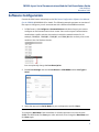
Software Configuration
Consult the FBxConnect online help or the FBxConnect Configuration Software User Manual
(for the FB3000) (D301882X012) for details. The following example presents an overview of
the steps to configure a port to communicate with a Rosemount 4088B transmitter.
1. In FBxConnect, click Configure > Communications and select the port you want to
configure on the Communication Ports screen. Ports on the 4-port Communication
module have a prefix with the slot number in which the module resides. So, for
example, COMM_81, COMM_82, COMM_83, and COMM_84 refer to the 4 ports on the
module in slot 8 of the base chassis.
You can optionally change the Port Description.
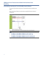
2. Enable Port Settings and set the Port Owner as MVS4088B and the Port Type as
Serial.
3. Select the appropriate Serial Mode for your configuration and click Save.
Note
To change the Baud Rate from the default of 19.2Kb (required in this case since the
4088B uses 9600 baud) first Save your other selections, then change the Baud Rate and
click Save again.

FB3000 4-Port Serial Communications Module Field Installation Guide
D301939X012
November 2023
For customer service and technical support,
visit Emerson.com/SupportNet.
North America and Latin America:
Emerson Automation Solutions
Energy and Transportation Solutions
6005 Rogerdale Road
Houston, TX 77072 U.S.A.
T +1 281 879 2699 | F +1 281 988 4445
Emerson.com/SCADAforEnergy
© 2023 Bristol Inc., an affiliate of Emerson Electric Co. All rights reserved.
This publication is for informational purposes only. While every effort has been
made to ensure accuracy, this publication shall not be read to include any
warranty or guarantee, express or implied, including as regards the products or
services described or their use or applicability. Bristol Inc. (hereinafter “Energy
and Transportation Solutions” or ETS) reserves the right to modify or improve
the designs or specifications of its products at any time without notice. All sales
are governed by ETS terms and conditions which are available upon request. ETS
accepts no responsibility for proper selection, use or maintenance of any
product, which remains solely with the purchaser and/or end-user. Emerson
Automation Solutions, Emerson, and the Emerson logo are trademarks and
service marks of Emerson Electric Co. All other marks are the property of their
respective owners.
United Kingdom:
Emerson Automation Solutions
Meridian East
Meridian Business Park 7
Leicester LE19 1UX UK
T +44 0 870 240 1978
F +44 0 870 240 4389
Europe:
Emerson S.R.L
Regulatory Compliance Shared Services
Department
Company No. J12/88/2006
Emerson 4 Street
Parcul Industrial Tetarom 11
Romania
T +40 374 132 000
Middle East/Africa:
Emerson Automation Solutions
Energy and Transportation Solutions
Emerson FZE
P.O. Box 17033
Jebel Ali Free Zone – South 2
Dubai U.A.E.
T +971 4 8118100 | F +971 4 8865465
Asia-Pacific:
Emerson Automation Solutions
Energy and Transportation Solutions
1 Pandan Crescent
Singapore 128461
T +65 6777 8211| F +65 6777 0947
Energy and Transportation Solutions
-
 1
1
-
 2
2
-
 3
3
-
 4
4
-
 5
5
-
 6
6
-
 7
7
-
 8
8
-
 9
9
-
 10
10
-
 11
11
-
 12
12
-
 13
13
-
 14
14
-
 15
15
-
 16
16


Remote Automation Solutions FB3000 4-Port Serial Communications Module Field Guide d'installation
- Taper
- Guide d'installation
dans d''autres langues
Autres documents
-
Mettler Toledo IND570 Guide d'installation
-
-
Adlink MVP-5200 Series Le manuel du propriétaire
-
Schneider Electric PowerLogic ION8650 Instruction Sheet
-
-
 Allen-Bradley Micro800 Installation Instructions Manual
-
Eurotech DynaGATE 20-30 Le manuel du propriétaire
-
Mitsubishi Electric MI2012-W Manuel utilisateur
-
Aplex APC-3595R Manuel utilisateur
