Schneider Electric PowerLogic ION8650 Instruction Sheet
- Taper
- Instruction Sheet

PowerLogic™ ION8650
Energy and power quality switchboard meter
Medidor de tablero de distribución de energía y de calidad
de energía
Compteur de tableau pour mesure de la qualité de l’énergie
Installation guide
Manual de instalación
Manuel d’installation
7ML02-0305-03
10/2021


ENGLISH
ESPAÑOLFRANÇAIS
English
Español
Français
Safety information ........................................................................................ 5
Overview ........................................................................................................ 9
Installation ................................................................................................... 14
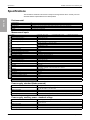
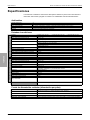
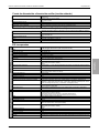
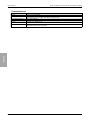
Specifications .............................................................................................. 28
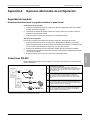
Appendix A: Additional setup options ...................................................... 30
Información de seguridad .......................................................................... 35
Descripción general .................................................................................... 39
Instalación ................................................................................................... 45
Especificaciones ......................................................................................... 62
Appendix A: Opciones adicionales de configuración ............................. 65
Informations de sécurité ............................................................................ 71
Général ......................................................................................................... 75
Installation ................................................................................................... 79
Spécifications .............................................................................................. 96
Appendix A: Options de configuration supplémentaires ....................... 98


© 2021 Schneider Electric. All rights reserved. 5
ENGLISH
Safety information
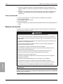
Important information
Read these instructions carefully and look at the equipment to become familiar with
the device before trying to install, operate, service or maintain it. The following
special messages may appear throughout this manual or on the equipment to warn
of potential hazards or to call attention to information that clarifies or simplifies a
procedure.
Please note
Electrical equipment should be installed, operated, serviced and maintained only by qualified
personnel. No responsibility is assumed by Schneider Electric for any consequences arising out of
the use of this material.
A qualified person is one who has the skills and knowledge related to the construction, installation
and operation of electrical equipment and has received safety training to recognize and avoid the
hazards involved.
The addition of either symbol to a “Danger” or “Warning” safety label indicates that an
electrical hazard exists which will result in personal injury if the instructions are not
followed.
This is the safety alert symbol. It is used to alert you to potential personal injury hazards.
Obey all safety messages that follow this symbol to avoid possible injury or death.
DANGER indicates a hazardous situation which, if not avoided, will result in death or
serious injury.
WARNING indicates a hazardous situation which, if not avoided, could result in death
or serious injury.
CAUTION indicates a hazardous situation which, if not avoided, could result in minor
or moderate injury.
CAUTION
NOTICE
NOTICE is used to address practices not related to physical injury.

6© 2021 Schneider Electric. All rights reserved.
ENGLISH
Notices
Legal information
The Schneider Electric brand and any registered trademarks of Schneider Electric Industries SAS
referred to in this guide are the sole property of Schneider Electric SA and its subsidiaries. They may
not be used for any purpose without the owner's permission, given in writing. This guide and its
content are protected, within the meaning of the French intellectual property code (Code de la
propriété intellectuelle français, referred to hereafter as "the Code"), under the laws of copyright
covering texts, drawings and models, as well as by trademark law. You agree not to reproduce, other
than for your own personal, noncommercial use as defined in the Code, all or part of this guide on
any medium whatsoever without Schneider Electric’s permission, given in writing. You also agree not
to establish any hypertext links to this guide or its content. Schneider Electric does not grant any right
or license for the personal and noncommercial use of the guide or its content, except for a non-
exclusive license to consult it on an "as is" basis, at your own risk. All other rights are reserved.
Electrical equipment should be installed, operated, serviced and maintained only by qualified
personnel. No responsibility is assumed by Schneider Electric for any consequences arising out of
the use of this material.
As standards, specifications and designs change from time to time, please ask for confirmation of the
information given in this publication.
FCC Part 15 notice
This equipment has been tested and found to comply with the limits for a Class B digital device,
pursuant to part 15 of the FCC Rules. These limits are designed to provide reasonable protection
against harmful interference in a residential installation. This equipment generates, uses, and can
radiate radio frequency energy, and, if not installed and used in accordance with the instructions, may
cause harmful interference to radio communications. However, there is no guarantee that
interference will not occur in a particular installation. If this equipment does cause harmful
interference to radio or television reception, which can be determined by turning the equipment off
and on, the user is encourages to try to correct the interference by one or more of the following
measures:
Reorient or relocate the receiving antenna.
Increase the separation between the equipment and receiver.
Connect the equipment to an outlet on a circuit different from that to which the receiver is
connected.
Consult the dealer or an experienced radio/TV technician for help.
The user is cautioned that any changes or modifications not expressly approved by Schneider Electric
could void the user’s authority to operate the equipment.
CAN ICES-3(B) /NMB-3(B)
FCC Part 68 notice
This equipment complies with Part 68 of the FCC rules and the requirements adopted by the
Administrative Council for Terminal Attachments (ACTA). On the side of this equipment is a label that
contains, among other information, a product identifier in the format US: AAAEQ##TXXXX. If
requested, this number must be provided to the telephone company.
This equipment uses the following Universal Service Order Codes (“USOC”) jacks: RJ11.
A plug and jack used to connect this equipment to the premises wiring and telephone network must
comply with the applicable FCC Part 68 rules and requirements adopted by the ACTA. A compliant
telephone cord and modular plug or compliant modular jack is provided with this product.

© 2021 Schneider Electric. All rights reserved. 7
ENGLISH
The REN is used to determine the number of devices that may be connected to a telephone line.
Excessive RENs on a telephone line may result in the devices not ringing in response to an incoming
call. In most but not all areas, the sum of RENs should not exceed five (5.0). To be certain of the
number of devices that may be connected to a line, as determined by the total RENs, contact the local
telephone company. The REN for this product is part of the product identifier that has the format US:
AAAEQ##TXXXX. The digits represented by ## are the REN without a decimal point (e.g., 03 is a
REN of 0.3).
If this equipment, Digital Power Meter with Internal Modem, causes harm to the telephone network,
the telephone company will notify you in advance that service may be temporarily discontinued. When
advance notice is not practical, the telephone company will notify you as soon as possible. You will
also be advised of your right to file a complaint with the FCC if you believe it is necessary.
The telephone company may make changes in its facilities, equipment, operations or procedures that
could affect the operation of this equipment. If this happens, the telephone company will provide
advance notice in order for you to make necessary modifications to maintain uninterrupted service.
If you experience trouble with this equipment, Digital Power Meter with Internal Modem, please
contact Schneider Electric at 615-287-3400. If this equipment is causing harm to the telephone
network, the telephone company may request that you disconnect this equipment until the problem
is resolved.
There are no user serviceable parts in this equipment.
Connection to party line service is subject to state tariffs. Contact the state public utility commission,
public service commission or corporation commission for information.
If your premises has specially wired alarm equipment connected to the telephone line, ensure that
the installation of this Digital Power Meter with Internal Modem does not disable your alarm
equipment. If you have questions about what will disable alarm equipment, consult your telephone
company or a qualified installer.
Network compatibility notice for the internal modem
The internal modem in meters equipped with this option is compatible with the telephone systems of
most countries in the world, with the exception of Australia and New Zealand. Use in some countries
may require modification of the internal modem’s initialization strings. If problems using the modem
on your phone system occur, please contact Schneider Electric Technical Support.
Calibration compliance
Schneider Electric certifies that this product meets the published specifications and has been
calibrated and tested using equipment and standards traceable to the National Institute of Standards
and Technology (NIST) in the US or the National Research Council of Canada (NRC). For details,
refer to the Certificate of Calibration for this product.
Standards compliance
Made by Power Measurement Ltd.
N998

8© 2021 Schneider Electric. All rights reserved.
ENGLISH

© 2021 Schneider Electric. All rights reserved. 9
ION8650 switchboard meter installation guide Overview
ENGLISH
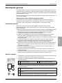
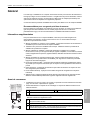
Overview
The PowerLogic™ ION8650 advanced power and energy revenue meter features comprehensive
logging, advanced power quality measurement, multi-protocol and multi-port communications,
including IRIG-B support, and optional onboard and remote I/O capabilities.
This document outlines the steps for installing the FT-21 switchboard version of the ION8650 meter.
High accuracy metering considerations
In situations where the magnitude and quality of the voltage input source is insufficient (e.g.,
installations using PTs with low VA ratings or long conductor runs), consider using an auxiliary-
powered ION8650.
Additional information
For more information on the ION8650 meter, including documentation downloads and software
tools, visit www.se.com. Available technical documentation includes:
ION8650 socket meter installation guide - contains wiring and installation instructions for the socket
version of the ION8650 meter.
ION8650 accuracy verification technical note - details requirements and procedures for validating
the meter’s accuracy.
ION8650 user guide - contains detailed information on meter operation, meter firmware updates,
software support, communications, inputs/outputs, logging, time-of-use, alarm notification, and
other advanced features.
I/O Expander installation guide - describes the optional external I/O device that you can connect to
the ION8650, for additional digital I/O and analog output ports.
Product option documents - provide option-specific information about the various product options
you can order for the meter. They usually ship with the product.
Technical notes - provide instructions for using meter features and for creating custom
configurations.
Online ION Setup help - describes how to use the ION Setup meter configuration software.
ION Reference - explains the ION architecture and describes the operation and behavior of the
different ION modules available in ION hardware and ION software products.
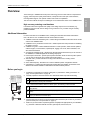
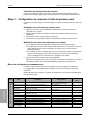
Before you begin
1. Familiarize yourself with the contents of this guide, in particular the “Safety precautions” on
page 10 and “Specifications” on page 28.
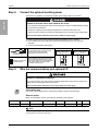
2. Carefully unpack the meter from the box. The switchboard meter ships with the following:
3. Check that the part number on the front nameplate label matches the part number on your sales or
purchase order (see “Front panel label” on page 11):
4. Make sure you have all other required equipment and peripherals appropriate for your installation,
e.g., Ethernet or RS-232 to RS-485 converter, optical probe, revenue seal, etc.
A This installation guide B The meter’s calibration certificate
C Terminal screws, mounting nuts and washers
If you ordered the breakout cable form factor option, the following is also included:
DCOM breakout cable: 24-pin female Molex to female DB9 connector (RS-232), two sets of twisted pair
wires (RS-485)
EOptional Ethernet CAT5 female-to-female coupler (only if you ordered the Ethernet communications
option)
FOptional I/O breakout cable: a 16-pin female Molex to 16 bare-ended wires for connecting to I/O devices
(only if you ordered the onboard I/O option)
A
B
C
D
E
F

Overview ION8650 switchboard meter installation guide
10 © 2021 Schneider Electric. All rights reserved.
ENGLISH
Recommended tools
Torque screwdriver with #2 Phillips and nut driver bits
Precision flat tip screwdriver
Wire cutter, stripper and crimper
Small needlenose pliers
ION Setup meter configuration software (download and install latest version from the website)
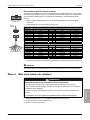
Safety precautions
Installation, wiring, testing and service must be performed in accordance with all local and national
electrical codes.
NOTE
Do not perform Dielectric (Hi-Pot) or Megger testing on the ION8650 because its internal surge protection circuitry
starts functioning at levels below typical Hi-Pot voltages. Contact your local Schneider Electric representative for
more information on device specifications and factory testing.
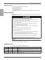
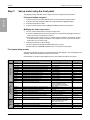
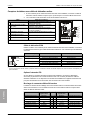
Available models
The ION8650 meter is available in three different models:
HAZARD OF ELECTRIC SHOCK, EXPLOSION, OR ARC FLASH
•Apply appropriate Personal Protective Equipment (PPE) and follow safe electrical work
practices. See NFPA 70E, CSA Z462 or other local standards
•Turn off all power supplying this device and the equipment in which it is installed before
working on or in the equipment.
•Always use a properly rated voltage sensing device to confirm that all power is off.
•Do not exceed the maximum ratings of this device.
•Do not use this device for critical control or protection of persons, animals, property or
equipment.
•Do not short secondary terminals of Voltage Transformer (VT)
•Do not open secondary terminals of Current Transformer (CT)
•Ground secondary circuit of CTs.
•Assume communications and IO wiring are hazardous live until determined otherwise.
•Do not perform Dielectric (Hi-Pot) or Megger testing on this device.
•Connect protective ground (earth) before turning on any power supplying this device.
•Replace all devices, doors and covers before turning on power to this equipment.
Failure to follow these instructions will result in death or serious injury.
Model1Memory Data recorders Description
ION8650A 128 MB 50 (800 channels) Class A power quality analysis meter with 1024 samples/cycle transient detection, Flicker,
PQ waveform support, interharmonics, EN50160 power quality monitoring and Modbus
mastering
ION8650B 64 MB 45 (720 channels) Class S compliant meter with EN50160 power quality monitoring and Modbus mastering
ION8650C 32 MB 5 (80 channels) Basic tariff/energy meter
1 Visit www.se.com for more information on the different models.

© 2021 Schneider Electric. All rights reserved. 11
ION8650 switchboard meter installation guide Overview
ENGLISH
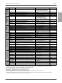
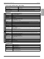
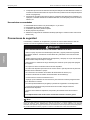
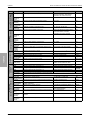
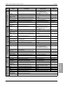
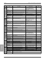
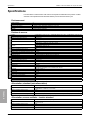
Meter options
The model number (shown in “Front panel label” on page 11) indicates the meter’s options.
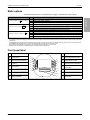
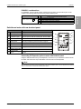
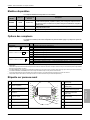
Front panel label
Option Code Description
Power supply1E3-phase power supply (blade powered)2
M 8 6 5 0 A 4 C 0 H 6 C 1 B 0 A H Auxiliary power supply - Standard
JAuxiliary power supply - High voltage
Communications3A0 Front panel infrared optical port, RS-232/RS-485, RS-485
M8650A4C0H6C7A0A C7 Front panel infrared optical port, RS-232/RS-485, RS-485, Ethernet4, internal modem
E1 Front panel infrared optical port, RS-232/RS-485, RS-485, Ethernet4
M1 Front panel infrared optical port, RS-232/RS-485, RS-485, internal modem
I/O5A No digital I/O
M 8 6 5 0 A 4 C 0 H 6 C 1 B 0 A B 4 Form C solid state digital outputs, 3 Form A digital inputs
C 4 Form C solid state digital outputs, 1 Form A solid state digital output, 1 Form A digital input
D Ethernet outage notification
1Refer to “High accuracy metering considerations” on page 9 for recommendations when selecting a power supply option.
2The standard 3-phase power supply is powered from the meter’s voltage measurement connections. Ensure your system meets the meter’s steady state voltage
specifications.
3The ION8650C meter can communicate simultaneously only through a maximum of three ports (the infrared optical port, plus two other communications ports).
The ION8650A and ION8650B meters can communicate simultaneously through all communications ports.
4Some features require Ethernet communications. See “Ethernet option” on page 20 for a list of services.
5Additional inputs and outputs are available through the separately-ordered I/O Expander.
ATest amperage IVoltage transformer ratio (VTR)
BClass accuracy JCurrent transformer ratio (CTR)
CTest constant (LED pulse rate) KPrimary watthour constant
DFrequency LTransformer factor (VTR x CTR)
ECurrent range MMeter internal diagram (view from
front of meter)
FForm factor NANSI bar code
GVoltage input rating OModel number
HWiring configuration PSerial number
8650 METER
*ZYX00123456700000*
XX-1101X001-00 X8650X0X0X6X0X0X
V~
W
FM
CL
Freq
Kt
CA
TA VTR
CTR
PKh
Mult by
E
H
F
G
A
D
B
C
M
P
N
O
I
L
J
K

Overview ION8650 switchboard meter installation guide
12 © 2021 Schneider Electric. All rights reserved.
ENGLISH
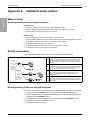
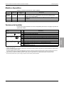
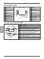
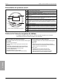
Front panel overview
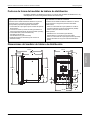
Switchboard meter form factors
The switchboard meter fits in an FT-21 switchboard case cutout and is available in one of the following
switchboard case form factors:
Meter front with cover removed
AWatt pulser: A set of LEDs (infrared, red) used for real energy pulsing.
BVAR pulser: A set of LEDs (infrared, red) used for reactive energy pulsing.
CDemand reset switch: Resets the peak demand values logged in the meter. Can be
activated with the cover on or off.
DRound button (ALT/ENTER): Press to select a highlighted option. Also used to
toggle between NORM and ALT display modes. Press and hold to access Setup
menu.
E
Navigation buttons: Press the up or down buttons to scroll and highlight a different
menu item or to increase/decrease the value of a highlighted number. Press and
hold the up button to move the cursor to the left. Press and hold the down button to
move the cursor to the right.
FInfrared optical port
GMaster reset button: Located in a recessed button under the front label to prevent
accidental activation. You must remove the meter cover and its label to access it.
HTest mode button: Located under the front cover, this places the meter into Test
mode, ceasing accumulation of billable quantities.
IMeter LCD screen
AB
I
D
C
F
G
E
H
Meter case with breakout panel
See “Switchboard meter with rear breakout panel” on page 21 for details.
Rear panel provides:
• 14-pin Molex connector (for the external I/O Expander option)
• Spring-loaded captured wire connectors (for wiring RS-485
communications, IRIG-B and optional onboard I/O)
• DB9 male connector (RS-232 communications)
• RJ45 jack (Ethernet option)
• RJ11 telephone jack (modem option)
• power terminal strip (auxiliary power supply option)
Meter case with breakout cable
See “Switchboard meter with rear breakout cable” on page 22 for details.
Included cables:
• 24-pin Molex connector cable (used with the COM breakout cable for
RS-232 and RS-485 serial communications)
• 2-wire cable for wiring IRIG-B
Optional cables:
• Ethernet cable with RJ45 plug (Ethernet option)
• Telephone cable with RJ11 plug (modem option)
• 16-pin Molex connector cable (onboard I/O option)
• AC power cable (auxiliary power supply option)

© 2021 Schneider Electric. All rights reserved. 13
ION8650 switchboard meter installation guide Overview
ENGLISH
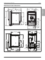
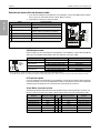
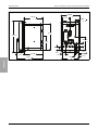
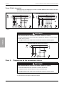
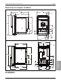
Switchboard meter dimensions
FT-21 switchboard case with breakout panel
FT-21 switchboard case with breakout cable
147 mm (5.8 in)
66 mm
(2.6 in)
248 mm (9.8 in)
189 mm (7.4 in)
226 mm
(8.9 in)
59 mm
(2.3 in)
29 mm
(1.1 in)
14 mm (0.6 in)
28 mm (1.1 in)
41 mm (1.6 in)
113
mm
(4.4 in)
25 mm
(1.0 in)
29 mm
(1.2 in)
164 mm (6.4 in)
286 mm
(10.6 in)
165mm
6.5in
59mm
2.3in
171mm
6.7in
231mm
9.1in
268mm 10.6in
226mm
8.9in
119mm
4.7in
164mm
6.4in
25mm
1.0in
28mm
1.1in
14mm
.6in
41mm
1.6in
147mm
5.8in
29mm
1.1in
113mm
4.4in
29mm
1.1in
74mm
2.9in
29mm
1.2in
165 mm (6.5 in)
286 mm
(10.6 in)
226 mm
(8.9 in)
119 mm
(4.7 in)
171 mm (6.7 in)
231 mm (9.1 in)
59 mm
(2.3 in) 29 mm (1.2 in)
164 mm (6.4 in)
74 mm
(2.9 in)
29 mm
(1.2 in)
25 mm
(1.0 in)
113
mm
(4.4 in)
29
mm
(1.2 in)
14 mm (0.6 in)
28 mm (1.1 in)
41 mm (1.6 in)
147 mm (5.8 in)

Installation ION8650 switchboard meter installation guide
14 © 2021 Schneider Electric. All rights reserved.
ENGLISH
Installation
Installation, wiring, testing and service must be performed in accordance with all local and national
electrical codes.
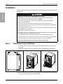
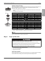
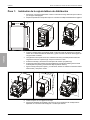
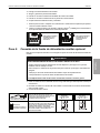
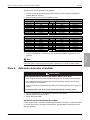
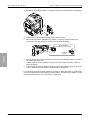
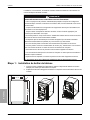
Step 1: Switchboard case installation
1. Disconnect and lock out power. Use a properly rated voltage sensing device to confirm that
power is off.
2. Prepare the mounting surface for the FT-21 case. Refer to the drawing for hole dimensions.
3. Place the meter on a sturdy surface. Locate the thumbscrew (A) at the bottom of the switchboard
cover and turn it counter-clockwise to release the cover.
HAZARD OF ELECTRIC SHOCK, EXPLOSION OR ARC FLASH
•Apply appropriate Personal Protective Equipment (PPE) and follow safe electrical work
practices. See NFPA 70E, CSA Z462 or other local standards.
•Turn off all power supplying this device and the equipment in which it is installed before
working on or in the equipment.
•Always use a properly rated voltage sensing device to confirm that all power is off.
• Never bypass external fusing. Install properly rated fuses in voltage measurement circuits and
in auxiliary (control) power circuit.
• Do not exceed the device’s ratings for maximum limits. Use PTs (potential transformers) or VTs
(voltage transformers) as necessary.
• Never short the secondary of a PT or VT.
• Never open circuit a CT (current transformer); use the shorting block to short circuit the leads of
the CT before removing the connection from the device.
• Connect protective ground (earth) before turning on any power supplying this device.
• All electrical connections to the meter terminals must not be user-accessible after installation.
• Replace all devices, doors and covers before turning on power to this equipment.
Failure to follow these instructions will result in death or serious injury.
141mm [5.6 in]
149mm [5.9 in]
230 mm [9.1 in]
246 mm [9.7 in]
149 mm (5.9 in)
141 mm (5.6 in)
230 mm3 (9.1 in)
246 mm (9.7 in)
4x Ø6.35 mm
(Ø0.25 in)
B
AC
D

© 2021 Schneider Electric. All rights reserved. 15
ION8650 switchboard meter installation guide Installation
ENGLISH
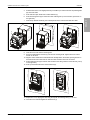
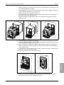
4. Pull the bottom of the cover slightly towards you and lift it up to unhook it from the top retaining tabs
(B). Set cover aside.
5. Push down and open all the lever contact switches (C).
6. Push the locking levers (D) to unlock the meter chassis (push up on the left lever, push down on
the right lever).
7. Grab the top bracket handle (E), then carefully slide out the meter chassis and set it aside.
8. Insert the FT-21 case into the mounting hole.
9. Secure the lockwashers and nuts (F) onto the rear mounting studs. Tighten with a hex socket
wrench or nut driver.
10. Align the meter chassis to the switchboard and carefully slide in the chassis, pushing forward on
the bottom half of the meter bezel to mate the meter and meter case rear connectors.
11. Pull the locking levers (G) to lock the meter chassis to the case (pull down on the left lever, pull up
on the right lever).
12. Push up and close all the lever contact switches (H).
13. Replace the cover, aligning the slots along the top with the retaining tabs (I) on the case.
14. Close the cover and hand-tighten the thumbscrew (J).
E
F
G
H
I
J

Installation ION8650 switchboard meter installation guide
16 © 2021 Schneider Electric. All rights reserved.
ENGLISH
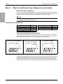
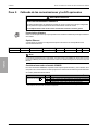
Step 2: Wire the switchboard case voltage and current inputs
Electrical wiring considerations
Install 2 A slow-blow fuses (customer supplied) in the voltage measurement input circuits as shown
in the following electrical wiring diagrams. The auxiliary power supply circuit, if applicable, must also
be fused. See “Step 4: Connect the optional auxiliary power” on page 20 for details.
NOTE
Built-in shorting blocks are provided within the FT-21 drawout case so when the meter is removed, the shorting
blocks automatically short-circuit the current inputs.
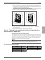
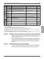
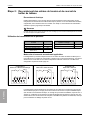
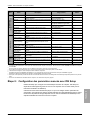
Using Potential Transformers
Volts mode and applicable wiring terminals
The following diagrams show which terminals on the back of the switchboard case are used when
wiring the Form 9, Form 29/Form 36 or Form 35 meter to your electrical system. You must set the
correct volts mode as shown below. See “Front panel setup menus” on page 24.
The following diagrams illustrate typical wiring conventions for the electrical service types supported
by the different ION8650 meter form factors. After completing all electrical wiring, mounting and
installation steps, refer to “Step 10: Use phasor diagrams to verify wiring” on page 26 for details on
meter operation for different systems and volts modes, as well as verification of correct phase wiring.
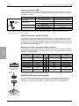
Wye system nominal voltage Requires PT Delta system nominal voltage Requires PT
120 Vac L-N or 208 Vac L-L no up to 480 Vac L-L no
277 Vac L-N or 480 Vac L-L no over 480 Vac L-L yes
347 Vac L-N or 600 Vac L-L yes
over 347 Vac L-N or 600 Vac L-L yes
Form 9
Volts mode = 9S 4-Wire Wye/Delta
Form 29 or Form 36
Volts mode = 29S 4-Wire Wye1
Form 35
Volts mode = 35S 3-Wire
1If you are using the switchboard meter in a Form 36 electrical wiring application, you must set the volts mode to 29S 4-Wire Wye.

© 2021 Schneider Electric. All rights reserved. 17
ION8650 switchboard meter installation guide Installation
ENGLISH
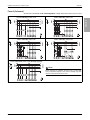
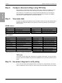
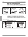
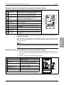
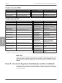
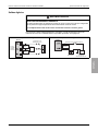
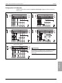
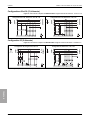
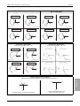
Form 9 (3-element)
Set the meter’s Volts Mode to 9S - 4 Wire Wye/Delta. Voltage measurement limit is 57 to 277 VLN.
Form 9, 4-Wire Wye, no PTs, 3 CTs Form 9, 4-Wire Wye, 3 PTs, 3 CTs
Form 9, 3-Wire Wye, 3 PTs, 3 CTs Form 9, 3-Wire Wye, 3 PTs, 2 CTs
Form 9, 4-Wire Delta, no PTs, 3 CTs (Red/High Leg Delta)
NOTE
Before performing an installation using the Form 9, 4-Wire Delta
wiring configuration (diagram on left), see the Red/High Leg Delta
technical note (download at www.se.com).
B
N
CA
LOAD
LINE
LOAD
LINE
B
N
CA
LOAD
LINE
B
N
CA
LOAD
LINE
B
N
CA
B
C
A
N
LOAD
LINE

Installation ION8650 switchboard meter installation guide
18 © 2021 Schneider Electric. All rights reserved.
ENGLISH
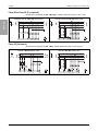
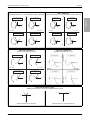
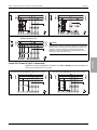
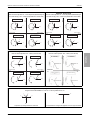
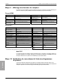
Form 29 or Form 36 (2½-element)
Set the meter’s Volts Mode to 29S - 4 Wire Wye. Voltage measurement limit is 57 to 277 VLN.
Form 35 (2-element)
Set the meter’s Volts Mode to 35S - 3 Wire. Voltage measurement limit is 120 to 480 VLL.
Form 29 or Form 36, 4-Wire Wye, no PTs, 3 CTs Form 29 or Form 36, 4-Wire Wye, 2 PTs, 3 CTs
2A
V1V3Vref I11 I12 I21 I22 I31 I32
A
B
C
N
A
B
C
N
LOAD
LINE
B
N
CA
V1V3Vref I11 I12 I21 I22 I31 I32
A
B
C
N
2A
A
B
C
N
LOAD
LINE
B
N
CA
Form 35, 3-Wire Delta, 2 PTs, 2 CTs Form 35, 4-Wire Wye, 2 PTs, 3 CTs1
1This configuration can affect some of the meter’s parameter calculations. Contact Technical Support for more details.
B
C
A
LOAD
LINE
LOAD
LINE
B
N
CA

© 2021 Schneider Electric. All rights reserved. 19
ION8650 switchboard meter installation guide Installation
ENGLISH
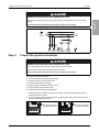
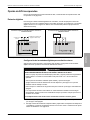
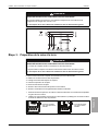
Step 3: Prepare the ground connections
Proper grounding of the meter helps:
Provide a safe path to protective ground (earth)
Protect the electronic circuitry in the meter
Ensure and maintain meter accuracy
Properly operate noise filtering within the meter
Properly operate communications ports
Comply with all local and national regulations
1. Remove any paint, oxidation or other surface coating or contaminants that prevent proper
electrical ground connection.
2. Use a ring or spade connector and 2.08 mm2 (14 AWG) wire to connect the switchboard case
ground to protective ground (earth).
HAZARD OF ELECTRIC SHOCK, EXPLOSION OR ARC FLASH
Do not connect Vref to ground when using the Form 35, 3-Wire Delta, No PTs, 2 CTs wiring
diagram.
Failure to follow these instructions will result in death or serious injury
Form 35, 3-Wire Delta, No PTs, 2 CTs
LOAD
LINE
B
C
A
HAZARD OF ELECTRIC SHOCK, EXPLOSION OR ARC FLASH
• The meter’s ground must be connected to protective ground (earth).
• Do not power up the meter until the ground is connected.
Failure to follow these instructions will result in death or serious injury.
Rear view of switchboard
with breakout panel option Rear view of switchboard
with breakout cable option

Installation ION8650 switchboard meter installation guide
20 © 2021 Schneider Electric. All rights reserved.
ENGLISH
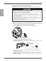
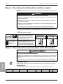
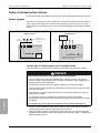
Step 4: Connect the optional auxiliary power
This section only applies if you ordered an auxiliary power supply option for your meter.
Install a properly-rated 3 A slow-blow fuse (customer supplied) on the L/+ terminal.
Do not install a fuse on the meter’s N/- terminal if the power supply source N/- terminal is
grounded.
Connect the G terminal to earth ground.
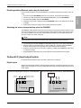
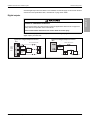
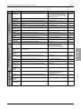
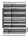
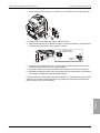
Step 5: Wire the communications and optional I/O
Front optical port
Use an IEC Type II optical probe to communicate using the meter’s front optical port.
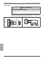
Ethernet option
Below are the default IP service port settings for Ethernet communications.
NOTE
The Ethernet port settings are configurable. See the PowerLogic ION8650 User Guide for more information on
changing Ethernet port number assignments.
HAZARD OF ELECTRIC SHOCK, EXPLOSION OR ARC FLASH
• Turn off all power supplying this device and the equipment in which it is installed before working
on the device or equipment.
• Always use a properly rated voltage sensing device to confirm that all power is off.
• Verify the meter’s power source meets the specifications for your meter’s power supply option.
Failure to follow these instructions will result in death or serious injury.
Auxiliary power cord
on breakout cable
Use the auxiliary power cord (with grounded
U-plug) to connect to properly rated
single-phase AC or DC power source.
Auxiliary power terminal
on breakout panel
Wire the auxiliary power terminal connectors to
properly rated single-phase AC or DC power
source using a wire type and gauge appropriate
for the supply voltage. Use ring or spade
connectors on the wire ends.
Ungrounded AC or DC
power supply source
GLL
Grounded AC or DC
power supply source
GLN
HAZARD OF UNINTENDED OPERATION
Do not use this device for critical control or protection applications where human or equipment
safety relies on the operation of the control circuit.
Failure to follow these instructions can result in death or serious injury.
ION over TCP Modbus RTU EtherGate (COM1) EtherGate (COM4) Modbus TCP DNP over TCP FTP IEC61850
7700 7701 7801 7802 502 20000 21 102
La page est en cours de chargement...
La page est en cours de chargement...
La page est en cours de chargement...
La page est en cours de chargement...
La page est en cours de chargement...
La page est en cours de chargement...
La page est en cours de chargement...
La page est en cours de chargement...
La page est en cours de chargement...
La page est en cours de chargement...
La page est en cours de chargement...
La page est en cours de chargement...
La page est en cours de chargement...
La page est en cours de chargement...
La page est en cours de chargement...
La page est en cours de chargement...
La page est en cours de chargement...
La page est en cours de chargement...
La page est en cours de chargement...
La page est en cours de chargement...
La page est en cours de chargement...
La page est en cours de chargement...
La page est en cours de chargement...
La page est en cours de chargement...
La page est en cours de chargement...
La page est en cours de chargement...
La page est en cours de chargement...
La page est en cours de chargement...
La page est en cours de chargement...
La page est en cours de chargement...
La page est en cours de chargement...
La page est en cours de chargement...
La page est en cours de chargement...
La page est en cours de chargement...
La page est en cours de chargement...
La page est en cours de chargement...
La page est en cours de chargement...
La page est en cours de chargement...
La page est en cours de chargement...
La page est en cours de chargement...
La page est en cours de chargement...
La page est en cours de chargement...
La page est en cours de chargement...
La page est en cours de chargement...
La page est en cours de chargement...
La page est en cours de chargement...
La page est en cours de chargement...
La page est en cours de chargement...
La page est en cours de chargement...
La page est en cours de chargement...
La page est en cours de chargement...
La page est en cours de chargement...
La page est en cours de chargement...
La page est en cours de chargement...
La page est en cours de chargement...
La page est en cours de chargement...
La page est en cours de chargement...
La page est en cours de chargement...
La page est en cours de chargement...
La page est en cours de chargement...
La page est en cours de chargement...
La page est en cours de chargement...
La page est en cours de chargement...
La page est en cours de chargement...
La page est en cours de chargement...
La page est en cours de chargement...
La page est en cours de chargement...
La page est en cours de chargement...
La page est en cours de chargement...
La page est en cours de chargement...
La page est en cours de chargement...
La page est en cours de chargement...
La page est en cours de chargement...
La page est en cours de chargement...
La page est en cours de chargement...
La page est en cours de chargement...
La page est en cours de chargement...
La page est en cours de chargement...
La page est en cours de chargement...
La page est en cours de chargement...
La page est en cours de chargement...
La page est en cours de chargement...
La page est en cours de chargement...
La page est en cours de chargement...
-
 1
1
-
 2
2
-
 3
3
-
 4
4
-
 5
5
-
 6
6
-
 7
7
-
 8
8
-
 9
9
-
 10
10
-
 11
11
-
 12
12
-
 13
13
-
 14
14
-
 15
15
-
 16
16
-
 17
17
-
 18
18
-
 19
19
-
 20
20
-
 21
21
-
 22
22
-
 23
23
-
 24
24
-
 25
25
-
 26
26
-
 27
27
-
 28
28
-
 29
29
-
 30
30
-
 31
31
-
 32
32
-
 33
33
-
 34
34
-
 35
35
-
 36
36
-
 37
37
-
 38
38
-
 39
39
-
 40
40
-
 41
41
-
 42
42
-
 43
43
-
 44
44
-
 45
45
-
 46
46
-
 47
47
-
 48
48
-
 49
49
-
 50
50
-
 51
51
-
 52
52
-
 53
53
-
 54
54
-
 55
55
-
 56
56
-
 57
57
-
 58
58
-
 59
59
-
 60
60
-
 61
61
-
 62
62
-
 63
63
-
 64
64
-
 65
65
-
 66
66
-
 67
67
-
 68
68
-
 69
69
-
 70
70
-
 71
71
-
 72
72
-
 73
73
-
 74
74
-
 75
75
-
 76
76
-
 77
77
-
 78
78
-
 79
79
-
 80
80
-
 81
81
-
 82
82
-
 83
83
-
 84
84
-
 85
85
-
 86
86
-
 87
87
-
 88
88
-
 89
89
-
 90
90
-
 91
91
-
 92
92
-
 93
93
-
 94
94
-
 95
95
-
 96
96
-
 97
97
-
 98
98
-
 99
99
-
 100
100
-
 101
101
-
 102
102
-
 103
103
-
 104
104


Schneider Electric PowerLogic ION8650 Instruction Sheet
- Taper
- Instruction Sheet
dans d''autres langues
Documents connexes
-
Schneider Electric PM5560 Power Meter Manuel utilisateur
-
-
Schneider Electric EVlink Pro AC Instruction Sheet
-
-
-
Schneider Electric ZC Component Heads and Levers Mode d'emploi
Autres documents
-
Square D SQWP141001GY Manuel utilisateur
-
Pass and Seymour PSDS100RC Guide d'installation
-
Gewiss GWD6821 Manuel utilisateur
-
 Stratus ftServer V 2302 Site Planning Manual
-
 Remote Automation Solutions FB3000 4-Port Serial Communications Module Field Guide d'installation
-
Regin IN20020 Mode d'emploi
-
Leviton A8911 High Density Pulse Input Module Manuel utilisateur
-
Comelit 1998V Technical Manual
-
Circutor line-TCPRS1 Mode d'emploi
-

