
A
Обзороборудования
UCE32100T
1
Разъёмпитания
2
Фиксаторразъёмапитания
(пост.тока)
3
ПортобновленияМП
(MicroUSB)
4
Сетевойпорт(RJ-45)
5
Индикаторсоединения
6
Индикаторпитания
7
ГнездопортаUSB2.0Type-B
(хост-компьютер)
B
Установкаоборудования
1
ПодсоединитепортUSBType-BнаUCE32100Tспомощью
кабеляUSB2.0кUSB-портукомпьютера.
2
ПодсоединитеодинконецкабеляEthernet(длинойдо100м)к
портуLinkнаUCE32100T.
3
ПодсоединитедругойконецкабеляEthernetкпортуLinkна
UCE32100R.
4
Подключитеадаптерпитания(изкомплектапоставки)к
источникупеременноготока,азатемподключитевыход
адаптеракразъемупитаниянаUCE32100R.
5
ПодключитедочетырехпериферийныхустройствUSB2.0/3.0к
портамUSBType-AнаUCE32100R.
Фиксациякабелявгнездепитанияпост.тока
Длязакреплениявустройствекабеляадаптерапитания,
используйтенабордляфиксациикабелявгнездепитанияпост.
тока.Доп.информациюсм.вруководствепользователя.
Монтаж
Привинтитемонтажныекронштейныкзаднейчастиустройства
малымивинтамиизмонтажногокомплекта.
Примечание:ЕслиВынеиспользуетеприлагаемыевинты,длина
хвостовика(резьбовойчасти)недолжнапревышать
4,50мм.
Монтажнастене
Привинтитемонтажныекронштейныкстене.
МонтажнаDIN-рейке
1.ПривинтитекронштейныдляDIN-рееккмонтажным
кронштейнамкрупнымивинтамиизмонтажногокомплекта.
2.ПрикрепитеустройствокDIN-рейке.
UCE321004-портовыйUSB2.0-удлинительпокабелюCat5(100м)
www.aten.com
Индикация
UCE32100T
Индикатор
питания
Негорит:питаниенеподключено
Горит:удлинительвключен
Индикатор
соединения
Негорит:соединениенеустановлено
Горит:установленосоединениесприемником
Мигает:передачаданных
UCE32100R
Индикатор
питания
Негорит:питаниенеподключено
Горит:удлинительвключен
Индикатор
соединения
Негорит:соединениенеустановлено
Горит:установленосоединениеспередатчиком
Мигает:передачаданных
UCE32100R
1
Разъёмпитания
2
Фиксаторразъёмапитания
(пост.тока)
3
ПортобновленияМП(MicroUSB)
4
Сетевойпорт(RJ-45)
5
Индикаторсоединения
6
Индикаторпитания
7
ГнездапортовUSB2.0Type-A
(периферийныеUSB-устройства)
A
Revisione Hardware
UCE32100T
1
Connettore d'alimentazione
2
Blocco jack CC
3
Porta aggiornamento fi rmware
(Micro USB)
4
Porta Link (RJ-45)
5
Link LED
6
LED accensione
7
Porta USB 2.0 tipo B femmina
(host)
B
Installazione Hardware
1
Collegare la porta B dell'UCE32100T a una porta USB del computer
tramite cavo USB 2.0.
2
Collegare un'estremità del cavo Ethernet (lunghezza cavo fi no a 100
metri) alla porta di collegamento dell'UCE32100T.
3
Collegare l'altra estremità del cavo Ethernet alla porta di collegamento
dell'UCE32100R.
4
Inserire l'alimentatore (incluso in questa confezione) in una
sorgente CA e collegare l'altra estremità nel jack di alimentazione
dell'UCE32100R.
5
Collegare fi no a quattro periferiche USB 2.0/3.0 alle porte USB di tipo
A dell'UCE32100R.
Protezione del jack CC
Per proteggere l'alimentatore del dispositivo, usare il kit di blocco del jack
CC:
Per ulteriori informazioni fare riferimento il manuale dell’utente.
Montaggio
Avvitare le staffe di montaggio sul retro dell'unità usando le viti più piccole
tra quelle fornite in dotazione con il kit di montaggio.
Nota: se non si utilizzano le viti in dotazione, la lunghezza del gambo (la
parte fi lettata) non deve superare i 4,5 mm.
Montaggio a parete
Avvitare le staffe di montaggio su una parete.
Montaggio della guida DIN
1. Avvitare le staffe della guida DIN sulle staffe di montaggio usando le viti
più grandi tra quelle fornite in dotazione con il kit di montaggio.
2. Appendere l'unità alla guida DIN.
EstensoreCAT5con4porteUSB2.0UCE32100(100m)
www.aten.com
Comportamento LED
UCE32100T
LED
alimentazione
Spento: Nessuna alimentazione
Acceso: l'estensore è alimentato
LED di
collegamento
Spento: Nessun collegamento stabilito
Acceso: Collegamento stabilito con il ricevitore
Lampeggiante: Trasmissione dei dati
UCE32100R
LED
alimentazione
Spento: Nessuna alimentazione
Acceso: l'estensore è alimentato
LED di
collegamento
Spento: Nessun collegamento stabilito
Acceso: Collegamento stabilito con il trasmettitore
Lampeggiante: Trasmissione dei dati
UCE32100R
1
Connettore d'alimentazione
2
Blocco jack CC
3
Porta aggiornamento fi rmware
(Micro USB)
4
Porta Link (RJ-45)
5
Link LED
6
LED accensione
7
Porte USB 2.0 tipo B femmina
(periferiche USB)
A
Revisión del hardware
UCE32100T
1
Conector de alimentación
2
Bloqueo clavija DC
3
Puerto de actualización del
fi rmware (Micro USB)
4
Puerto de conexión (RJ-45)
5
LED de conexión
6
LED de alimentación
7
Puerto USB 2.0 tipo B hembra
(anfi trión)
B
Instalación del hardware
1
Conecte el puerto USB tipo B del UCE32100T a un puerto USB del
ordenador con un cable USB 2.0.
2
Conecte un extremo de un cable Ethernet (longitud del cable de hasta
100 metros) al puerto de conexión (Link) del UCE32100T.
3
Conecte el otro extremo del cable Ethernet al puerto de conexión del
UCE32100R.
4
Enchufe el adaptador de corriente (incluido en el paquete) a una
fuente de CA y enchufe el otro extremo en la clavija de alimentación
(Power) del UCE32100R.
5
Conecte hasta cuatro dispositivos periféricos USB 2.0/3.0 a los puertos
USB tipo A del UCE32100R.
Asegurar la clavija DC
Para fi jar el adaptador de corriente al dispositivo, utilice el kit de bloqueo
de clavija DC:
Para más información, consulte el manual del usuario.
Montaje
Atornille los soportes de montaje en la parte posterior de la unidad con
los tornillos más pequeños incluidos en el kit de montaje.
Nota: Si no utiliza los tornillos incluidos, la longitud del vástago (la parte
roscada) no debe superar los 4,50mm.
Montaje en pared
Atornille los soportes de montaje a la pared.
Montaje en raíl DIN
1. Atornille los soportes del raíl DIN a los soportes de montaje utilizando
los tornillos más grandes incluidos con el kit de montaje.
2. Cuelgue la unidad en el raíl DIN.
ExtensorUCE32100de4puertosUSB2.0CAT5Extender(100m)
www.aten.com
Comportamiento del LED
UCE32100T
LED de
alimentación
Apagado: No hay alimentación
Encendido: El extensor está encendido
LED de
conexión
Apagado: No se ha establecido conexión
Encendido: Conexión establecida con el receptor
Parpadeando: Transmisión de datos
UCE32100R
LED de
alimentación
Apagado: No hay alimentación
Encendido: El extensor está encendido
LED de
conexión
Apagado: No se ha establecido conexión
Encendido: Conexión establecida con el transmisor
Parpadeando: Transmisión de datos
UCE32100R
1
Conector de alimentación
2
Bloqueo clavija DC
3
Puerto de actualización del
fi rmware (Micro USB)
4
Puerto de conexión (RJ-45)
5
LED de conexión
6
LED de alimentación
7
Puertos USB 2.0 tipo A hembra
(periféricos USB)
A
Hardware Übersicht
UCE32100T
1
Netzbuchse
2
DC-Buchse Verriegelung
3
Anschluss für Firmware-
Aktualisierung (Micro USB)
4
Link Port (RJ-45)
5
Link LED
6
Netz-LED
7
USB 2.0 Typ-B Buchse (Host)
B
Hardware Installation
1
Verbinden Sie den USB Typ-B Anschluss des UCE32100T über ein USB
2.0 Kabel mit einem USB-Anschluss am Computer.
2
Verbinden Sie ein Ende eines Ethernet-Kabels (Kabellänge bis zu 100
Meter) mit dem Link Port des UCE32100T.
3
Verbinden Sie das andere Ende des Ethernet-Kabels mit dem Link Port
des UCE32100R.
4
Stecken Sie das Netzteil (im Lieferumfang enthalten) in eine Steckdose
und das andere Ende in die Steckdose des UCE32100R.
5
Schließen Sie bis zu vier USB 2.0/3.0 Peripheriegeräte an die USB Typ-A
Anschlüsse des UCE32100R an.
DC-Buchse sichern
Um das Netzteil am Gerät zu sichern, verwenden Sie das DC-Buchse
Verriegelungskit:
Weitere Informationen fi nden Sie im Benutzerhandbuch.
Montage
Schrauben Sie die Montagehalterungen mit den kleineren Schrauben, die
im Montagesatz enthalten sind, in die Rückseite des Gerätes.
Hinweis: Wenn Sie die mitgelieferten Schrauben nicht verwenden,
darf die Länge des Schaftes (Gewindeteil) 4,50 mm nicht
überschreiten.
Wandmontage
Schrauben Sie die Montagehalterungen an eine Wand.
DIN Schienenmontage
1. Schrauben Sie die DIN Schienenhalterungen mit den größeren
Schrauben, die im Lieferumfang des Montagesatzes enthalten sind, an
die Montagehalterungen.
2. Hängen Sie das Gerät an die DIN Schiene.
UCE321004-PortUSB2.0CAT5Extender(100m)
www.aten.com
LED Verhalten
UCE32100T
Betriebsanzeige-LED
Aus: Kein Strom angeschlossen
Ein: Der Extender wird mit Strom versorgt
Link LED
Aus: Keine Verbindung hergestellt
Ein: Verbindung mit Receiver hergestellt
Blinken: Datenübertragung
UCE32100R
Betriebsanzeige-LED
Aus: Kein Strom angeschlossen
Ein: Der Extender wird mit Strom versorgt
Link LED
Aus: Keine Verbindung hergestellt
Ein: Verbindung mit Transmitter hergestellt
Blinken: Datenübertragung
UCE32100R
1
Netzbuchse
2
DC-Buchse Verriegelung
3
Anschluss für Firmware-
Aktualisierung (Micro USB)
4
Link Port (RJ-45)
5
Link LED
6
Netz-LED
7
USB 2.0 Typ-A Buchsen
(USB Peripheriegeräte)
A
Présentation du matériel
UCE32100T
1
Prise d'alimentation
2
Verrouillage prise CC
3
Port de mise à niveau du
microprogramme (Micro USB)
4
Port Link (Liaison) (RJ-45)
5
LED Link (Liaison)
6
LED d'alimentation
7
Port femelle USB 2.0 type B
(Hôte)
B
Installation matérielle
1
Connectez le port USB type B de l'UCE32100T à un port USB de
l'ordinateur à l'aide d'un câble USB 2.0.
2
Connectez une extrémité d'un câble Ethernet (longueur de câble
jusqu'à 100 mètres) au port Link de l'UCE32100T.
3
Connectez l'autre extrémité du câble Ethernet au port Link de
l'UCE32100R.
4
Branchez l'adaptateur d'alimentation (fourni avec ce paquet) à une
source CA et branchez l'autre extrémité à la prise d'alimentation de
l'UCE32100R.
5
Connectez jusqu'à quatre périphériques USB 2.0/3.0 aux ports USB de
type A de l'UCE32100R.
Sécurisation de la prise CC
Pour fi xer l'adaptateur d'alimentation à l'appareil, utilisez le kit de
verrouillage de prise CC :
Pour plus d'informations, reportez-vous au manuel de l'utilisateur.
Montage
Vissez les supports de montage à l'arrière de l'appareil à l'aide des petites
vis fournies dans le kit de montage.
Remarque : Si vous n'utilisez pas les vis fournies, la longueur de la tige (la
partie fi letée) ne doit pas dépasser 4,50 mm.
Montage mural
Vissez les supports de montage sur un mur.
Montage de rail DIN
1. Vissez les supports de rail DIN aux supports de montage à l'aide des
grandes vis fournies avec le kit de montage.
2. Accrocher l'appareil sur le rail DIN.
RépéteurUSB2.0CAT5à4portsUCE32100(100m)
www.aten.com
Comportement des LED
UCE32100T
LED
d'alimentation
Éteinte : Pas d'alimentation connectée
Allumée : Le répéteur est alimenté
LED Link
(Liaison)
Éteinte : Aucune liaison établie
Allumée : Liaison établie avec le récepteur
Clignotante : Transmission de données
UCE32100R
LED
d'alimentation
Éteinte : Pas d'alimentation connectée
Allumée : Le répéteur est alimenté
LED Link
(Liaison)
Éteinte : Aucune liaison établie
Allumée : Liaison établie avec le transmetteur
Clignotante : Transmission de données
UCE32100R
1
Prise d'alimentation
2
Verrouillage prise CC
3
Port de mise à niveau du
microprogramme (Micro USB)
4
Port Link (Liaison) (RJ-45)
5
LED Link (Liaison)
6
LED d'alimentation
7
Ports femelles USB 2.0 type A
(Périphériques USB)
Wall Mounting DIN Rail Mounting
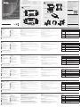
A
Hardware Review
UCE32100T
1
Power Jack
2
DC Jack Lock
3
Firmware Upgrade Port
(Micro USB)
4
Link Port (RJ-45)
5
Link LED
6
Power LED
7
USB 2.0 Type-B Female Port
(Host)
B
Hardware Installation
1
Connect UCE32100T’s USB Type-B Port to a USB port on the computer
using a USB 2.0 cable.
2
Connect one end of an Ethernet cable (cable length up to 100 meters)
to UCE32100T’s Link port.
3
Connect the other end of the Ethernet cable to the UCE32100R’s Link
port.
4
Plug the power adapter (included with this package) into an AC source
and plug the other end into UCE32100R’s Power Jack.
5
Connect up to four USB 2.0/3.0 peripheral devices to UCE32100R’s
USB Type-A ports.
Securing DC Jack
To secure the power adapter to the device, use the DC Jack Lock Kit:
For more information, refer to the user manual.
Mounting
Screw the mounting brackets into the back of the unit using the smaller
screws supplied in the Mounting Kit.
Note: If you do not use the supplied screws, the length of the shank (the
threaded portion) must not exceed 4.50mm.
Wall Mounting
Screw the mounting brackets to a wall.
Din Rail Mounting
1. Screw the DIN rail brackets to the mounting brackets using the larger
screws supplied with the Mounting Kit.
2. Hang the unit on the DIN rail.
B
Hardware Installation
Mounting
Securing DC Jack
© Copyright 2019 ATEN
®
International Co., Ltd.
ATEN and the ATEN logo are trademarks of ATEN International Co., Ltd. All rights reserved. All
other trademarks are the property of their respective owners.
Part No. PAPE-1223-Q80G Printing Date: 05/2019
4-port USB 2.0 CAT 5 Extender (100m)
Quick Start Guide
UCE32100
UCE321004-portUSB2.0CAT5Extender(100m)
www.aten.com
LED Behavior
UCE32100T
Power LED
Off: No power connected
On: The extender is powered
Link LED
Off: No link established
On: Link established with the Receiver
Flash: Data transmission
UCE32100R
Power LED
Off: No power connected
On: The extender is powered
Link LED
Off: No link established
On: Link established with the Transmitter
Flash: Data transmission
Package Contents
1 UCE32100T USB 2.0 CAT 5 Transmitter
1 UCE32100R USB 2.0 CAT 5 Receiver
1 USB 2.0 Type-A Male to Type-B Male Cable
1 Power Adapter
1 Power Cord
4 Mounting Kit
2 Din Rail
2 DC Jack Lock Kit
2 Rubber Feet Sets
1 User Instructions
A
Hardware Review
Support and Documentation Notice
All information, documentation, fi rmware,
software utilities, and specifi cations
contained in this package are subject to
change without prior notifi cation by
the manufacturer.
To reduce the environmental impact of our
products, ATEN documentation and software
can be found online at
http://www.aten.com/download/
Technical Support
www.aten.com/support
이 기기는 업무용(A급) 전자파적합기기로서 판매자 또는
사용자는 이 점을 주의하시기 바라며, 가정외의 지역에
서 사용하는 것을 목적으로 합니다.
Scan for
more information
EMC Information
FEDERAL COMMUNICATIONS COMMISSION INTERFERENCE
STATEMENT:
This equipment has been tested and found to comply with the limits
for a Class A digital device, pursuant to Part 15 of the FCC Rules.
These limits are designed to provide reasonable protection against
harmful interference when the equipment is operated in a commercial
environment. This equipment generates, uses, and can radiate radio
frequency energy and, if not installed and used in accordance with
the instruction manual, may cause harmful interference to radio
communications. Operation of this equipment in a residential area
is likely to cause harmful interference in which case the user will be
required to correct the interference at his own expense.
FCC Caution: Any changes or modifi cations not expressly approved by
the party responsible for compliance could void the user's authority to
operate this equipment.
Warning: Operation of this equipment in a residential environment
could cause radio interference.
This device complies with Part 15 of the FCC Rules. Operation is subject
to the following two conditions: (1) this device may not cause harmful
interference, and (2) this device must accept any interference received,
including interference that may cause undesired operation.
UCE32100R
1
Power Jack
2
DC Jack Lock
3
Firmware Upgrade Port
(Micro USB)
4
Link Port (RJ-45)
5
Link LED
6
Power LED
7
USB 2.0 Type-A Female Ports
(USB peripherals)
4
1
2
3
7
5
6
4
1
2
3
7
5
6
1
5
6
4
2
3
Cat 5/6e Ethernet Cable
UCE32100T
UCE32100R
1
5
6
4
2
3
Cat 5/6e Ethernet Cable
UCE32100T
UCE32100R
UCE32100T
UCE32100R
La page est en cours de chargement...
-
 1
1
-
 2
2


dans d''autres langues
- italiano: ATEN UCE32100 Guida Rapida
- English: ATEN UCE32100 Quick start guide
- español: ATEN UCE32100 Guía de inicio rápido
- Deutsch: ATEN UCE32100 Schnellstartanleitung
- русский: ATEN UCE32100 Инструкция по началу работы
- português: ATEN UCE32100 Guia rápido
- polski: ATEN UCE32100 Skrócona instrukcja obsługi
- 日本語: ATEN UCE32100 クイックスタートガイド
- Türkçe: ATEN UCE32100 Hızlı başlangıç Kılavuzu
Documents connexes
-
ATEN UCE3250 Guide de démarrage rapide
-
ATEN UEH4102 Guide de démarrage rapide
-
ATEN CE924 Guide de démarrage rapide
-
ATEN CE611 Guide de démarrage rapide
-
-
ATEN KE9952 Guide de démarrage rapide
-
ATEN KE6912T Guide de démarrage rapide
-
-
ATEN UEH4002A Guide de démarrage rapide
-
ATEN KE6940AiT Guide de démarrage rapide