ATEN VK258 Guide de démarrage rapide
- Catégorie
- Boîtiers de commutation série
- Taper
- Guide de démarrage rapide

Блок расширения VK258 с 8-ю цифровыми портами ввода/вывода
A
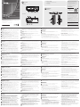
Обзор
Видспереди
1
ИндикаторыI/O:Горит зеленым — осуществляется передача
сигналов между устройством ввода-вывода и контроллером ATEN.
Мигает зеленым — выполняется обновление микропрограммы.
2
ИндикаторLAN:Горит зеленым — VK258 подключен к сети.
3
ИндикаторVKLINK:Горит зеленым — установлено соединение
между VK258 и контроллером ATEN.
4
ИндикаторDCOUTPUTOVERLOAD:Горит оранжевым — превышена
максимально допустимая выходная мощность для выхода DC
OUTPUT. В этом случае следует отключить все устройства, чтобы
понизить выходную мощность, и перезагрузить блок.
5
ПортUSB:Используется для подключения USB-накопителя для
обновления микропрограммы.
6
ИндикаторUSB:Мигает зеленым — выполняется обновление
микропрограммы через USB-устройство. Не горит — обновление
завершено. Горит оранжевым — не удалось выполнить обновление.
7
КнопкаRESET: Нажатие кнопки приводит к сбросу сетевых настроек.
После сброса настроек индикатор LAN погаснет и вновь загорится
7
ПортDCOUTPUT:Обеспечивает подачу 12 В питания с максимальным
суммарным током 300мА к подключенным устройствам ввода-вывода.
B
Установка
Монтажвстойке
1
С помощью прилагаемых винтов прикрепите кронштейны к обеим
сторонам устройства.
2
Привинтите кронштейны к стойке, как показано на рисунке B-2.
Установкаоборудования
1. Для заземления устройства возьмите заземляющий провод и
подсоедините один конец провода к контакту заземления, а другой конец -
к подходящему заземленному объекту.
Примечание: Не пропускайте это действие. Надлежащее заземление
помогает защитить устройство от повреждений, вызванных
перепадами напряжения и статическим электричеством.
2. Подключите до восьми цифровых устройств ввода-вывода с помощью
прилагаемых клеммников.
3. (Дополнительно) Если подключенные устройства ввода-вывода не
имеют собственного источника питания, подключите устройства ввода-
вывода к порту DC OUTPUT с помощью прилагаемого клеммника.
4. С помощью кабеля Ethernet подключите порт LAN на блоке
к коммутатору PoE. При этом блок будет подключен к сети и
одновременно получать питание.
5. (Дополнительно) Для подачи питания через адаптер питания
подключите адаптер питания к разъему питания блока и к источнику
питания переменного тока.
6. С помощью селектора Controller ID задайте ID-номер контроллера
ATEN, к которому подключается блок.
7. С помощью селектора Expander ID присвойте ID-номер блоку расширения.
Конфигурированиепрограммногообеспечения
1. В конфигураторе ATEN (VK6000) откройте файл проекта.
2. Добавьте блок в проект, а затем настройте подключенные устройства
ввода-вывода.
3. Загрузите проект в контроллер. Индикатор VK загорится зеленым,
когда блок подключится к контроллеру.
зеленым. Для перезагрузки блока прижмите кнопку на 8 секунд — после
этого все индикаторы I/O вспыхнут одновременно один раз. Примерно
через 5 секунд все индикаторы I/O загорятся зеленым — показывая,
что выполняется загрузка блока. После выполнения перезагрузки все
индикаторы I/O погаснут.
8
ИндикаторPOWER:Горит зеленым — блок получает питание.
Видсзади
1
ПереключательControllerID:Задает ID-номер контроллера ATEN, к
которому подключается блок.
2
ПереключательExpanderID:Задает собственный ID-номер блока; ID-номер
требуется при настройке блока в конфигураторе ATEN (VK6000).
3
КаналыI/O:Позволяют подключить до восьми устройств ввода-вывода.
• Цифровой вход: вход c программируемым диапазоном 1~24 В (пост.тока)
или с замыканием контактов напряжением +12 В (пост.тока)
• Цифровой выход: сток 300 мА от 24 В (пост.тока)
4
Контактзаземления: Для подсоединения заземляющего провода.
5
Разъёмпитания:Для подключения кабеля от адаптера питания.
6
ПортEthernet:Для подключения кабеля Ethernet.
www.aten.com
Scatola di espansione I/O digitale a 8 canali VK258
A
Revisione Hardware
Vista anteriore
1
LED I/O: Si accende in verde per indicare che sta avvenendo la trasmissione
dei segnali tra il dispositivo I/O e un controller ATEN. Il lampeggio verde indica
che è in corso l'aggiornamento del fi rmware.
2
LED LAN: Si accende in verde quando il VK258 è connesso alla rete.
3
LED di collegamento VK: Si accende in verde quando il VK258 ha stabilito
una connessione con il controller ATEN connesso.
4
LED sovraccarico uscita CC: Si accende in arancione quando l'uscita CC
supera il massimo consentito. In questo caso, scollegare tutti i dispositivi per
ridurre l'uscita di potenza, quindi riavviare l'unità.
5
Porta USB: Riceve un'unità USB per aggiornare il fi rmware.
6
LED USB: Si accende in verde per indicare che è in corso un aggiornamento
del fi rmware tramite un dispositivo USB, e si spegne al termine
dell'aggiornamento. Si accende in arancione per indicare che l'aggiornamento
è riuscito.
7
Pulsante di ripristino: Premere una volta per ripristinare le impostazioni
di rete. Il LED LAN si spegne e lampeggia nuovamente in verde per indicare
7
Porta uscita CC: Fornisce una potenza totale in uscita di massimo 12 VCC/300mA
m ai dispositivi I/O collegati.
B
Installazione
Montaggio in rack
1
Usare le viti in dotazione per fi ssare le staffe su entrambi i lati dell'unità.
2
Avvitare le staffe sul rack, come mostrato nel diagramma B-2.
Confi gurazione hardware
1. Usare un cavo di messa a terra per mettere a terra l'unità collegandone
un'estremità al terminale di messa a terra e l'altra estremità a un oggetto messo a
terra idoneo.
Nota: Non saltare questo passaggio. La messa a terra adeguata aiuta a prevenire
danni all'unità dovuti a sovraccarico o elettricità statica.
2. Collegare fi no a 8 dispositivi I/O digitali usando le morsettiere in dotazione.
3. (Facoltativo) Se i dispositivi I/O collegati non dispongono di alimentazione propria,
collegarli a una porta di uscita CC usando la morsettiera in dotazione.
4. Usare un cavo Ethernet per collegare la porta LAN dell'unità a un interruttore
PoE. In tal modo l'unità viene connessa alla rete e riceve contemporaneamente
l'alimentazione.
5. (Facoltativo) Per fornire l'alimentazione tramite adattatore, inserire l'adattatore
nel connettore dell'unità e a una fonte di alimentazione CA.
6. Usare l'interruttore dell'ID del controller per specifi care l'ID del controller ATEN
al quale si collega l'unità.
7. Usare l'interruttore dell'ID dell'espansore per assegnare un ID all'unità.
Confi gurazione software
1. In ATEN Confi gurator (VK6000), aprire un fi le di progetto.
2. Aggiungere l'unità al progetto e confi gurare i dispositivi I/O installati.
3. Caricare il progetto sul controller. Il LED VK si illumina in verde quando l’unità
si è collegata correttamente al controller.
che le impostazioni sono state ripristinate. Per riavviare l'unità, premere e tenere
premuto il pulsante per 8 secondi, fi nché tutti i LED I/O lampeggiano all'unisono.
In circa 5 secondi, tutti i tutti i LED I/O lampeggiano in verde per indicare che
l'unità si sta riavviando. Il riavvio è completato quando i LED I/O si spengono.
8
LED alimentazione: Si accende in verde per indicare che l'unità è alimentata.
Vista posteriore
1
Interruttore dell'ID del controller: Imposta l'ID del controller ATEN al quale si
connette l'unità.
2
Interruttore dell'ID dell'espansore: Imposta un ID per l'unità; l'ID sarà
necessario per la confi gurazione dell'unità in ATEN Confi gurator (VK6000).
3
Canali I/O: Collegare fi no a otto dispositivi I/O.
• Ingresso digitale: intervallo di ingresso programmabile 1 - 24 VCC o chiusura
contatto con una tensione di pull-up di +12 VCC
• Uscita digitale: dissipazione 300 mA da 24 VCC
4
Terminale di massa: Riceve un cavo di messa a terra.
5
Connettore di alimentazione: Riceve il cavo dell'adattatore di alimentazione.
6
Porta Ethernet: Riceve un cavo Ethernet.
www.aten.com
VK258 Caja de expansión de I/O digital de 8 canales
A
Revisión del hardware
Vista frontal
1
LEDs I/O: Se ilumina en verde para indicar que las señales se están
transmitiendo entre un dispositivo de I/O y un controlador ATEN. Parpadea en
verde para indicar que hay una actualización de fi rmware en curso.
2
LED de la LAN: Se ilumina en verde cuando el VK258 está conectado a la red.
3
LED de conexión del VK: Se ilumina en verde cuando el VK258 ha
establecido una conexión con el controlador ATEN conectado.
4
LED de sobrecarga de salida DC: Se ilumina en naranja cuando la salida
de DC excede la salida máxima permitida. En este caso, desconecte todos los
dispositivos para disminuir la potencia de salida y luego reinicie la unidad.
5
Puerto USB: Recibe una unidad USB para actualizar el fi rmware.
6
LED USB: Se ilumina en verde para indicar que hay una actualización
de fi rmware en curso a través de un dispositivo USB y se apaga cuando
la actualización ha fi nalizado. Se ilumina en naranja para indicar que la
actualización no tuvo éxito.
7
Botón restablecer: Presione una vez para restablecer la confi guración de red.
El LED de la LAN se apaga y se ilumina en verde nuevamente para indicar que
6
Puerto Ethernet: Recibe un cable Ethernet.
7
Puerto de salida DC: Suministra una salida de corriente total de 12 VDC/300mA
máx a los dispositivos de I/O conectados.
B
Instalación
Montaje en rack
1
Utilice los tornillos suministrados para fi jar los soportes a ambos lados de la unidad.
2
Atornille los soportes al bastidor, como se muestra en el diagrama B-2.
Confi guración de hardware
1. Utilice un cable de conexión a tierra para conectar a tierra la unidad conectando
un extremo al terminal de conexión a tierra y el otro extremo a un objeto
correctamente conectado a tierra.
Nota: No omita este paso. La conexión a tierra adecuada ayuda a evitar daños en
la unidad por sobrecargas de energía o electricidad estática.
2. Conecte hasta ocho dispositivos de I/O digitales utilizando los bloques de
terminales suministrados.
3. (Opcional) Si los dispositivos de I/O conectados no tienen su propia fuente
de alimentación, conecte los dispositivos de I/O al puerto de salida de DC
utilizando el bloque de terminales suministrado.
4. Utilice un cable Ethernet para conectar el puerto LAN de la unidad a un
conmutador PoE. Esto conecta la unidad a la red y recibe energía al mismo tiempo.
5. (Opcional) Para suministrar alimentación a través de un adaptador de
alimentación, enchufe un adaptador de alimentación en el conector de
alimentación de la unidad y en una fuente de alimentación de AC.
6. Utilice el interruptor de ID del controlador para especifi car el ID del controlador
ATEN al que se conecta la unidad.
7. Utilice el interruptor de ID del expansor para asignar una ID a la unidad.
Confi guración del software
1. En el Confi gurador ATEN (VK6000), abra un archivo de proyecto.
2. Añada la unidad al proyecto y luego confi gure los dispositivos de I/O
instalados.
3. Suba el proyecto al controlador. El LED del VK se ilumina en verde cuando la
unidad se está correctamente conectada al controlador.
los ajustes han sido restablecidos. Para reiniciar la unidad, mantenga presionado
el botón durante 8 segundos, hasta que todos los LED de I/O se iluminen una vez
al unísono. En aproximadamente 5 segundos, todos los LED de I/O se iluminan en
verde para indicar que la unidad se está iniciando. El reinicio se completa cuando
los LEDs de I/O se apagan.
8
LED de alimentación: Se ilumina en verde para indicar que la unidad está
recibiendo alimentación.
Vista posterior
1
Interruptor de ID del controlador: Establece el ID del controlador ATEN al que
se conecta la unidad.
2
Interruptor de ID del expansor: Establece una ID para la unidad; la ID será
necesaria al confi gurar la unidad en el Confi gurador ATEN (VK6000).
3
Canales de I/O: Conecte hasta ocho dispositivos I/O.
• Entrada digital: rango de entrada programable 1 - 24VDC o carcasa de contacto
con pull-up de +12 VDC
• Salida digital: Disipador de 300mA de 24 VDC
4
Terminal de conexión a tierra: Recibe un cable de tierra.
5
Conector de alimentación: Recibe un cable adaptador de corriente.
www.aten.com
VK258 8-Kanal Digital E/A Erweiterungsbox
A
Hardware Übersicht
Ansicht von vorne
1
E/A LEDs: Leuchtet grün, um anzuzeigen, dass Signale zwischen einem E/
A-Gerät und einem ATEN-Controller übertragen werden. Blinkt grün, um
anzuzeigen, dass eine Firmware-Aktualisierung durchgeführt wird.
2
LAN LED: Leuchtet grün, wenn der VK258 mit dem Netzwerk verbunden ist.
3
VK Link LED: Leuchtet grün, wenn der VK258 eine Verbindung mit dem
angeschlossenen ATEN-Controller hergestellt hat.
4
Gleichspannungsausgang Überlastungs-LED: Leuchtet orange, wenn
der Gleichspannungsausgang die maximal zulässige Leistung überschreitet.
Trennen Sie in diesem Fall alle Geräte, um die Leistung zu verringern, und
starten Sie das Gerät anschließend neu.
5
USB-Port: Für den Anschluss eines USB-Laufwerks, um die Firmware zu
aktualisieren.
6
USB LED: Leuchtet grün, um anzuzeigen, dass eine Firmware-Aktualisierung
über ein USB-Gerät durchgeführt wird, und schaltet sich aus, wenn das
Upgrade abgeschlossen ist. Leuchtet orange, um anzuzeigen, dass die
Aktualisierung fehlgeschlagen ist.
5
Netzanschluss: Für den Anschluss eines Netzteilkabels.
6
Ethernet-Port: Für den Anschluss eines Ethernet-Kabels.
7
Gleichstromausgang: Liefert eine Gesamtleistung von 12 VDC/300mA max. an
die angeschlossenen E/A-Geräte.
B
Installation
Rack-Montage
1
Verwenden Sie die mitgelieferten Schrauben, um die Halterungen an beiden
Seiten des Gerätes zu befestigen.
2
Schrauben Sie die Halterungen an das Gestell, wie in Diagramm B-2 dargestellt.
Hardware-Einrichtung
1. Verwenden Sie ein Erdungskabel, um das Gerät zu erden, indem Sie ein Ende mit
der Erdungsklemme und das andere Ende mit einem geeigneten geerdeten Objekt
verbinden.
Hinweis: Lassen Sie diesen Schritt nicht aus. Eine angemessene Erdung hilft bei
der Verhinderung von Geräteschäden durch Spannungsspitzen oder
statische Elektrizität.
2. Schließen Sie bis zu acht digitale E/A-Geräte über die mitgelieferten Anschlussblöcke an.
3. (Optional) Wenn die angeschlossenen E/A-Geräte keine eigene
Stromversorgung haben, schließen Sie die E/A-Geräte über den mitgelieferten
Anschlussblock an den Gleichstromausgang an.
4. Verwenden Sie ein Ethernet-Kabel, um den LAN-Anschluss des Geräts mit
einem PoE-Switch zu verbinden. Dies verbindet das Gerät mit dem Netzwerk
und bezieht gleichzeitig Strom.
5. (Optional) Um die Stromversorgung über ein Netzteil zu gewährleisten, stecken
Sie ein Netzteil in die Buchse des Geräts und in eine Wechselstromquelle.
6. Verwenden Sie den Controller-ID Umschalter, um die ID des ATEN Controllers
anzugeben, mit dem das Gerät verbunden ist.
7. Verwenden Sie den Expander-ID Umschalter, um eine ID für das Gerät
zuzuweisen.
Software Konfi guration
1. Öffnen Sie im ATEN Konfi gurator (VK6000) eine Projektdatei.
2. Fügen Sie das Gerät dem Projekt hinzu und konfi gurieren Sie dann die
installierten E/A-Geräte.
3. Laden Sie das Projekt auf den Controller hoch. Die VK-LED leuchtet grün,
wenn das Gerät erfolgreich mit dem Controller verbunden ist.
7
Reset Taste: Einmal drücken, um die Netzwerkeinstellungen zurückzusetzen. Die
LAN LED erlischt und leuchtet wieder grün, um anzuzeigen, dass die Einstellungen
zurückgesetzt wurden. Um das Gerät neu zu starten, halten Sie die Taste 8
Sekunden lang gedrückt, bis alle E/A-LEDs einmal im Gleichklang leuchten. Nach
etwa 5 Sekunden leuchten alle E/A-LEDs grün, um anzuzeigen, dass das Gerät
hochfährt. Der Neustart ist abgeschlossen, wenn die E/A-LEDs erlöschen.
8
Betriebsanzeige-LED: Leuchtet grün, um anzuzeigen, dass das Gerät Strom
erhält.
Ansicht von hinten
1
Controller-ID Umschalter: Stellt die ID des ATEN-Controllers ein, mit dem das
Gerät verbunden ist.
2
Expander-ID Umschalter: Legt eine ID für das Gerät fest; die ID wird bei der
Konfi guration des Gerätes im ATEN Konfi gurator (VK6000) benötigt.
3
E/A Kanäle: Verbindet bis zu acht E/A Kanäle.
• Digitaleingang: programmierbarer Eingangsbereich 1 – 24VDC oder
Kontaktschließung mit +12 VDC Pull-up
• Digitalausgang: 300 mA Senke von 24 VDC
4
Erdungsanschluss: Für den Anschluss eines Erdungskabels.
www.aten.com
Boîtier d’Extension E/S Numérique 8-Chaînes VK258
A
Présentation du matériel
Vue de devant
1
LEDs E/S: Lumière verte pour indiquer que des signaux sont transmis entre
un appareil E/S et un contrôleur ATEN. Lumière clignotante pour indiquer
qu’une mise à niveau du micro-programme est en cours.
2
LED LAN: S’allume en vert quand le VK258 est connecté au réseau.
3
LED Lien VK: S’allume en vert quand le VK258 a établi une connexion avec
le contrôleur ATEN connecté.
4
LED Surcharge de Sortie CC: S’allume en orange quand la sortie CC
dépasse la sortie maximale autorisée. Dans ce cas, déconnectez tous les
appareils pour réduire la sortie électrique, puis redémarrez l’unité.
5
Port USB: Reçoit un lecteur USB pour mettre le micro-programme à niveau.
6
LED USB: S’allume en vert pour indiquer qu’une mises à niveau du micro-
programme est en cours via un appareil USB et s’éteint une fois la mise à
niveau terminée. S’allume en orange pour indiquer que la mise à niveau a
échoué.
7
Bouton Restaurer: Pressez une fois pour rétablir les paramètres du réseau.
La LED LAN s’éteint puis redevient verte pour indiquer que les paramètres
ont été restaurés. Pour relancer l’unité, maintenez le bouton pressé pendant
5
Fiche d'alimentation: Reçoit le câble électrique d'un adaptateur.
6
Port Ethernet: Reçoit un câble Ethernet.
7
Port de Sortie CC: Fournit une sortie d’alimentation de 12 VCC/300mA max aux
appareils E/S connectés.
B
Installation
Montage en rack
1
Utilisez les vis équipées pour attacher les bras sur les deux côtés de l’unité.
2
Vissez les bras sur le plateau, comme indiqué dans le diagramme B-2.
Installation du Matériel
1. Utilisez un câble de terre pour mettre l'appareil à terre en connectant une
extrémité au terminal de terre et l'autre extrémité à un objet correctement mis à
terre.
Remarque : N'ignorez pas cette étape. Une mise à terre appropriée permet
d'éviter que l'appareil ne soit endommagé par des surtensions ou de
l'électricité statique.
2. Connectez jusqu’à huit appareils E/S en utilisant les blocs terminaux fournis.
3. (Facultatif) Si les appareils E/S connectés n’ont pas leur propre alimentation
électrique, connectez-les au Port de Sortie CC en utilisant les blocs terminaux
fournis.
4. Utilisez un câble Ethernet pour connecter le Port LAN de l'unité à un
commutateur PoE. Cela connecte l’unité au réseau et permet de recevoir de
l’électricité en même temps.
5. (Facultatif) Pour fournir de l’électricité via un adaptateur électrique, branchez
celui-ci dans la fi che d'alimentation de l’unité et sur une source électrique CA.
6. Utilisez le Commutateur ID du Contrôleur pour spécifi er l’ID du Contrôleur
ATEN connecté à l’unité.
7. Utilisez le Commutateur ID de l’Extenseur pour assigner une ID à l’unité.
Confi guration du Logiciel
1. Dans Confi gurator ATEN (VK6000), ouvrez un fi chier de projet.
2. Ajoutez l’unité au projet, puis confi gurez les appareils E/S connectés.
3. Chargez le projet sur le Contrôleur. La VK LED s’allume en vert une fois que
l’unité s’est bien connectée au Contrôleur.
8 secondes, jusqu’à ce que toutes les LEDs E/S s’allument une fois ensemble.
Après 5 secondes, toutes les LEDs E/S s’allument en vert pour indiquer que l’unité
se relance. L’unité a été bien relancée une fois que toutes les LEDs E/S se sont
éteintes.
8
LED d'alimentation: S’allume en vert pour indiquer que l’unité reçoit de
l’alimentation.
Vue de derrière
1
Commutateur ID du contrôleur: Paramètre l’ID du contrôleur ATEN sur lequel
l’unité est connectée.
2
Commutateur ID de l’Extenseur: Paramètre une ID pour l’unité; cette ID sera
requise en confi gurant l’unité dans ATEN Confi gurator (VK6000).
3
Chaînes E/S: Connecte jusqu’à huit appareils E/S.
• Entrée numérique: gamme d’entrée programmable 1 – 24VCC ou fermeture de
contact avec excursion haute +12 VCC.
• Sortie numérique: Réservoir 300 mA depuis 24 VCC
4
Terminal de Terre: Reçoit un câble de terre.
www.aten.com
VK258 8-Channel Digital I/O Expansion Box
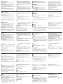
B
Package Contents
1 VK258 8-Channel Digital I/O Expansion Box
1 Rack Mount Kit
9 Terminal Blocks
1 User Instructions
Front View
Mounting
Rear View
Installation
© Copyright 2019 ATEN
®
International Co., Ltd.
ATEN and the ATEN logo are trademarks of ATEN International Co., Ltd. All rights reserved. All
other trademarks are the property of their respective owners.
This product is RoHS compliant.
Part No. PAPE-1223-R80G Printing Date: 07/2019
8-Channel Digital I/O Expansion Box
Quick Start Guide
VK258
ATEN VanCryst
™
A
Hardware Review
Front View
1
I/O LEDs: Light green to indicate that signals are being transmitted between
an I/O device and an ATEN controller. Blink green to indicate that a fi rmware
upgrade is in progress.
2
LAN LED: Lights green when the VK258 is connected to the network.
3
VK Link LED: Lights green when the VK258 has established a connection
with the connected ATEN controller.
4
DC Output Overload LED: Lights orange when the DC output exceeds the
maximum output allowable. In this case, disconnect all the devices to lower
the power output and then reboot the unit.
5
USB Port: Receives a USB drive to upgrade the fi rmware.
6
USB LED: Lights green to indicate that a fi rmware upgrade is in progress via
a USB device and turns off when the upgrade is complete. Lights orange to
indicate that the upgrade was unsuccessful.
7
Reset Button: Press once to reset the network settings. The LAN LED turns
off and lights green again to indicate that the settings are reset. To reboot
7
DC Output Port: Supplies a total power output of 12 VDC/300mA max to the
connected I/O devices.
B
Installation
Rack Mounting
1
Use the supplied screws to attach the brackets to both sides of the unit.
2
Screw the brackets to the rack, as shown in diagram B-2.
Hardware Setup
1. Use a grounding wire to ground the unit by connecting one end to the grounding
terminal, and the other end to a suitable grounded object.
Note: Do not omit this step. Proper grounding helps prevent damage to the unit
from power surges or static electricity.
2. Connect up to eight digital I/O devices using the supplied terminal blocks.
3. (Optional) If the connected I/O devices do not have their own power supply,
connect the I/O devices to the DC Output Port using the supplied terminal block.
Support and Documentation Notice
All information, documentation, fi rmware,
software utilities, and specifi cations contained in
this package are subject to change without prior
notifi cation by the manufacturer.
To reduce the environmental impact of our
products, ATEN documentation and software can
be found online at
http://www.aten.com/download/
Technical Support
www.aten.com/support
이 기기는 업무용(A급) 전자파적합기기로서 판매자 또는 사용자는 이 점을
주의하시기 바라며, 가정외의 지역에서 사용하는 것을 목적으로 합니다.
Scan for
more information
EMC Information
FEDERAL COMMUNICATIONS COMMISSION INTERFERENCE
STATEMENT:
This equipment has been tested and found to comply with the limits
for a Class A digital device, pursuant to Part 15 of the FCC Rules.
These limits are designed to provide reasonable protection against
harmful interference when the equipment is operated in a commercial
environment. This equipment generates, uses, and can radiate radio
frequency energy and, if not installed and used in accordance with
the instruction manual, may cause harmful interference to radio
communications. Operation of this equipment in a residential area
is likely to cause harmful interference in which case the user will be
required to correct the interference at his own expense.
FCC Caution: Any changes or modifi cations not expressly approved by
the party responsible for compliance could void the user's authority to
operate this equipment.
Warning: Operation of this equipment in a residential environment
could cause radio interference.
This device complies with Part 15 of the FCC Rules. Operation is subject
to the following two conditions:(1) this device mat not cause harmful
interference, and(2) this device must accept any interference received,
including interference that may cause undesired operation.
Important. Before proceeding, download the Installation and Operation
Manual by visiting the website, www.aten.com and navigating to
the product page. The manual includes important warnings, loading
specifi cations and grounding instructions.
4. Use an Ethernet cable to connect the unit’s LAN Port to a PoE switch. This
connects the unit to the network and receives power at the same time.
5. (Optional) To supply power via a power adapter, plug a power adapter into
the unit’s Power Jack and to an AC power source.
6. Use the Controller ID Switch to specify the ID of the ATEN Controller to which
the unit connects.
7. Use the Expander ID Switch to assign an ID for the unit.
Software Confi guration
1. In ATEN Confi gurator (VK6000), open a project fi le.
2. Add the unit to the project and then confi gure the installed I/O devices.
3. Upload the project to the controller. The VK LED lights green when the unit is
successfully connected to the controller.
the unit, press and hold the button for 8 seconds, until all I/O LEDs light once
in unison. In about 5 seconds, all I/O LEDs light green to indicate that the unit is
booting up. The reboot is complete when the I/O LEDs turn off.
8
Power LED: Lights green to indicate that the unit is receiving power.
Rear View
1
Controller ID Switch: Sets the ID of the ATEN controller to which the unit
connects.
2
Expander ID Switch: Sets an ID for the unit; the ID will be required when
confi guring the unit in ATEN Confi gurator (VK6000).
3
I/O Channels: Connect up to eight I/O devices.
• Digital input: programmable input range 1 – 24VDC or contact closure with +12
VDC pull-up
• Digital output: 300 mA sink from 24 VDC
4
Grounding Terminal: Receives a grounding wire.
5
Power Jack: Receives a power adapter wire.
6
Ethernet Port: Receives an Ethernet cable.
1
2
5 6
7
3
4
1
2
3 5 6
7
84
or
1
2
www.aten.com
A
Overview
La page est en cours de chargement...
-
 1
1
-
 2
2


ATEN VK258 Guide de démarrage rapide
- Catégorie
- Boîtiers de commutation série
- Taper
- Guide de démarrage rapide
dans d''autres langues
- italiano: ATEN VK258 Guida Rapida
- English: ATEN VK258 Quick start guide
- español: ATEN VK258 Guía de inicio rápido
- Deutsch: ATEN VK258 Schnellstartanleitung
- русский: ATEN VK258 Инструкция по началу работы
- português: ATEN VK258 Guia rápido
- polski: ATEN VK258 Skrócona instrukcja obsługi
- 日本語: ATEN VK258 クイックスタートガイド
- Türkçe: ATEN VK258 Hızlı başlangıç Kılavuzu
Documents connexes
-
ATEN VK2100 Guide de démarrage rapide
-
ATEN VK1100 Guide de démarrage rapide
-
ATEN VK0100 Guide de démarrage rapide
-
ATEN VK0200 Guide de démarrage rapide
-
ATEN UCE32100 Guide de démarrage rapide
-
-
-
ATEN VK108US Guide de démarrage rapide
-
-
ATEN VK224 Guide de démarrage rapide