
A
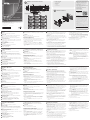
Panoramica dell'Hardware
1
Bottoni
Il layout è personalizzato usando da 6 a 12 bottoni.
2
Bottoni dei LEDs
• Le luci arancioni indicano che il bottone sta fornendo elettricità.
• Le luci bianche indicano che il bottone è attivato ed in operazione.
• Luci che alternano arancione e bianco indicano un aggiornamento
in corso.
3
Indicatori del sistema LED
• LAN: le luci verdi indicano che il VK112EU è connesso alla
Connessione Locale.
• Link: le luci verdi indicano che il VK112EU è connesso alla console di
controllo assegnata.
4
Bottone per il reset
Per resettare la rete, clicca "default settings".
5
Per alimentazione CC
Connetti l'adattatore ala morsettiera.
6
Cambiare l'ID della tastiera (blu)
Imposta l'ID del VK112EU.
7
Cambiare l'ID della console di controllo (nero)
Assegna il VK112EU ad una console di controllo semplicemente
specifi cando l'ID della console.
8
Porta LAN
• Connetti il VK112EU alla LAN.
• Fornisci corrente usando un cavo Ethernet.
Confi gurazione della tastiera
Crea un profi lo che defi nisca il layout e l'azione di ogni bottone per
il dispositivo VK112EU usando il confi guratore ATEN del Software
(VK6000).
1. Scarica ed installa il confi guratore ATEN dal sito web dell'ATEN.
2. Avvia il confi guratore ATEN.
3. Nel confi guratore ATEN, vai su Design e seleziona Keypad.
4. Segui le istruzioni che compariranno sullo schermo per creare un
profi lo e defi nire l'azione di ogni bottone.
5. Vai su Upload per caricare il profi lo sulla console di controllo
desiderata.
B
Installazione Hardware
1. Assicurati di aver creato e caricato un profi lo tastiera nel Quadro di
controllo seguendo i passaggi della Confi gurazione della Tastiera in
questa guida all'avvio rapido.
2. Aggiusta il tasto per cambiare l'ID della tastiera (blu) per assegnare
un numero ID al VK112EU.
3. Aggiusta il tasto per cambiare l'ID della console dii controllo (nero)
per specifi care il numero ID della console a cui la tastiera sarà
assegnata. Una console ATEN può funzionare con un massimo di 8
tastiere ATEN.
4. Connetti la tastiera alla LAN usando un cavo Ethernet per dare la
connessione.
Nota: PoE è supportato solo se un accessorio che fa da fonte di
corrente è installato.
5. Se non disponi di un accessorio che faccia da fonte di corrente
attraverso il cavo Ethernet, segui i seguenti passaggi per preparare il
cavo e connettere dispositivo VK112EU all'adattatore.
a. Taglia il connettore fi nale del cavo dell'adattatore.
b. Rimuovi 0,5 cm del rivestimento insulante del cavo dell'adattatore
per esporre I due cavi, il cavo da 5V+ ed il fi lo di messa a terra.
c. Inserisci i cavi esposti nella morsettiera di 2-pin fornita.
Consiglio: Per determinare la polarità del cavo, puoi usare il
voltimetro.
6. La LAN ed il Link LEDs della luce verde indicano che il VK112EU è
stato connesso con successo alla console di controllo assegnata.
Nota: La tastiera si adatta all'indirizzo IP predisposto
(192.168.0.60) in caso che la rete non supporti il DHCP. Per
confi gurare l'indirizzo IP, accedi all'interfaccia web usando
l'indirizzo predisposto e la password (password).
7. Assicura la tastiera alla parete.
8. Segui il layout della tastiera che hai creato nel profi lo ed assembla il
bottoni sulla tastiera.
9. Aggiungi la copertura alla tastiera.
Sistema di controllo VK 112 EU ATEN – Tastiera da 12 bottoni (EU, 2 Gang)
www.aten.com
A
Vista general del hardware
1
Botones
El diseño es personalizable usando 6 a 12 botones.
2
LEDs de botones
• se ilumina en naranja para indicar que el botón está alimentado.
• se ilumina en blanco para indicar que el botón está en funcionamiento.
• parpadea en naranja y blanco para indicar que la actualización del
fi rmware está en curso.
3
Indicadores LED del sistema
• LAN: se ilumina en verde para indicar que el VK112EU está
conectado a la LAN.
• Link: se ilumina en verde para indicar que el VK112EU está
conectado a la caja de control asignada.
4
Pulsador de reinicio
Presionar para restablecer la red a la confi guración predeterminada.
5
Alimentación DC
Conecte el adaptador de corriente al bloque de terminales.
6
Conmutador de identifi cación del teclado (azul)
Ajusta la identifi cación del VK112EU.
7
Interruptor de identifi cación de la caja de control
(negro)
Asigna el VK112EU a una caja de control especifi cando la
identifi cación de la caja de control.
8
Puerto LAN
• Conecta el VK112EU a la LAN.
• Suministra energía a través de Ethernet mediante un cable Ethernet.
Confi guración del teclado
Crea un perfi l que defi ne el diseño físico y las acciones de los botones
para el VK112EU utilizando el Confi gurador ATEN (VK6000).
1. Descargue e instale el Confi gurador ATEN desde la página web de
ATEN.
2. Ejecute el Confi gurador ATEN.
3. En el Confi gurador ATEN, vaya a Design y seleccione Keypad.
4. Siga las instrucciones en pantalla para crear un perfi l y defi nir las
acciones de los botones.
5. Vaya a la fi cha Upload para subir el perfi l a la caja de control
deseada.
B
Instalación del hardware
1. Asegúrese de haber creado y subido un perfi l de teclado a la caja
de control siguiendo los pasos en Confi guración del teclado en esta
guía de instalación rápida.
2. Ajuste el conmutador de identifi cación del teclado (azul) para
asignar un número de identifi cación para el VK112EU.
3. Ajuste el conmutador de identifi cación de la caja de control (negro)
para especifi car el número de identifi cación de la caja de control
con la que trabajará el teclado. Una caja de control ATEN puede
funcionar con hasta 8 teclados ATEN.
4. Conecte el teclado a la LAN usando un cable Ethernet para
proporcionar conectividad de red y alimentación.
Nota: PoE solo se admite si se instala un equipo de fuente de
alimentación.
5. Si no tiene un equipo de fuente de alimentación para suministrar
energía a través del cable Ethernet, siga los pasos a continuación
para preparar el cable de alimentación y conectar el VK112EU al
adaptador de alimentación.
a. Corte el extremo del conector del cable del adaptador de
corriente.
b. Pele 0,5 cm de la funda aislante del cable del adaptador de
alimentación para exponer los dos cables, el cable de +5V y el
cable de conexión a tierra.
c. Inserte los cables expuestos en el bloque de terminales de 2
pines suministrado.
Consejo: Para determinar la polaridad del cable, puede usar un
voltímetro.
6. Los LEDs de LAN y Link se iluminan en verde para indicar que el
VK112EU se ha conectado con éxito a la caja de control asignada.
Nota: El teclado adopta la dirección IP predeterminada
(192.168.0.60) si el conmutador de red no soporta DHCP.
Para confi gurar la dirección IP, inicie sesión en la interfaz
web utilizando la dirección IP predeterminada y la contraseña
predeterminada (password).
7. Fije el teclado a la pared.
8. Siga el diseño del teclado creado en el perfi l y coloque las tapas de
los botones en el teclado.
9. Coloque la placa frontal en el teclado.
Sistema de control VK112EU ATEN - Teclado de 12 botones (EU, 2 Gang)
www.aten.com
A
Hardware Übersicht
1
Tasten
Das Layout ist mit 6 bis 12 Tasten anpassbar.
2
Tasten-LEDs
• leuchtet orange, um anzuzeigen, dass die Taste mit Strom versorgt
wird.
• leuchtet weiß, um anzuzeigen, dass die Taste in Betrieb ist.
• blinkt orange und weiß, um anzuzeigen, dass die Firmware-
Aktualisierung läuft.
3
System LED-Anzeigen
• LAN: leuchtet grün, um anzuzeigen, dass das VK112EU mit dem
LAN verbunden ist.
• Link: leuchtet grün, um anzuzeigen, dass das VK112EU an die
zugeordnete Kontrollbox angeschlossen ist.
4
Zurücksetzen Drucktaste
Hier drücken, um das Netzwerk auf die Standardeinstellungen
zurückzusetzen.
5
Gleichstrom
Schließen Sie das Netzteil an den Anschlussblock an.
6
Keypad ID Schalter (blau)
Legt die ID des VK112EU fest.
7
Kontrollbox ID Schalter (schwarz)
Weist das VK112EU einer Kontrollbox zu, indem es die ID der
Kontrollbox angibt.
8
LAN Port
• Verbindet das VK112EU mit LAN.
• Stromversorgung über Ethernet mittels Ethernetkabel.
Keypad Konfi guration
Erstellen Sie ein Profi l, welches das physikalische Layout und
Tastenaktionen für das VK112EU mit der Software ATEN Confi gurator
(VK6000) defi niert.
1. Laden Sie den ATEN Confi gurator von der ATEN Webseite herunter
und installieren Sie ihn.
2. Führen Sie den ATEN Confi gurator aus.
3. Gehen Sie im ATEN Confi gurator zu Design und wählen Sie
Keypad.
4. Folgen Sie den Anweisungen auf dem Bildschirm, um ein Profi l zu
erstellen und Tastenaktionen zu defi nieren.
5. Wechseln Sie auf die Registerkarte Upload, um das Profi l in die
gewünschte Kontrollbox hochzuladen.
B
Hardware Installation
1. Stellen Sie sicher, dass Sie ein Keypad Profi l erstellt und in die
Kontrollbox hochgeladen haben, indem Sie die Schritte in dieser
Schnellstartanleitung unter Keypad Konfi guration befolgen.
2. Stellen Sie den Keypad ID Schalter (blau) so ein, dass eine ID-Nummer
für das VK112EU zugewiesen wird.
3. Stellen Sie den Kontrollbox ID Schalter (schwarz) ein, um die
ID-Nummer der Kontrollbox anzugeben, mit der das Keypad
arbeiten soll. Eine ATEN Kontrollbox kann mit bis zu 8 ATEN
Keypads arbeiten.
4. Schließen Sie das Keypad über ein Ethernetkabel an das LAN an,
um Netzwerkverbindung und Stromversorgung zu gewährleisten.
Hinweis: PoE wird nur unterstützt, wenn eine Stromquelle
installiert ist.
5. Wenn Sie keine Stromquelle zur Stromversorgung über das
Ethernetkabel besitzen, führen Sie die folgenden Schritte aus, um
das Netzkabel vorzubereiten und das VK112EU an das Netzteil
anzuschließen.
a. Schneiden Sie das Steckerende des Netzteilkabels ab.
b. 0,5 cm von der Isolierkappe des Netzteilkabels abisolieren,
um die beiden Adern, das +5V-Kabel und das Erdungskabel
freizulegen.
c. Stecken Sie die freiliegenden Kabel in den mitgelieferten
2-poligen Anschlussblock.
Tipp: Zur Bestimmung der Polarität des Kabels kann ein Voltmeter
verwendet werden.
6. Die LAN und Link LEDs leuchten grün, um anzuzeigen, dass das
VK112EU erfolgreich mit der zugeordneten Kontrollbox verbunden
ist.
Hinweis: Das Keypad übernimmt die Standard IP-Adresse
(192.168.0.60), wenn der Netzwerk-Switch DHCP
nicht unterstützt. Um die IP-Adresse zu konfi gurieren,
melden Sie sich mit der Standard IP-Adresse und dem
Standardkennwort (password) am Web-Interface an.
7. Schrauben Sie das Keypad an die Wand.
8. Folgen Sie dem Keypad-Layout, das Sie im Profi l erstellt haben, und
montieren Sie die Tastenkappen auf dem Keypad.
9. Befestigen Sie die Frontplatte am Keypad.
VK112EU ATEN Kontrollsystem - 12-Tasten Keypad (EU, 2 Serie)
www.aten.com
A
Survol du matériel
1
Boutons
La mise en page est personnalisable à l'aide de 6 à 12 boutons.
2
Bouton LED
• s'éclaire en orange pour indiquer que le bouton est sous tension.
• s'éclaire en blanc pour indiquer que le bouton est en marche.
• Clignote orange et blanc pour indiquer que le mise à jour du micro
logiciel est en cours.
3
Indicateurs LED
• LAN : s'allume en vert pour indiquer que le VK112EU est connecté
au réseau local.
• Link : s'allume en vert pour indiquer que le VK112EU est connecté à
la boîte de commande assignée.
4
Bouton de Réinitialisation
Appuyez pour rétablir le réseau par défaut.
5
Courant continu
Branchez l'adaptateur secteur au bloc de connexion.
6
Commutateur d'ID de Clavier (bleu)
Règle l'ID du VK112EU.
7
Commutateur de l'ID du boitier de commande (noir)
Assigne le VK112EU à un boitier de commande en spécifi ant l'ID du
boitier de commande.
8
Port LAN
• Raccorde le VK112EU au LAN.
• Alimente l'Ethernet avec un câble Ethernet.
Confi guration du clavier
Créez un profi l qui défi nit les actions de mise en page et les actions
des boutons pour le VK112EU à l'aide du logiciel de confi guration
ATEN (VK6000).
1. Téléchargez et installez le Confi gurateur ATEN depuis le site
internet d'ATEN.
2. Exécutez le Confi gurateur ATEN.
3. Dans le Confi gurateur ATEN, allez à Design et sélectionnez
Keypad.
4. Suivez les instructions à l'écran pour créer un profi l et défi nir
l'action des boutons.
5. Allez à l'onglet Upload pour charger le profi l dans le boitier de
contrôle souhaité.
B
Installation matérielle
1. Assurez-vous d'avoir créé et téléchargé un profi l de clavier vers la
boîte de contrôle en suivant les étapes de Confi guration du clavier
contenues dans ce guide de démarrage rapide.
2. Réglez le commutateur d'ID du clavier (bleu) pour affecter un
numéro d'ID pour le VK112EU.
3. Réglez le commutateur d'ID de la boîte de contrôle (noire) pour
spécifi er le numéro d'identifi cation de la boîte de contrôle avec
laquelle le clavier fonctionne. Une boite de contrôle ATEN peut
fonctionner avec au maximum 8 claviers ATEN.
4. Connectez le clavier au LAN en utilisant le câble Ethernet afi n de
fournir une connexion réseau et de l'alimentation.
Remarque : PoE est pris en charge uniquement si un équipement
d'approvisionnement en alimentation est installé.
5. Si vous n'avez pas d'équipement d'approvisionnement en
alimentation pour fournir l'alimentation via le câble Ethernet, suivez
les étapes ci-dessous pour préparer le câble d'alimentation et
connectez le VK112EU à l'adaptateur secteur.
a. Coupez l'extrémité du connecteur du câble adaptateur.
b. Bande de 0,5 cm sur le couvercle d'isolation du câble de
l'adaptateur pour exposer les deux fi ls, le fi l +5V et le fi l de terre.
c. Insérez les fi ls exposés dans le bloc de connexion 2 broches
fourni.
Conseil : Pour déterminer la polarité des fi ls, vous pouvez utiliser
un voltmètre.
6. Le LAN et les LEDs des Link s'allument en vert pour indiquer que le
VK112EU s'est lié avec succès à la boite de contrôle assignée.
Remarque : Le clavier adopte l'adresse IP par défaut
(192.168.0.60) Si le commutateur de réseau ne
supporte pas de DHCP. Pour confi gurer l'adresse IP,
connectez-vous à l'interface web à l'aide de l'adresse
IP et le mot de passe par défaut (password).
7. Sécurisez le clavier au mur.
8. Suivre la disposition du clavier que vous avez créé dans le profi l et
assemblez les capuchons de bouton sur le clavier.
9. Fixez la façade sur le clavier.
Système de Contrôle VK112EU ATEN - Clavier à 12 Touches (EU, 2 Gang)
www.aten.com
A
Hardware Overview
1
Buttons
The layout is customizable using 6 to 12 buttons.
2
Button LEDs
• lights orange to indicate that the button is supplied with power.
• lights white to indicate that the button is in operation.
• blinks orange and white to indicate that fi rmware upgrade is in
progress.
3
System LED Indicators
• LAN: lights green to indicate that the VK112EU is connected to LAN.
• Link: lights green to indicate that the VK112EU is connected to the
assigned Control Box.
4
Reset Pushbutton
Press to reset the network to default settings.
5
DC Power
Connect the power adapter into the terminal block.
6
Keypad ID Switch (blue)
Sets the ID of the VK112EU.
7
Control Box ID Switch (black)
Assigns the VK112EU to a Control Box by specifying the Control Box’s
ID.
8
LAN Port
• Connects the VK112EU to LAN.
• Supplies Power over Ethernet using an Ethernet cable.
Keypad Confi guration
Create a profi le that defi nes the physical layout and button actions for
the VK112EU using the ATEN Confi gurator (VK6000) software.
1. Download and install the ATEN Confi gurator from the ATEN
website.
2. Execute the ATEN Confi gurator.
3. In the ATEN Confi gurator, go to Design and select Keypad.
4. Follow the on-screen instructions to create a profi le and defi ne
button actions.
5. Go to the Upload tab to upload the profi le to the desired Control
Box.
B
Hardware Installation
1. Make sure you have created and uploaded a keypad profi le to the
Control Box following the steps in Keypad Confi guration in this
quick start guide.
2. Adjust the keypad ID switch (blue) to assign an ID number of the
VK112EU.
3. Adjust the Control Box ID switch (black) to specify the ID number of
the Control Box which the keypad will work with. One ATEN Control
Box can work with up to 8 ATEN keypads.
4. Connect the keypad to LAN using an Ethernet cable to provide
network connectivity and power.
Note: PoE is only supported if a power sourcing equipment is
installed.
5. If you do not have a power sourcing equipment to supply power
through the Ethernet cable, follow the steps below to prepare the
power cord and connect the VK112EU to the power adapter.
a. Cut the connector end of the power adapter cable.
b. Strip 0.5 cm off the insulation cover of the power adapter cable
to expose the two wires, the +5V wire, and the grounding wire.
c. Insert the exposed wires into the supplied 2-pin terminal block.
Tip: To determine the wire polarity, you can use a voltmeter.
6. The LAN and Link LEDs light green to indicate that the VK112EU
successfully links to the assigned Control Box.
Note: The keypad adopts the default IP address (192.168.0.60) if
the network switch does not support DHCP. To confi gure
the IP address, log in the web interface using the default IP
address and the default password (password).
7. Secure the keypad to the wall.
8. Follow the keypad layout you have created in the profi le and
assemble the button caps onto the keypad.
9. Attach the faceplate to the keypad.
VK112EU ATEN Control System – 12-Button Keypad (EU, 2 Gang)
www.aten.com
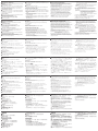
B
Package Contents
1 VK112EU Keypad
18 Buttons
1 Terminal Block
1 Faceplate
1 User Instructions
Front View
Keypad Layout Example
© Copyright 2017 ATEN
®
International Co., Ltd.
ATEN and the ATEN logo are trademarks of ATEN International Co., Ltd. All rights reserved. All
other trademarks are the property of their respective owners.
This product is RoHS compliant.
Part No. PAPE-1223-K60G Printing Date: 11/2017
ATEN Control System – 12-Button Keypad
(EU, 2 Gang)
Quick Start Guide
VK112EU
ATEN VanCryst
™
Support and Documentation Notice
All information, documentation, fi rmware,
software utilities, and specifi cations
contained in this package are subject to
change without prior notifi cation by
the manufacturer.
To reduce the environmental impact of our
products, ATEN documentation and software
can be found online at
http://www.aten.com/download/
Technical Support
www.aten.com/support
이 기기는 업무용(A급) 전자파적합기기로서 판매자 또는
사용자는 이 점을 주의하시기 바라며, 가정외의 지역에
서 사용하는 것을 목적으로 합니다.
Scan for
more information
EMC Information
FEDERAL COMMUNICATIONS COMMISSION INTERFERENCE
STATEMENT:
This equipment has been tested and found to comply with the limits
for a Class A digital device, pursuant to Part 15 of the FCC Rules.
These limits are designed to provide reasonable protection against
harmful interference when the equipment is operated in a commercial
environment. This equipment generates, uses, and can radiate radio
frequency energy and, if not installed and used in accordance with
the instruction manual, may cause harmful interference to radio
communications. Operation of this equipment in a residential area
is likely to cause harmful interference in which case the user will be
required to correct the interference at his own expense.
FCC Caution: Any changes or modifi cations not expressly approved by
the party responsible for compliance could void the user's authority to
operate this equipment.
Warning: Operation of this equipment in a residential environment
could cause radio interference.
This device complies with Part 15 of the FCC Rules. Operation is subject
to the following two conditions:(1) this device may not cause harmful
interference, and(2) this device must accept any interference received,
including interference that may cause undesired operation.
A
Hardware Overview and Connections
2
3
7
5
6
4
1 8
68.51 mm
49.5 mm
28 mm
Hardware Installation
La page charge ...
-
 1
1
-
 2
2


dans d''autres langues
- italiano: ATEN VK112EU Guida Rapida
- English: ATEN VK112EU Quick start guide
- español: ATEN VK112EU Guía de inicio rápido
- Deutsch: ATEN VK112EU Schnellstartanleitung
- русский: ATEN VK112EU Инструкция по началу работы
- português: ATEN VK112EU Guia rápido
- 日本語: ATEN VK112EU クイックスタートガイド
Documents connexes
-
ATEN VK108US Guide de démarrage rapide
-
ATEN VK0100 Guide de démarrage rapide
-
ATEN VK0200 Mode d'emploi
-
ATEN VK1100 Guide de démarrage rapide
-
-
-
-
-
ATEN VK2100 Guide de démarrage rapide
-