
P/NO. 3828W5U0270
Printed in Korea
LMV-1631SW
LMV-1631SB
MICROWAVE OVEN
INSTALLATION INSTRUCTIONS
PLEASE READ AND SAVE
THESE INSTALLATION INSTRUCTIONS.
website: http://www.lg.ca

BEFORE YOU START
●
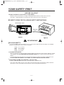
Proper installation is the installer's responsibility!
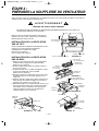
– Read the entire manual before you begin. The Model number label is located on the oven front.
See Figure 1. Mounting plate is located on back side of microwave oven. See Figure 2.
BE SURE TO READ THE FOLLOWING SAFETY INSTRUCTIONS:
FOR YOUR SAFETY:
●
You will need TWO people to install this oven. It is heavy and could cause personal injury if not handled
properly. The dimensions of the oven are as follows:
Height : 16
7/16 inches
Width : 29 15/16 inches
Depth : 15 3/8 inches
Weight : 58 pounds
●
Avoid Electrical Shock!
– Before you drill into the wall, note where electrical outlets are and where electrical wires might be behind
concealed the wall, YOU COULD GET AN ELECTRIC SHOCK it you contact electrical wires with your
drill bit.
– Locate and disconnect the power of any electrical circuits that could be affected by installing this oven.
IF YOU DO NOT DISCONNECT THE POWER, YOU COULD GET AN ELECTRIC SHOCK.
●
ELECTRICAL RATING OF THIS OVEN : 120V AC. 60Hz.
13 Amps / 1500 Watts (Microwave oven + Cooktop Lamp + Ventilation Fan)
– You need a 120V, 60Hz, AC only, 15A or 20A, fused electrical supply (located in the cabinet above the
microwave as close as possible to the microwave circuit) serving only the microwave.
YOUR SAFETY FIRST
— 2 —
Figure 1
Model Number Label
Mounting
plate
(Remove from
oven to install.)
Back of oven
Figure 2
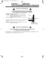
W A R N I N G

●
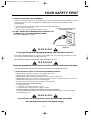
THIS APPLIANCE MUST BE GROUNDED!
– If there is an electrical short circuit, grounding reduces the risk of electrical shock by providing an escape
wire for the electric current. This appliance is equipped with a cord having a grounding wire with a
grounding plug.
●
Place the plug into a properly installed and grounded outlet. See Figure 3.
●
Do not use an extension cord.
●
Keep the power cord dry and do not pinch or crush it.
●
DO NOT, UNDER ANY CIRCUMSTANCES, REMOVE THE
POWER SUPPLY CORD GROUNDING PRONG!
This appliance MUST be grounded!
If you use the grounding plug improperly, you risk electric shock!
– Check with a qualified electrician if you are not sure whether the oven is properly grounded or if you do
not completely understand the grounding instructions.
DO NOT USE A FUSE IN THE NEUTRAL OR GROUNDING CIRCUIT.
Improper grounding could result in electric shock or other personal injury.
SAVE THESE INSTRUCTIONS FOR THE LOCAL ELECTRICAL INSPECTOR'S USE.
●
DO NOT EXPOSE YOURSELF TO EXCESSIVE MICROWAVE ENERGY!
– DO NOT try to operate the microwave oven with the door open.
– DO NOT tamper with or defeat the safety interlocks.
– DO NOT place objects between the microwave oven front face and the door.
–
DO NOT allow soil or cleaner residue to build up on the flat surfaces around the microwave oven door.
– DO NOT operate the microwave oven if it is damaged.
– The microwave oven door must close properly to operate safely.
– DO NOT USE THE MICROWAVE OVEN:
●
If the door is bent.
●
If the hinges or latches are broken or loose.
●
If the door seals, sealing surfaces or glass is broken.
– DO NOT ATTEMPT TO ADJUST OR REPAIR THE OVEN YOURSELF!
It should be adjusted and repaired by a qualified technician who can check for microwave leakage
after repairing the oven.
If you do not use the microwave oven as instructed, you could
be exposed to excessive microwave energy.
YOUR SAFETY FIRST
— 3 —
PROPERLY POLARIZED AND
GROUNDED OUTLET
Three-Pronged (Grounding) plug
Figure 3
W A R N I N G
W A R N I N G
W A R N I N G

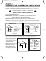
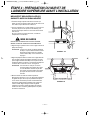
● MAKE SURE YOU HAVE ENOUGH SPACE AND SUPPORT.
– Mount the oven against a flat, vertical wall, so that it is supported by the wall. The wall should be
constructed of minimum 2" x 4" wood studding and 3/8" thick drywall or plaster/lath.
– ATTACH AT LEAST ONE of the two lag screws supporting the oven to a vertical, 2" x 4" wall stud.
– DO NOT mount the microwave oven to an island or peninsula cabinet.
– BE SURE the upper cabinet and rear wall structures are able to support 150 lbs., plus the weight of any
items you place inside the oven or upper cabinet.
– Locate the oven away from strong draft areas, such as windows, doors, and strong heating vents.
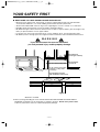
– BE SURE you have enough space. See Figure 4 below for minimum vertical and horizontal clearance.
If you do not mount the oven as instructed,
you risk personal injury and/or property damage.
C A U T I O N
● Before you begin installing the oven, PLACE APIECE OF THE CARTON OR OTHER HEAVY
MATERIAL (a blanket) over the countertop or cooktop to protect it. Do not use a plastic cover.
Failure to protect these surfaces could result inproperty damage.
YOUR SAFETY FIRST
— 4 —
30" min. cabinet opening width
30" min. clearance from bottom
of cabinet to cooking surface
or countertop
(Use templates included
with installation instructions)
Grounded Plug
(inside upper cabinet)
Power Supply
Cord Hole
Figure 4
W A R N I N G

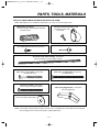
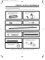
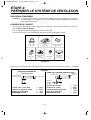
THE FOLLOWING PARTS ARE SUPPLIED WITH THE OVEN:
NOTE: Depending on your ventilation requirements, you may not use all of these parts.
NOTE: You need to install at least one lag screw into a 2" x 4" stud and four anchor bolts into the wall and
the mounting area must meet the 150 lbs. weight requirement.
PARTS, TOOLS, MATERIALS
— 5 —
Damper/duct connector
(for roof-venting or wall-venting installation)
Not Actual Size
One power cord clamp and
One dark-colored mounting screw
(to hold the power cord)
Actual Size
Two tapping screws - Actual Size
(for attaching the damper duct connector)
Four 1/4" x 2" lag screws - Actual Size
(for wall stud holes)
Two 1/4" x 2" bolts - Actual Size
(for securing to the upper cabinet)
Four spring toggle heads - Actual Size
(for the toggle bolts)
Two washers - Actual Size
(for the two upper cabinet bolts)
Four 1/4" x 3" toggle bolts - Actual Size
(for drywall holes)
One power cord clamp bushing - Actual Size
(for the cord hole in a metal upper cabinet)
One lock pin and one washer-Not Actual size

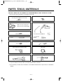
YOU WILL NEED THE FOLLOWING TOOLS AND MATERIALS FOR THE INSTALLATION:
Carton or other heavy material for covering the counter top.
● If you have brick or masonry walls, you need special hardware and tools.
● The ductwork you need for the installation is not included. All wall and roof caps must have a back-draft
damper.
PARTS, TOOLS, MATERIALS
— 6 —
Clear tape
(for taping the templates to the wall)
Stud finder or thin nail.
Saber saw (for cutting vent
hloes for roof or wall venting)
Key hole saw (for the power cord hole)
Electric drill
3/8" and 3/4" wood drill bits
1/2" and 3/16"
drill bits
Phillips screwdriver (for the screws)
Pencil
Flat blade screwdriver (for the bolts)
Measuring tape (metal preferred)
Small side cutters or tin snips
Caulking gun
Plumb line
Duct Tape

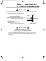
AVOID ELECTRICAL SHOCK! THIS APPLIANCE MUST BE GROUNDED!
1. Locate the grounded electric outlet for this oven in the
cabinet above the oven, as shown in Figure 4 Detail.
NOTE: The outlet should be on a circuit dedicated to the
microwave oven 120V, 60Hz., AC only, with a
20ampere fused electrical supply.
IMPORTANT: If you do not have the proper wall outlet, you
MUST have one installed by a qualified
electrician.
2. You will cut the power-supply-cord hole (shown in
Figure 4 Detail) later when you prepare the wall and
upper cabinet in Step 4.
NOTE: Do not use an extension cord.
Keep the power cord dry and do not pinch or
crush it.
Improper grounding could result in
electric shock or other personal injury.
●
DO NOT, UNDER ANY CIRCUMSTANCES, REMOVE THE POWER
SUPPLY CORD GROUNDING PRONG! This appliance MUST be
grounded!
STEP 1: PREPARE THE
ELECTRICAL CONNECTIONS
— 7 —
Grounded Outlet
Upper
Cabinet
Power-Supply-Cord Hole
Figure 4 Detail
W A R N I N G
W A R N I N G

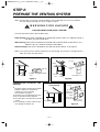
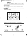
NOTE: The ductwork you need for outside ventilation is not included with your oven. The standard
ductwork fittings and length are shown in Figure 9, page 9.
THIS OVEN MUST BE PROPERLY VENTED!
You may vent your oven in one of three ways:
Roof-venting If your oven is located on an outside wall near the roof, as in Figures 6 (31/4" x
10" duct) and 8 (6" round duct.)
Wall-venting If your oven is located on an outside wall on the first floor of your house, as in
Figures 5 (3 1/4" x 10" duct) and 8 (6" round duct.)
Room-venting If your oven is located on an inside wall of your house, as in Figure 7.
NOTE: If you choose the rear exhaust method (roof-or wall-venting), be sure there is enough clearance
within the wall for the exhaust duct.
REMEMBER AS YOU INSTALL THE
VENTING:
●
Keep the length of the ductwork and the
number of elbows to a minimum to
ventilate your oven efficiently.
See examples on page 9.
●
Keep the size of the ductwork the same.
●
Do not install two elbows together.
●
Use duct tape to seal all joints in the duct
system.
●
Use caulking to seal the exterior wall or
roof opening around the cap.
STEP 2:
PREPARE THE VENTING SYSTEM
— 8 —
Wall Venting
Wall venting
through-the-wall
wall cap
3 1/4"x10"
duct
Figure 5
cabinet
oven
Roof Venting
through-the-roof
3 1/4"x10"
duct
Figure 6
roof cap
Roof venting
cabinet
oven
6" min.
diameter
round duct
3 1/4" to round
duct transition
3 1/4" to round
ductwork transition
Figure 8
roof cap
wall cap
elbow
W A R N I N G -F I R E H A Z A R D
Room Venting
Figure 7
cabinet
oven

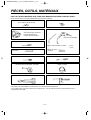
STANDARD FITTINGS
NOTE: If the existing duct is round, you must use a rectangular-to-round adapter, with a rectangular 3"
extension duct installed between the damper assembly and the adapter to prevent the exhaust
damper sticking.
DUCT LENGTH
The total length of the duct system, including straight duct, elbows, transitions, wall or roof caps must not
exceed the equivalent of 140 feet.
For best performance, do not use more than three 90 degree elbows.
Below are the standard fittings and their equivalent length in feet.
To calculate the equivalent length of each duct piece used, see the examples below.
STEP 2:
PREPARE THE VENTING SYSYTEM
— 9 —
Figure 9
1
4567
23
3 1/4"x10"
to 6"=5ft.
90˚ elbow
=10ft.
45˚ elbow
=5ft.
3 1/4"x10"
wall cap
=40ft.
3 1/4"x10"
flat elbow
=10ft.
3 1/4"x10" roof
cap=24ft.
3 1/4"x10" 90˚
elbow=25ft.
Examples
For 3 1/4"x10" SYSTEMS
1-3 1/4" x 10" 90˚ elbow
1-Wall Cap
8 feet straight duct
TOTAL LENGTH
1-transition
2-90˚ elbows
1-Wall Cap
8 feet straight
TOTAL LENGTH
For 6" ROUND SYSTEMS
6ft.
2ft.
2ft.
3 1/4"x10"
90˚ elbow
wall cap
6ft.
90˚ elbows
transition
wall cap
= 25 ft.
= 40 ft.
= 8 ft.
= 73 ft.
= 5 ft.
= 20 ft.
= 40 ft.
= 8 ft.
= 73 ft.

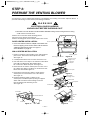
Your microwave oven is shipped with the blower assembled for roof venting. You need to adjust the blower if
you want wall-venting or room-vented (recirculating) installation.
ELECTRICAL SHOCK HAZARD!
UNPLUG UNIT BEFORE WORKING ON IT.
●
DO NOT PULL OR STRETCH THE BLOWER WIRING! Pulling and stretching the blower wiring
could result in electrical shock.
STEP 3:
PREPARE THE VENTING BLOWER
— 10 —
Figure 10
Figure 11
Figure 12
Figure 14
Figure 13
Mounting plate
Mounting plate screws
Control panel side
blower plate
mounting screw
blower unit
Parts "B"
back plate
blower plate
Knockouts Parts "B"
Parts "B"
back Plate
blower
unit
exhaust
ports
back plate
Damper
Exhaust
adaptor
Tapping screw
(Bright color)
W A R N I N G
Remove two screws that attach mounting plate to
microwave oven cabinet. See Figure 10.
Remove mounting plate and set aside. Replace the screws.
ROOF-VENTED INSTALLATION:
1. Insert one side of exhaust adaptor and attach with
the one tapping screw on the other side of exhaust
adaptor to the blower plate. See Figure 11.
Go to STEP 4 on page 12.
WALL-VENTED INSTALLATION:
1. Remove one blower unit mounting screw and two blower
plate screws. Remove the blower plate from cabinet.
See Figure 12.
2. Carefully lift the blower unit out of the microwave oven.
3. Use side cutters or tin snips to cut and remove knockouts
parts “B” from Back plate. Discard knockouts.
Be careful not to distort the plate. See Figure 13.
4. Rotate the unit so that the exhaust ports face the rear of
the cabinet. See Figure 14. When you insert blower unit,
blower wire must be like figure 14.
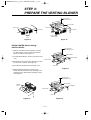
5. Place blower unit back into cabinet. Check that the
exhaust ports face towards the rear of the cabinet.
See Figure 15.
6. Reattach the blower plate to cabinet so the
exhaust ports and blower plate opening are aligned.
Attach with one blower unit mounting screw and
then two blower plate mounting screws.
See Figure 16.

ROOM-VENTED (Recirculating)
INSTALLATION:
1. Remove one blower unit mounting screw and
two blower plate screws. Remove the blower
plate from cabinet. See Figure 17.
2. Carefully lift the blower unit out of the microwave
oven.
3. Rotate blower unit so that the exhaust ports face
the front of the cabinet. See Figure 18.
4. Place blower unit back into microwave oven.
5. Reattach blower plate to microwave oven.
Attach with the one blower unit mounting screw
and then the two blower plate mounting screws.
See Figure 19.
STEP 3:
PREPARE THE VENTING BLOWER
— 11 —
Figure 16Figure 15
exhaust
ports
blower unit
back plate
blower unit
exhaust ports
blower plate
mounting screw
blower unit
blower plate
back plate
Figure 17
blower plate
mounting screw
blower unit
Parts "B"
back plate
blower plate
Figure 18 Figure 19
exhaust
ports
blower plate
mounting screw
blower unit
Parts "B"
back plate
blower plate

MEASURE AND TACK / TAPE UP THE
TEMPLATES
1. Using a plumb line and (metal) measuring tape, find
and mark the vertical center line on the back wall, as
in Figure 22.
2. Find and mark one or two points where the studs are
on the wall (Studs are normally 16 inches apart.)
and then measure and mark the stud locations. If
you cannot find any wall stud, consult a local
building contractor.
DO NOT ATTEMPT TO INSTALL THE MICROWAVE
OVEN IF YOU CANNOT FIND A WALL STUD.
3. Line up the plumb line on the wall with the center
line on the mounting plate.
NOTE: Be sure the minimum width is 30 inches and
the distance from the top of the mounting
plate to the range or counter top is at least 30
inches. See Figure 4 on page 4.
4. Center mounting plate in operating by lining up the
plumb line on wall with centerline on mounting plate.
Make sure the minimum width is 30 inches and that
the top of the mounting plate is located a minimum of
30 inches above the cooking surface.
See Figure 23.
NOTE: f the cabinets are not plumb, adjust the
mounting plate to the cabinets. If the front
edge of the cabinet is lower than the back
edge, adjust the mounting plate to be level
with the cabinet front.
5. Measure the bottom of the upper cabinet frame. Trim
the edges "A" "B" and "C" on the upper cabinet
template so that the template will fit on the bottom of
the upper cabinet. If upper cabinet has a recessed
frame, trim template so that it fits inside the
recessed area. Align the centerline of the upper
cabinet template with the centerline of the mounting
plate; then securely tape or tack the upper cabinet
template in place. See Figure 23
STEP 4: PREPARE THE WALL AND
UPPER CABINET FOR INSTALLATION
— 12 —
Figure 22
Figure 23
CAUTION

STEP 4: PREPARE THE WALL AND
UPPER CABINET FOR INSTALLATION
— 13 —
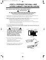
DRILL THE HOLES IN THE WALL AND UPPER CABINET.
BE VERY CAREFUL WHEN DRILLING HOLES INTO THE WALL.
Electrical wires could be concealed behind the wall covering
and if the drill hits them you could get an electric shock.
1. Find the points on the mounting plate labeled "A", "B", "C", and "D". Drill a 3/16" diameter hole at any
points that are over a wall stud. Drill a 3/4" diameter hole at any points over drywall.
2. Drill a 3/8" hole at points "J", "K", and "N" on the upper cabinet template.
NOTE: If the bottom of the upper cabinet is recessed 3/4" or more, you will need 2"x2" filler blocks (not
included) to provide additional support for the bolts. See Figure 24.
• Mark the center of each filler block and drill a 3/8" diameter hole at the marks.
• Align filler blocks over the two openings in the top of the microwave oven cabinet and attach to
cabinet with masking tape. See Figure 25.
3. Cut or drill a 2" diameter hole at the area marked "M".
Power supply cord hole on the upper cabinet template. If the upper cabinet is metal, you will need to cover
the edge of the hole with the power supply cord bushing (supplied) to prevent damage to the cord from the
rough metal edge.
YOU MUST COVER THE EDGE OF
THE POWER SUPPLY CORD HOLE
IN A METAL CABINET WITH THE
POWER SUPPLY CORD BUSHING.
FAILURE TO DO SO COULD
RESULT IN DAMAGE TO THE
CORD AND ELECTRIC SHOCK.
4. Cut out the venting areas (with the saber saw):
•
Roof-Vented: cut out the shaded area marked "L"
on the upper cabinet template.
•
Wall-Vented: go to STEP 5, INSTALL THE
MOUNTING PLATE, located on page 15.
5. Complete whichever venting system you have chosen.
Use caulking compound to seal the exterior wall or
roof opening around the wall cap or roof cap.
Figure 24
Figure 25
cabinet front
filler block cabinet
bottom shelf
filler
block
W A R N I N G
W A R N I N G

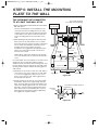
THE OVEN MUST BE CONNECTED
TO AT LEAST ONE WALL STUD.
1. Draw a vertical line on the wall at the center of the
30″ wide space.
Use the mounting plate as the template for the
rear wall. Place the mounting plate on the wall,
making sure that the tabs are against the bottom
of the cabinet. Line up the notch and center line
on the mounting plate to the center line on the
wall.
2. While holding the mounting plate with one hand,
draw circles on the wall at holes A, B, C and D.
Four holes must be used for mounting. If the holes
are not used, the installation will not be secure.
Installer must use these holes for proper
installation. Use toggle bolts through these holes
unless one of them lines up with a stud. Use a
wood screw for studs.
NOTE: Draw a fifth circle inside area E, through
one of the bottom holes to match the location of a
stud.
For wall-vented: The oven requires a rear wall cutout
opening for the rear wall duct and the exhaust
adaptor must be attached to the mounting plate. See
the next page on how to prepare the rear wall cutout
opening and the exhaust adaptor/mounting plate for
wall-vented.
3. Drill holes on the circles. If there is a stud, drill a 3
/16″ hole for lag screws. If there is no stud, drill a
3/4″ hole for toggle bolts. Make sure to use at
least 1 lag screw in a stud, and 4 toggle bolts in
the drywall or the plaster.
4. Attach the plate to the wall. To use spring toggle
heads bolts: Remove the toggle wings from the
bolts. Insert the bolts into the mounting plate and
replace the spring toggle heads to 3 / 4″ past the
bolt ends. Insert the spring toggle heads into the
holes in the wall to mount the bracket. You may
pull forward on the bracket to help in tightening
the toggle bolts. Tighten all bolts.
STEP 5:
INSTALL THE MOUNTING
PLATE TO THE WALL
— 14 —
Center Line
A
C
B
3/16" Hole on Studs
3/4" Hole on Drywall Only
Draw
Center Line
Draw Lines
on Studs
Wall
Mounting
Plate
Space More Than Wall Thickness
Bolt
End
Toggle Bolt
Toggle Wings
For Wall-
Vented Only
Minimum 66
"
From the Floor
Support Tab Support Tab
E
Mounting
Plate
Figure 26
Figure 27
D

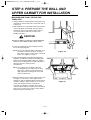
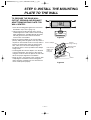
TO PREPARE THE REAR WALL
CUTOUT OPENING AND EXHAUST
ADAPTOR/MOUNTING PLATE FOR
WALL-VENTED:
1. Place the mounting plate against the rear wall as
described in step 5 item 1 (page 14).
2. Using a pencil, put dots through slots F and G,
and through holes H and I. Remove the mounting
plate and draw lines extending through the points.
This will give the location and size of the box
cutout for the rear wall duct.
• Attach the exhaust adaptor to the rear mounting
plate by sliding it into the guides at the top center of
the plate on the wall side. Push in securely until it is
past the top locking tabs and in the lower locking
tabs. Take care to assure the damper hinge is
installed so that it is at the top and that the damper
swings freely.
• Carefully guide the exhaust adaptor, now attached
to the mounting plate, into the house duct, before
using the screws to attach the plate to the wall. This
will assure proper alignment for installation.
• Return to step 5, item 3 (page 14) to continue. After
completing the installation of the mounting plate,
again check the rear damper for free movement to
assure it will operate properly.
STEP 5:
INSTALL THE MOUNTING
PLATE TO THE WALL
— 15 —
F
I
H
G
Slide exhaust
adaptor into
guides on
rear panel.
Exhaust Adaptor
Damper
(hinge side up)
Locking
Tabs
Guides
Mounting Plate
(wall side)
Figure 28
Figure 29

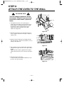
You will need two people to lift this
microwave. Failure to use more than
one person could result in personal
injury.
1. Carefully lift microwave oven and hang it on
support tabs (See Figure 26) at the bottom of the
mounting plate. Reaching through upper cabinet,
thread power supply cord through the power
supply cord hole in the bottom of the upper
cabinet. See Figure 30.
2. Rotate the microwave oven upward so the top of
oven is against the bottom of the upper cabinet or
cabinet frame.
3. Drop the lock pin and washer assembly into hole
"N" (left side hole) and push the pin down as far as
it will go. See Figure 31.
4. Place washers over two 1/4"x3" bolts. Then insert
a bolt down through each hole in the upper cabinet
bottom.
Tighten the bolts until the gap between the upper
cabinet and microwave oven is closed. See Figure
32.
5. Remove lock pin and washer.
If wall-vented or room-vented installation is used,
go to No. 8 on the next page.
STEP 6:
ATTACH THE OVEN TO THE WALL
— 16 —
Figure 30
washer
Figure 31
lock pin
power cord
power cord
hole
Figure 32
W A R N I N G

— 17 —
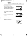
6. Roof vented installation:See Figure 33
Install ductwork through the vent opening in the
upper cabinet. Complete the venting system
through the roof according to the method needed.
See “PREPARE THE VENTING SYSTEM,” STEP
2 on the page 8. Use caulking to seal exterior roof
opening around the exhaust cap. See Figure 6 on
page 8.
7. Use power supply cord clamp to bundle the power
supply cord. Install the power supply cord clamp,
using a screw as shown in Figure 34, to inside of
the cabinet.
8. To install the grease filter: Slide it into the slide
slot, then push up and toward oven center to lock.
See Figure 35.
9. Plug in the power supply cord.
10. Read your Owner’s Manual, then check the
operation of your microwave oven.
STEP 6:
ATTACH THE OVEN TO THE WALL
Figure 33
Figure 35
Figure 34
damper
duct
power
supply
cord
clamp

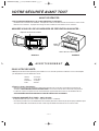
AVANT DE DÉBUTER
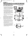
• Une installation adéquate est la responsabilité de l’installateur!
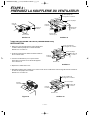
– Veuillez lire tout le manuel avant de débuter. L’étiquette du numéro de modèle est située à l’avant du four à micro-ondes.
Référez-vous au schéma 1. La plaque de montage est située à l’arrière du four. Référez-vous au schéma 2.
ASSUREZ-VOUS DE LIRE LES MESURES DE PRÉVENTION SUIVANTES :
POUR VOTRE SÉCURITÉ:
• DEUX personnes devront être présentes pour installer ce four. Il est lourd et pourrait vous blesser si vous ne le manipulez
pas adéquatement. Voici les dimensions du four :
Hauteur : 16-7/16 po.
Largeur : 29-15/16 po.
Profondeur : 15-3/8 po.
Poids : 58 livres
• Évitez les chocs électriques!
– Avant de percer dans le mur, remarquez l’emplacement des prises de courant ainsi que l’endroit où passent les fils
électriques. VOUS POURRIEZ VOUS ÉLECTROCUTER si vous touchez à des fils avec la mèche de votre perceuse.
– Localisez et coupez le courant de tous les circuits électriques qui pourraient être touchés lors de l’installation du four.
VOUS POURRIEZ VOUS ÉLECTROCUTER SI VOUS NE COUPEZ PAS LE COURANT.
• TENSION ASSIGNÉE À CE FOUR : 120V CA, 60Hz.
13 ampères/1500 watts (four à micro-ondes + ampoules de la hotte + ventilateur)
– Vous devez posséder une source d’alimentation avec fusibles (située dans l’armoire la plus proche que possible de la prise
du four) de 120V, 60Hz, CA seulement, de 15A ou 20A et qui est dédiée exclusivement au four à micro-ondes.
VOTRE SÉCURITÉ AVANT TOUT
— 2 —
Étiquette du numéro de modèle
Plaque de
montage
Arrière du four à micro-ondes
Schéma 2Schéma 1
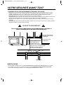
AVERTISSEMENT

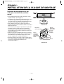
• VOUS DEVEZ EFFECTUER LA MISE À LA TERRE DE CET APPAREIL!
– S’il se produit un court-circuit, la mise à la terre réduit les risques de choc électrique en procurant une voie de sortie à
l’alimentation électrique. Cet appareil possède un cordon d’alimentation muni d’un fil et d’une fiche avec mise à la terre.
• Branchez la fiche dans une prise bien installée et mise à la terre. Référez-vous au schéma 3.
• Ne vous servez pas de cordon d’extension.
• Gardez le cordon au sec et sans le pincer ni l’écraser.
• NE COUPEZ JAMAIS LA BROCHE DE MISE À LA TERRE
DE VOTRE CORDON D’ALIMENTATION!
Cet appareil DOIT être mis à la terre!
Vous risquez de vous électrocuter si vous n’utilisez pas adéquatement
la prise avec mise à la terre!
– Consultez un électricien qualifié si vous doutez que votre four soit bien mis à la terre ou si vous ne comprenez pas
complètement les instructions de mise à la terre.
N’UTILISEZ PAS DE FUSIBLE DANS LE CIRCUIT NEUTRE OU DE MISE À LA TERRE.
Une mauvaise mise à la terre pourrait occasionner un choc électrique ou
d’autres blessures.
CONSERVEZ CES INSTRUCTIONS EN CAS D’UNE VISITE PAR L’INSPECTEUR
EN BÂTIMENTS DE VOTRE QUARTIER.
• NE VOUS EXPOSEZ PAS À UN SURPLUS D’ÉNERGIE DU FOUR À MICRO-ONDES!
– NE TENTEZ PAS de faire fonctionner le four si la porte est ouverte.
– N’ESSAYEZ PAS d’altérer ni d’annuler les mécanismes d’enclenchement de sécurité.
– NE PLACEZ PAS d’objets entre la porte et la devanture du four.
– NE LAISSEZ PAS s’accumuler les résidus de saleté ou de détergents sur les surfaces plates autour de la porte du four.
– NE FAITES PAS FONCTIONNER le four s’il est endommagé.
– La porte du four doit pouvoir se refermer parfaitement afin que l’appareil fonctionne en toute sécurité.
– N’UTILISEZ PAS LE FOUR À MICRO-ONDES :
• Si la porte est tordue.
• Si les charnières ou loquets sont brisés ou lâches.
• Si les joints d’étanchéité de la porte ou de la vitre sont brisés.
– N’ESSAYEZ PAS D’AJUSTER NI DE RÉPARER LE FOUR PAR VOUS-MÊME!
Il ne doit être ajusté et réparé que par un technicien qui peut vérifier s’il n’y a pas de fuite de micro-ondes après avoir réparé
le four.
Vous pourriez vous exposer à un surplus de micro-ondes si vous n’utilisez
pas le four à micro-ondes tel qu’indiqué.
VOTRE SÉCURITÉ AVANT TOUT
— 3 —
AVERTISSEMENT
AVERTISSEMENT
AVERTISSEMENT
PRISE DE COURANT POLARISÉE ET
ADÉQUATEMENT MISE À LA TERRE
Fiche à trois broches (avec prise de terre)
Schéma 3

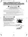
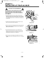
• ASSUREZ-VOUS D’AVOIR SUFFISAMMENT D’ESPACE ET DE SOUTIEN.
– Montez le four sur un mur vertical et plat afin qu’il puisse être soutenu par le mur. Le mur devrait être monté sur des
madriers d’au moins 2 po. x 4 po. et fait de plâtre, lattes ou de feuilles de gypse d’une épaisseur minimale de 3/8 po.
– VISSEZ AU MOINS UNE des deux vis à tête ronde qui supportent le four à un madrier vertical de 2 po. x 4 po.
– N’INSTALLEZ PAS le four au-dessus d’un îlot central ni sous une armoire suspendue.
– ASSUREZ-VOUS que les structures de l’armoire et du mur arrière puissent soutenir un poids de 150 lbs en plus du poids
des items que vous placez dans le four et ceux qui se trouvent déjà dans les armoires supérieures.
– Éloignez le four des endroits où les courants d’air sont trop forts tels que les fenêtres, portes et bouches de chauffage
puissantes.
– ASSUREZ-VOUS de posséder suffisamment d’espace. Référez-vous au schéma 4 ci-dessous pour calculer l’espace de
dégagement minimal sur le plan vertical et horizontal.
Vous risqueriez de vous blesser et/ou d’endommager vos biens si
vous n’installez pas le four selon les instructions.
MISE EN GARDE
• Avant de débuter l’installation du four, PLACEZ UN MORCEAU DE CARTON OU DE TISSUS ÉPAIS (une couverture)
sur le comptoir ou sur votre four conventionnel afin de le protéger. N’utilisez pas de recouvrement de plastique.
Vous pourriez endommager vos biens si vous ne protégez pas adéquatement ces surfaces.
VOTRE SÉCURITÉ AVANT TOUT
— 4 —
AVERTISSEMENT
Largeur minimale de 30 po.
pour le boîtier du four
Dégagement minimal de 30 po.
à partir du dessous du boîtier jusqu’à
la plaque de cuisson ou du comptoir du cuisine.
(Utilisez les gabarits inclus avec
les instructions d’installation.)
Prise avec mise à la terre
(à l’intérieur des armoires
supérieures)
Trou pour le cordon
d’alimentation
Schéma 4
La page charge ...
La page charge ...
La page charge ...
La page charge ...
La page charge ...
La page charge ...
La page charge ...
La page charge ...
La page charge ...
La page charge ...
La page charge ...
La page charge ...
La page charge ...
La page charge ...
-
 1
1
-
 2
2
-
 3
3
-
 4
4
-
 5
5
-
 6
6
-
 7
7
-
 8
8
-
 9
9
-
 10
10
-
 11
11
-
 12
12
-
 13
13
-
 14
14
-
 15
15
-
 16
16
-
 17
17
-
 18
18
-
 19
19
-
 20
20
-
 21
21
-
 22
22
-
 23
23
-
 24
24
-
 25
25
-
 26
26
-
 27
27
-
 28
28
-
 29
29
-
 30
30
-
 31
31
-
 32
32
-
 33
33
-
 34
34


dans d''autres langues
- English: LG MV-1643ASY Operating instructions
Documents connexes
Autres documents
-
Bosch HMV9303/01 Guide d'installation
-
Bosch HMV9305 - 1.8 cu. ft. Microwave Guide d'installation
-
Maytag MMV5207 Installation Instructions Manual
-
-
-
GE JEB1860SM2SS Guide d'installation
-
Insignia NS-OTR16WH9 Guide d'installation
-
-
CANARMNA IPL417A01 Manuel utilisateur
-