Skil CR540601 Le manuel du propriétaire
- Catégorie
- Outils électroportatifs
- Taper
- Le manuel du propriétaire

WARNING: To reduce the risk of injury, the user must read and understand the
Owner’s Manual before using this product. Save these instructions for future reference.
AVERTISSEMENT : Afin de réduire les risques de blessure, l’utilisateur doit lire et
comprendre le guide d’utilisation avant d’utiliser cet article. Conservez le présent guide
afin de pouvoir le consulter ultérieurement.
ADVERTENCIA : Para reducir el riesgo de lesiones, el usuario debe leer y comprender
el Manual del operador antes de utilizar este producto. Guarde estas instrucciones para
consultarlas en caso sea necesario.
Owner’s Manual
Guide d’utilisation
Manual del propietario
For Customer Service
Pour le service à la clientèle
Servicio al cliente
Model/ Modelo/ Modèle: CR540601
1-877-SKIL-999
OR
www.skil.com
20V 6-1/2'' Circular Saw
Scie circulaire de 20 V, 6-1/2 po
Sierra circular de 6-1/2 pulgadas de 20 V

2
TABLE OF CONTENTS
General Power Tool Safety Warnings .............................3-5
Additional Safety Instructions for Circular Saws ....................5-6
Symbols ....................................................7-10
Get to Know Your Circular Saw ...................................11
Specications .................................................12
Operating Instructions .......................................13-21
Maintenance ..................................................22
Troubleshooting ................................................23
Limited Warranty of SKIL Cordless Tool ............................24
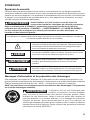
WARNING
•
Some dust created by power sanding, sawing, grinding, drilling and other construction
activities contains chemicals known to the State of California to cause cancer, birth defects
or other reproductive harm. Some examples of these chemicals are:
–
Lead from lead-based paints.
–
Crystalline silica from bricks, cement, and other masonry products.
–
Arsenic and chromium from chemically-treated lumber.
•
Your risk from these exposures varies, depending upon how often you do this type of work.
To reduce your exposure to these chemicals:
–
Work in a well-ventilated area.
–
Work with approved safety equipment, such as dust masks that are specially designed to
lter out microscopic particles.
–
Avoid prolonged contact with dust from power sanding, sawing, grinding, drilling, and
other construction activities. Wear protective clothing and wash exposed areas with soap
and water. Allowing dust to get into your mouth or eyes or to lie on the skin may promote
absorption of harmful chemicals.

3
GENERAL POWER TOOL SAFETY WARNINGS
WARNING
Read all safety warnings, instructions, illustrations and specications
provided with this power tool. Failure to follow all instructions listed
below may result in electric shock, re and/or serious injury.
SAVE ALL WARNINGS AND INSTRUCTIONS FOR FUTURE
REFERENCE.
The term “power tool” in the warnings refers to your mains-operated (corded) power tool or
battery-operated (cordless) power tool.
Work area safety
Keep work area clean and well lit. Cluttered or dark areas invite accidents.
Do not operate power tools in explosive atmospheres, such as in the presence of
a
mmable liquids, gases or dust. Power tools create sparks which may ignite the dust or
fumes.
Keep children and bystanders away while operating a power tool. Distractions can cause
you to lose control.
Electrical safety
Power tool plugs must match the outlet. Never modify the plug in any way. Do not use
any adapter plugs with earthed (grounded) power tools. Unmodied plugs and matching
outlets will reduce risk of electric shock.
Avoid body contact with earthed or grounded surfaces, such as pipes, radiators, ranges
and refrigerators. There is an increased risk of electric shock if your body is earthed or
grounded.
Do not expose power tools to rain or wet conditions. Water entering a power tool will
increase the risk of electric shock.
Do not abuse the cord. Never use the cord for carrying, pulling or unplugging the power
tool. Keep cord away from heat, oil, sharp edges or moving parts. Damaged or entangled
cords increase the risk of electric shock.
When operating a power tool outdoors, use an extension cord suitable for outdoor use.
Use of a cord suitable for outdoor use reduces the risk of electric shock.
If operating a power tool in a damp location is unavoidable, use a ground fault circuit
interrupter (GFCI) protected supply. Use of a GFCI reduces the risk of electric shock.
Personal safety
Stay alert, watch what you are doing and use common sense when operating a power
tool. Do not use a power tool while you are tired or under the inuence of drugs, alcohol
or medication. A moment of inattention while operating power tools may result in serious
personal injury.
Use personal protective equipment. Always wear eye protection. Protective equipment
such as a dust mask, non-skid safety shoes, hard hat or hearing protection used for
appropriate conditions will reduce personal injuries.
Prevent unintentional starting. Ensure the switch is in the off-position before connecting
to power source and/or battery pack, picking up or carrying the tool. Carrying power
tools with your nger on the switch or energising power tools that have the switch on invites
accidents.
Remove any adjusting key or wrench before turning the power tool on. A wrench or a key
left attached to a rotating part of the power tool may result in personal injury.

4
Do not overreach. Keep proper footing and balance at all times. This enables better
control of the power tool in unexpected situations.
Dress properly. Do not wear loose clothing or jewellery. Keep your hair and clothing
away from moving parts. Loose clothes, jewellery or long hair can be caught in moving
parts.
If devices are provided for the connection of dust extraction and collection facilities,
ensure these are connected and properly used. Use of dust collection can reduce dust-
related hazards.
Do not let familiarity gained from frequent use of tools allow you to become complacent
and ignore tool safety principles. A careless action can cause severe injury within a fraction
of a second.
Power tool use and care
Do not force the power tool. Use the correct power tool for your application. The correct
power tool will do the job better and safer at the rate for which it was designed.
Do not use the power tool if the switch does not turn it on and off. Any power tool that
cannot be controlled with the switch is dangerous and must be repaired.
Disconnect the plug from the power source and/or remove the battery pack, if
detachable, from the power tool before making any adjustments, changing accessories,
or storing power tools. Such preventive safety measures reduce the risk of starting the
power tool accidentally.
Store idle power tools out of the reach of children and do not allow persons unfamiliar
with the power tool or these instructions to operate the power tool. Power tools are
dangerous in the hands of untrained users.
Maintain power tools and accessories. Check for misalignment or binding of moving
parts, breakage of parts and any other condition that may affect the power tool’s
operation. If damaged, have the power tool repaired before use. Many accidents are
caused by poorly maintained power tools.
Keep cutting tools sharp and clean. Properly maintained cutting tools with sharp cutting
edges are less likely to bind and are easier to control.
Use the power tool, accessories and tool bits etc. in accordance with these instructions,
taking into account the working conditions and the work to be performed. Use of the
power tool for operations different from those intended could result in a hazardous situation.
Keep handles and grasping surfaces dry, clean and free from oil and grease.
Slippery handles and grasping surfaces do not allow for safe handling and control of the tool
in unexpected situations.
Battery tool use and care
Recharge only with the charger specied by the manufacturer. A charger that is suitable
for one type of battery pack may create a risk of re when used with another battery pack.
Use power tools only with specically designated battery packs. Use of any other battery
packs may create a risk of injury and re.
When battery pack is not in use, keep it away from other metal objects, like paper clips,
coins, keys, nails, screws or other small metal objects, that can make a connection
from one terminal to another. Shorting the battery terminals together may cause burns or a
re.
Under abusive conditions, liquid may be ejected from the battery; avoid contact. If
contact accidentally occurs, ush with water. If liquid contacts eyes, additionally seek
medical help. Liquid ejected from the battery may cause irritation or burns.
Do not use a battery pack or tool that is damaged or modied. Damaged or modied
batteries may exhibit unpredictable behaviour resulting in re, explosion or risk of injury.

5
Do not expose a battery pack or tool to re or excessive temperature. Exposure to re or
temperature above 265 °F may cause explosion.
Follow all charging instructions and do not charge the battery pack or tool outside the
temperature range specied in the instructions. Charging improperly or at temperatures
outside the specied range may damage the battery and increase the risk of re.
Service
Have your power tool serviced by a qualied repair person using only identical
replacement parts. This will ensure that the safety of the power tool is maintained.
Never service damaged battery packs. Service of battery packs should only be performed
by the manufacturer or authorized service providers.
ADDITIONAL SAFETY INSTRUCTIONS FOR CIRCULAR SAWS
Cutting procedures
DANGER
Keep hands away from cutting area and the blade. Keep your second
hand on auxiliary handle, or motor housing. If both hands are holding the
saw, they cannot be cut by the blade.
Do not reach underneath the workpiece. The guard cannot protect you from the blade
below the workpiece.
Adjust the cutting depth to the thickness of the workpiece. Less than a full tooth of the
blade teeth should be visible below the workpiece.
Never hold the workpiece in your hands or across your leg while cutting. Secure the
workpiece to a stable platform. It is important to support the work properly to minimise
body exposure, blade binding, or loss of control.
Hold the power tool by insulated gripping surfaces, when performing an operation
where the cutting tool may contact hidden wiring. Contact with a “live” wire will also make
exposed metal parts of the power tool “live” and could give the operator an electric shock.
When ripping, always use a rip fence or straight edge guide. This improves the accuracy
of cut and reduces the chance of blade binding.
Always use blades with correct size and shape (diamond versus round) of arbour holes.
Blades that do not match the mounting hardware of the saw will run off-centre, causing loss
of control.
Never use damaged or incorrect blade washers or bolt. The blade washers and bolt were
specially designed for your saw, for optimum performance and safety of operation.
Kickback causes and related warnings
–
kickback is a sudden reaction to a pinched, jammed or misaligned saw blade, causing an
uncontrolled saw to lift up and out of the workpiece toward the operator;
–
when the blade is pinched or jammed tightly by the kerf closing down, the blade stalls and
the motor reaction drives the unit rapidly back toward the operator;
–
if the blade becomes twisted or misaligned in the cut, the teeth at the back edge of the
blade can dig into the top surface of the wood causing the blade to climb out of the kerf and
jump back toward the operator.
Kickback is the result of saw misuse and/or incorrect operating procedures or conditions and
can be avoided by taking proper precautions as given below.
Maintain a rm grip with both hands on the saw and position your arms to resist
kickback forces. Position your body to either side of the blade, but not in line with
the blade. Kickback could cause the saw to jump backwards, but kickback forces can be
controlled by the operator, if proper precautions are taken.

6
When blade is binding, or when interrupting a cut for any reason, release the trigger and
hold the saw motionless in the material until the blade comes to a complete stop. Never
attempt to remove the saw from the work or pull the saw backward while the blade is
in motion or kickback may occur. Investigate and take corrective actions to eliminate the
cause of blade binding.
When restarting a saw in the workpiece, centre the saw blade in the kerf so that the saw
teeth are not engaged into the material. If a saw blade binds, it may walk up or kickback
from the workpiece as the saw is restarted.
Support large panels to minimise the risk of blade pinching and kickback. Large panels
tend to sag under their own weight. Supports must be placed under the panel on both sides,
near the line of cut and near the edge of the panel.
Do not use dull or damaged blades. Unsharpened or improperly set blades produce narrow
kerf causing excessive friction, blade binding and kickback.
Blade depth and bevel adjusting locking levers must be tight and secure before making
the cut. If blade adjustment shifts while cutting, it may cause binding and kickback.
Use extra caution when sawing into existing walls or other blind areas. The protruding
blade may cut objects that can cause kickback.
Lower guard function
Check the lower guard for proper closing before each use. Do not operate the saw if
the lower guard does not move freely and close instantly. Never clamp or tie the lower
guard into the open position. If the saw is accidentally dropped, the lower guard may be
bent. Raise the lower guard with the retracting handle and make sure it moves freely and does
not touch the blade or any other part, in all angles and depths of cut.
Check the operation of the lower guard spring. If the guard and the spring are not
operating properly, they must be serviced before use. Lower guard may operate sluggishly
due to damaged parts, gummy deposits, or a build-up of debris.
The lower guard may be retracted manually only for special cuts such as “plunge cuts”
and “compound cuts”. Raise the lower guard by the retracting handle and as soon as
the blade enters the material, the lower guard must be released. For all other sawing, the
lower guard should operate automatically.
Always observe that the lower guard is covering the blade before placing the saw down
on bench or oor. An unprotected, coasting blade will cause the saw to walk backwards,
cutting whatever is in its path. Be aware of the time it takes for the blade to stop after switch
is released.

7
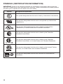
SYMBOLS
Safety Symbols
The purpose of safety symbols is to attract your attention to possible dangers. The safety
symbols and the explanations with them deserve your careful attention and understanding.
The symbol warnings do not, by themselves, eliminate any danger. The instructions and
warnings they give are no substitutes for proper accident prevention measures.
WARNING
Be sure to read and understand all safety instructions in this Owner’s
Manual, including all safety alert symbols such as “DANGER,”
“WARNING,” and “CAUTION” before using this tool. Failure to following all instructions listed
below may result in electric shock, re, and/or serious personal injury.
The denitions below describe the level of severity for each signal word. Please read the manual
and pay attention to these symbols.
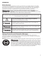
This is the safety alert symbol. It is used to alert you to potential
personal injury hazards. Obey all safety messages that follow this
symbol to avoid possible injury or death.
DANGER
DANGER indicates a hazardous situation which, if not avoided, will
result in death or serious injury.
WARNING
WARNING indicates a hazardous situation which, if not avoided, could
result in death or serious injury.
CAUTION
CAUTION, used with the safety alert symbol, indicates a hazardous
situation which, if not avoided, will result in minor or moderate injury.
Damage Prevention and Information Messages
These inform the user of important information and/or instructions that could lead to
equipment or other property damage if they are not followed. Each message is preceded by
the word “NOTICE”, as in the example below:
NOTICE: Equipment and/or property damage may result if these instructions are not followed.
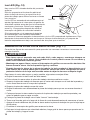
WARNING
The operation of any power tools can result in
foreign objects being thrown into your eyes, which
can result in severe eye damage. Before beginning power tool operation,
always wear safety goggles or safety glasses with side shields and a full
face shield when needed. We recommend a Wide Vision Safety Mask for
use over eyeglasses or standard safety glasses with side shields. Always
use eye protection which is marked to comply with ANSI Z87.1.

8
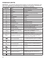
SYMBOLS (CONTINUED)
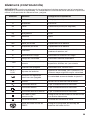
IMPORTANT: Some of the following symbols may be used on your tool. Please study them
and learn their meaning. Proper interpretation of these symbols will allow you to operate the
tool better and more safely.
Symbol Name Designation/Explanation
V Volts Voltage (potential)
A Amperes Current
Hz Hertz Frequency (cycles per second)
W Watt Power
kg Kilograms Weight
min Minutes Time
s Seconds Time
Wh Watt-hours Battery capacity
Ah Ampere-Hours Battery capacity
Ø Diameter Size of drill bits, grinding wheels, etc.
n
0
No load speed Rotational speed, at no load
n Rated speed Maximum attainable speed
…/min
Revolutions or reciprocation
per minute
Revolutions, strokes, surface speed,
orbits, etc. per minute
0 Off position Zero speed, zero torque...
1,2,3,…
I,II,III,
Selector settings
Speed, torque or position settings. Higher
number means greater speed
Innitely variable selector
with off
Speed is increasing from 0 setting
Arrow Action in the direction of arrow
Alternating current Type or a characteristic of current
Direct current Type or a characteristic of current
Alternating or direct current Type or a characteristic of current
Class II construction
Designates Double Insulated Construction
tools.
Earthing terminal Grounding terminal
Li-ion RBRC seal
Designates Li-ion battery recycling
program

9
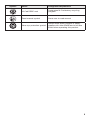
Symbol Name Designation/Explanation
Ni-Cad RBRC seal
Designates Ni-Cad battery recycling
program
Read manual symbol Alerts user to read manual
Wear eye protection symbol
Always wear safety goggles or safety
glasses with side shields and a full face
shield when operating this product.

10
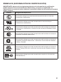
SYMBOLS (CERTIFICATION INFORMATION)
IMPORTANT: Some of the following symbols for certication information may be used on
your tool. Please study them and learn their meaning. Proper interpretation of these symbols
will allow you to operate the tool better and more safely.
Symbol Designation/Explanation
This symbol designates that this tool is listed by Underwriters Laboratories.
This symbol designates that this tool is recognized by Underwriters
Laboratories.
This symbol designates that this tool is listed by Underwriters
Laboratories, to United States and Canadian Standards.
This symbol designates that this tool is listed by the Canadian
Standards Association.
This symbol designates that this tool is listed by the Canadian
Standards Association, to United States and Canadian Standards.
This symbol designates that this tool is listed by the Intertek Testing
Services, to United States and Canadian Standards.
This symbol designates that this tool complies to NOM Mexican
Standards.

11
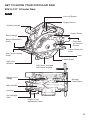
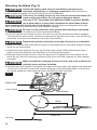
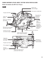
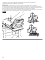
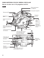
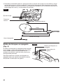
GET TO KNOW YOUR CIRCULAR SAW
20V 6-1/2’’ Circular Saw
Auxiliary Handle
Rip-Fence Locking
Knob
Bevel-Adjustment
Knob
Bevel Gauge
Saw-Line
Window
Depth-of-cut
Gauge
Main Handle
Hex key
Key Storage
Area
Extension
for Vacuum
Cleaner
Lock-off Button
Trigger Switch
Upper Guard
Lower-Guard Lift
Lever
Spindle-
Lock Button
Depth-of-cut
Adjustment Lever
Foot
Lower Guard
Rip Fence (included
with some models)
Fig. 1

12
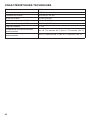
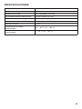
SPECIFICATIONS
Rated voltage 20V d.c.
No-load speed 4500 /min
Blade diameter 6-1/2’’ (165mm)
Blade arbor 5/8’’ (16mm)
Cutting depth at 90° 2-1/8’’ (54mm)
Cutting depth at 45° 1-3/4’’ (44.5mm)
Bevel range 0°~50°
Recommended working temperature 14 ~ 104°F (-10 ~ 40°C)
Recommended storage temperature 32 ~ 104°F (0 ~ 40°C)

13
OPERATING INSTRUCTIONS
WARNING
To reduce the risk of re, personal injury, and product damage due to
a short circuit, never immerse your tool, battery pack or charger in
uid or allow a uid to ow inside them. Corrosive or conductive uids, such as seawater,
certain industrial chemicals, and bleach or bleach-containing products, etc., can cause a
short circuit.
WARNING
If any parts are damaged or missing, do not operate this product until
the parts are replaced. Use of this product with damaged or missing
parts could result in serious personal injury.
WARNING
Do not attempt to modify this tool or create accessories not
recommended for use with this tool. Any such alteration or modication
is misuse and could result in a hazardous condition leading to possible serious injury.
WARNING
To prevent accidental starting that could cause serious personal
injury, always remove the battery pack from the tool when assembling
parts.
This cordless circular saw must be used only with the battery packs and charger listed
below:
Battery Pack
Charger
2Ah 4Ah 5Ah
SKIL BY519701 SKIL BY519601 SKIL BY519603 SKIL SC535801
NOTICE: Please refer to the battery pack and charger manuals for detailed operating
information.
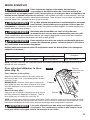
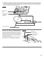
To Attach/Detach Battery Pack
(Fig. 2)
To attach the battery pack:
Align the raised rib on the battery pack with the
grooves of the tool, and then slide the battery
pack onto the tool.
NOTICE: Make sure that the latch on the
battery pack snaps into place and that the
battery pack is secured to the tool before
beginning operation.
To detach the battery pack:
Depress the battery-release button, located
on the front of the battery pack, to release the
battery pack. Pull the battery pack out and
remove it from the tool.
NOTICE: When placing the battery pack on the tool, be sure that the raised rib on the battery
pack aligns with the groove inside the tool and that the latches snap into place properly.
Improper attachment of the battery pack can cause damage to internal components.
WARNING
Battery tools are always in operating condition. Therefore, remove the
battery when the tool is not in use or when carrying it at your side.
Fig. 2
Attach
Detach
Battery-
Release Button

14
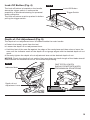
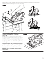
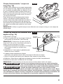
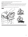
Attaching the Blade (Fig. 3)
WARNING
Detach the battery pack from the tool before performing any
assembly, adjustments, or changing accessories. Such preventive
safety measures reduce the risk of starting the tool accidentally.
WARNING
This tool is for cutting wood only. Use only the correct saw blades for
wood-cutting operations. Do not use any abrasive wheels.
WARNING
Use only 6-1/2’’ saw blade rated 4500/min (RPM) or greater. NEVER
use a blade that is so thick that it prevents the outer blade washer
from engaging with the at side of the spindle. Using a blade not designed for the saw
may result in serious personal injury and property damage.
WARNING
Be sure to wear protective work gloves while handling a saw blade.
The blade can injure unprotected hands.
a. Press the spindle-lock button and turn the hex key until the spindle-lock button engages.
The saw shaft is now locked. Continue to depress the spindle-lock button, turn the hex key
clockwise, and remove the blade bolt and the outer washer.
WARNING
Depress the spindle-lock button only when the tool is at a standstill.
b. Make sure that the saw teeth and the arrow on the blade point in the same direction as the
arrow on the lower guard.
c. Retract the lower guard all the way up into the upper guard. While retracting the lower
guard, check the operation and condition of the lower guard system.
d. Slide the blade through the slot in the foot and mount it against the inner washer on the
shaft. Be sure that the clamping surfaces of the inner and outer washers lay ush against
the blade.
WARNING
Make sure that the clamping surfaces of inner and outer washers are
perfectly clean and face the blade.
e. Reinstall the outer washer. First tighten the blade bolt nger tight, then tighten the blade bolt
1/8 turn (45°) with the hex key (this ensures slippage of the saw blade when it encounters
excessive resistance, thus reducing motor overload and saw kickback).
Fig. 3
Blade Shaft
Lower Guard
Hex key
Inner Washer
Blade
Outer Washer
Blade Bolt

15
Lock-Off Button (Fig. 4)
The lock-off button is located on the handle
above the trigger switch. It reduces the
possibility of accidental starting for personal
safety protection.
The lock-off button must be pushed in before
pulling the trigger switch.
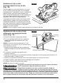
Depth-of-Cut Adjustment (Fig. 5)
The depth-of-cut adjustment lever is located beside the main handle.
a. Detach the battery pack from the tool.
b. Loosen the depth-of-cut adjustment lever.
c. Hold the foot of the saw at against the edge of the workpiece and then raise or lower the
saw until the indicator mark on the depth-of-cut gauge aligns with the desired depth-of-cut
mark.
d. Securely tighten the depth-of-cut adjustment lever at the desired depth-of-cut.
NOTICE: Check the depth-of-cut setting. Not more than one tooth length of the blade should
extend below the material to be cut, for minimum splintering.
Fig. 5
Indicator Mark
ONE TOOTH LENGTH
SHOULD PENETRATE WOOD
FOR MINIMUM SPLINTERING
Depth-of-cut
Adjustment Lever
Fig. 4
Lock-Off Button
Trigger Switch

16
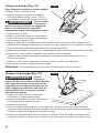
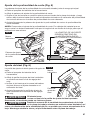
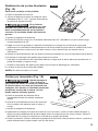
Bevel Adjustment (Fig. 6)
The bevel-adjustment knob adjusts the cutting
angle.
a. Detach the battery pack from the tool.
b. Loosen the bevel-adjustment knob by
rotating the knob counterclockwise.
c. Tilt the foot until the bevel-indicator mark
reaches the desired setting on the bevel
gauge.
d. Securely tighten the bevel-adjustment knob
by rotating the knob clockwise.
WARNING
Attempting to make bevel
cuts without the bevel-
adjustment knob securely tightened can
result in serious injury.
WARNING
Because of the increased amount of blade engagement in the work
while bevel cutting and decreased stability of the foot, blade binding
may occur. Keep the saw steady and the foot rmly on the workpiece.
NOTICE: When bevel cutting, the depth of cut does not correspond with value on the depth
of cut gauge.
NOTICE: Since the blade thicknesses vary and different angles require different settings,
always make a trial cut in scrap material along a guideline to determine how much you should
offset the guideline on the workpiece to be cut.
0° Bevel Check and Adjustment (Fig. 7)
Your tool has a 0° bevel stop, which has been adjusted before shipment to assure that the
blade is vertical to the foot at 0°bevel cutting.
To check and adjust to 0° Bevel:
a. Detach the battery pack from the tool.
b. Set the foot to the maximum depth-of-cut setting. Loosen the bevel-adjustment knob, set
the saw to 0° bevel on the bevel gauge, retighten the bevel-adjustment knob.
c. Turn the saw upside down and place it on a stable surface. Check for an angle of 90°
between the blade and the underside of the foot with a square.
d. If adjustment is necessary, loosen the bevel-adjustment knob. Place the saw in an upside-
down position on a workbench. Use a Philips-screwdriver to turn the 0° bevel-stop-
adjustment screw until the foot is square with the saw blade.
Fig. 7
Carpenter’s
Square
Blade
Foot
Bevel-Stop-
Adjustment Screw
Fig. 6
Indicator Mark
Bevel-
Adjustment
Knob

17
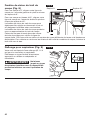
Saw-Line Window (Fig. 8)
For a 0° cut, align your line of cut with the left
notch in the foot at the 0° indicator.
For 45° bevel cuts, align your line of cut with
the right notch at the 45° indicator.
The saw-line window is also adjustable by
loosening the screw and realigning the window,
according to your need.
The saw-line window will give an approximate
line of cut. Make sample cuts in scrap lumber
to verify the actual line of cut. This will be
helpful because of the number of different
blade types and thicknesses available. To
ensure minimum splintering on the good side
of the material to be cut, face the good side
down.
Extension for Vacuum Cleaner
(Fig. 9)
Your tool is equipped with an extension (Ø1-
1/4’’) for connecting a vacuum cleaner.
Choose a suitable vacuum-cleaner hose or use
an adapter, if necessary.
WARNING
Never allow a vacuum-
cleaner hose interfere
with the lower guard or cutting operation.
Fig. 9
Fig. 8
0° Indicator
Screw
45° Indicator

18
LED Light (Fig. 10)
An LED light is located behind the upper guard.
This provides additional light on the saw blade
and the surface of the workpiece for operation
in lower-light areas.
The LED light will automatically turn on when
the trigger switch is pressed and will turn off
after the trigger switch is released.
If the tool and/or battery pack becomes
overloaded or too hot, the internal sensors will
turn the tool off, and the LED light will rapidly
ash. Rest the tool for a while or place the tool
and battery pack separately under air ow for
cooling.
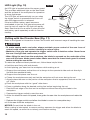
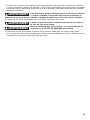
Cutting with the Circular Saw (Fig. 11)
Refer to the gures in this section to learn the correct and incorrect ways of handling the saw.
WARNING
•
To make sawing easier and safer, always maintain proper control of the saw. Loss of
control could cause an accident resulting in serious injury.
•
Maintain a rm grip and operate the trigger switch with a decisive action. Never force
the saw. Use light and continuous pressure.
•
When lifting the saw from the workpiece, the blade is exposed on the underside of the
saw until the lower blade guard closes. Make sure that the lower blade guard is closed
before setting the saw down.
To make the safest and best possible cut, follow these helpful hints:
a. Hold the saw rmly with both hands.
b. Avoid placing your hand on the workpiece while making a cut.
c. Support the workpiece so that the cut is always to the operator’s side and not directly in
line with the operator’s body.
d. Support the workpiece near the cut.
e. Clamp the workpiece securely so that the workpiece will not move during the cut.
f. Always place the saw on the portion of the workpiece that is supported, and not on the “cut
off” piece.
g. Place the workpiece with the “good” side down.
h. Draw a guideline along the desired cutting line before beginning the cut.
i. Rest the front edge of the foot on the workpiece without touching the blade to the
workpiece
j. Depress the trigger switch to start the saw.
k. Allow the blade to reach full speed, then guide the saw into the workpiece and make the
cut.
l. Release the trigger switch and allow the blade to come to a complete stop.
m.
Lift the saw from the workpiece.
NOTICE: Do not bind the blade in the cut.
When cutting is interrupted, to resume cutting: squeeze the trigger and allow the blade to
reach full speed, re-enter the cut slowly, and resume cutting.
Fig. 10
LED Light

19
When cutting across the grain, the bers of the wood have a tendency to tear and lift.
Advancing the saw slowly will minimize this effect.
Fig. 11
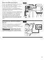
Cross-Cutting/Rip Cutting
(Fig. 12)
When making a cross-cut or a rip cut, align
the guideline with the 0˚ indicator notch on the
foot. The distance from the saw blade to the
saw base is approximately 1-3/8 in. (35mm) on
the left side of the saw and 4-1/6 in. (105mm)
on the right.
Blade thicknesses vary, so you should always
make a trial cut in scrap material along a
guideline to determine how much the guideline
must be offset from the guide to produce an
accurate cut.
NOTICE: Use a guide when making long or
wide rip cuts.
Fig. 12

20
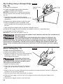
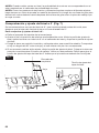
Rip Cutting Using a Straight Edge
(Fig. 13)
a. Secure the workpiece.
b. Clamp a straight edge to the workpiece
using C-clamps (not included).
NOTICE: Position the C-clamps so that they
will not interfere with the saw housing during
the cut.
c. Rest the front edge of the foot on the
workpiece without touching the blade to the
workpiece.
d. Depress the trigger switch to start the saw.
e. Allow the blade to reach full speed, then
guide the saw into the workpiece and make
the cut.
f. Saw along the straight edge to achieve a straight rip cut.
g. Release the trigger switch and allow the blade to come to a complete stop.
h. Lift the saw from the workpiece.
NOTICE: Do not bind the blade in the cut.
CAUTION
Always be sure that neither hand interferes with the free movement of
the lower guard.
CAUTION
After completing a cut and releasing the trigger, be aware of the
necessary time it takes for the blade to come to a complete stop
during coast down. Do not allow the saw to brush against your leg or side. Since the
lower guard is retractable, it could catch on your clothing and expose the blade. Be
aware of the necessary blade exposures that exist in both the upper and lower guard
areas.
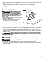
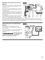
Bevel Cutting (Fig. 14)
To make the best possible cut:
a. Remove the battery from the saw.
b. Adjust the angle of cut to any desired setting
between 0° and 50°. Securely tighten the
bevel-adjustment knob.
WARNING
Attempting a bevel cut
without having the bevel-
adjustment knob securely locked in place
can result in serious injury.
c. Attach the battery pack
d. Align the cutting line with the 45° indicator
notch on the foot when making 45° bevel
cuts.
e. Make a trial cut in scrap material along a guideline to determine the amount to offset the
guideline on the cutting material.
f. Hold the saw rmly with both hands, as shown.
g. Rest the front edge of the foot on the workpiece without touching the blade to the
workpiece.
h. Depress the trigger switch to start the saw.
Fig. 14
Fig. 13
Desired Line
of Cut
Straight Edge
La page est en cours de chargement...
La page est en cours de chargement...
La page est en cours de chargement...
La page est en cours de chargement...
La page est en cours de chargement...
La page est en cours de chargement...
La page est en cours de chargement...
La page est en cours de chargement...
La page est en cours de chargement...
La page est en cours de chargement...
La page est en cours de chargement...
La page est en cours de chargement...
La page est en cours de chargement...
La page est en cours de chargement...
La page est en cours de chargement...
La page est en cours de chargement...
La page est en cours de chargement...
La page est en cours de chargement...
La page est en cours de chargement...
La page est en cours de chargement...
La page est en cours de chargement...
La page est en cours de chargement...
La page est en cours de chargement...
La page est en cours de chargement...
La page est en cours de chargement...
La page est en cours de chargement...
La page est en cours de chargement...
La page est en cours de chargement...
La page est en cours de chargement...
La page est en cours de chargement...
La page est en cours de chargement...
La page est en cours de chargement...
La page est en cours de chargement...
La page est en cours de chargement...
La page est en cours de chargement...
La page est en cours de chargement...
La page est en cours de chargement...
La page est en cours de chargement...
La page est en cours de chargement...
La page est en cours de chargement...
La page est en cours de chargement...
La page est en cours de chargement...
La page est en cours de chargement...
La page est en cours de chargement...
La page est en cours de chargement...
La page est en cours de chargement...
La page est en cours de chargement...
La page est en cours de chargement...
La page est en cours de chargement...
La page est en cours de chargement...
La page est en cours de chargement...
La page est en cours de chargement...
La page est en cours de chargement...
La page est en cours de chargement...
La page est en cours de chargement...
La page est en cours de chargement...
La page est en cours de chargement...
La page est en cours de chargement...
La page est en cours de chargement...
La page est en cours de chargement...
-
 1
1
-
 2
2
-
 3
3
-
 4
4
-
 5
5
-
 6
6
-
 7
7
-
 8
8
-
 9
9
-
 10
10
-
 11
11
-
 12
12
-
 13
13
-
 14
14
-
 15
15
-
 16
16
-
 17
17
-
 18
18
-
 19
19
-
 20
20
-
 21
21
-
 22
22
-
 23
23
-
 24
24
-
 25
25
-
 26
26
-
 27
27
-
 28
28
-
 29
29
-
 30
30
-
 31
31
-
 32
32
-
 33
33
-
 34
34
-
 35
35
-
 36
36
-
 37
37
-
 38
38
-
 39
39
-
 40
40
-
 41
41
-
 42
42
-
 43
43
-
 44
44
-
 45
45
-
 46
46
-
 47
47
-
 48
48
-
 49
49
-
 50
50
-
 51
51
-
 52
52
-
 53
53
-
 54
54
-
 55
55
-
 56
56
-
 57
57
-
 58
58
-
 59
59
-
 60
60
-
 61
61
-
 62
62
-
 63
63
-
 64
64
-
 65
65
-
 66
66
-
 67
67
-
 68
68
-
 69
69
-
 70
70
-
 71
71
-
 72
72
-
 73
73
-
 74
74
-
 75
75
-
 76
76
-
 77
77
-
 78
78
-
 79
79
-
 80
80


Skil CR540601 Le manuel du propriétaire
- Catégorie
- Outils électroportatifs
- Taper
- Le manuel du propriétaire
dans d''autres langues
- English: Skil CR540601 Owner's manual
- español: Skil CR540601 El manual del propietario
Documents connexes
Autres documents
-
SKILSAW SPTH77M-12 Manuel utilisateur
-
Ferm CSM1049 20V Cordless Circular Saw Manuel utilisateur
-
Bosch 1671K Mode d'emploi
-
Bosch Power Tools CCS180B Manuel utilisateur
-
-
-
-
Genesis GLCS2055A Manuel utilisateur
-
Worx WX520L 20V Cordless Brushless Circular Saw Le manuel du propriétaire
-
Ryobi EWS1150RS Le manuel du propriétaire