Ingersoll Rand 80445703 Stationary Reciprocating Air Compressors Manuel utilisateur
- Catégorie
- Compresseurs d'air
- Taper
- Manuel utilisateur
Ce manuel convient également à

80445703
Revision H
March 2018
Save These Instructions
Permanently Installed Stationary
Reciprocating Air Compressors
Quick Start Manual
Manual inicio rápido
ES
Guide de démarrage rapide
FR
Quick Start Manual
EN
RELEASED 05/Apr/2018 15:16:08 GMT
PRINT LANGUAGE
ENGLISH
FRENCH
SPANISH

EN-2 80445703 Rev. H
CONTENTS
CONTENTS .....................................................EN-2
WARRANTY & PRODUCT REGISTRATION . . . . . . . . . . . . . . . . . . . . . . . . . EN-2
EXPLANATION OF SAFETY SIGNAL WORDS . . . . . . . . . . . . . . . . . . . . . . EN-2
RECEIPT & INSPECTION .........................................EN-2
GENERAL SAFETY RULES........................................EN-3
SELECTING A LOCATION ........................................EN-3
MOUNTING ....................................................EN-4
AIR INLET CONNECTIONS .......................................EN-5
AIR DISCHARGE CONNECTIONS .................................EN-5
ELECTRICAL CONNECTIONS.....................................EN-5
COMPRESSOR LUBRICATION ....................................EN-8
OPERATION ....................................................EN-8
USING THE QR CODE............................................EN-9
MATERIAL SAFETY DATA - ALL SEASON SELECT . . . . . . . . . . . . . . . . .EN-10
WARRANTY & PRODUCT REGISTRATION
For Warranty and Limitation of Liability, please refer to your Operators
Manual, available at www.IRrecip.com”.
To register your product with an Extended Warranty Kit, go to www.
IRrecip.com/registration in your Web browser. Otherwise, you must
contact your local full service air solutions provider.
To locate your nearest provider:
1. Go to http://www.ingersollrandproducts.com in your Web
browser.
2. Select Americas Region from main page.
3. Click “Customer Service”.
4. Click “Contact Us”.
5. Click “Compressed Air Solutions”.
6. If you are located in the United States, enter your 5-digit zip code
in the eld to nd your local full service air solutions provider
and then press “Search on Zip Code”. If you are located outside
of the United States, select your country from the “International
Locations” list and then press “Submit”.
EXPLANATION OF SAFETY SIGNAL WORDS
DANGER
Indicates an imminently hazardous
situation which, if not avoided, will
result in death or serious injury.
WARNING
Indicates a potentially hazardous
situation which, if not avoided, could
result in death or serious injury.
CAUTION
Indicates a potentially hazardous
situation which, if not avoided, may
result in minor or moderate injury or
property damage.
NOTICE
Indicates information or a company
policy that relates directly or indirectly
to the safety of personnel or protection
of property.
RECEIPT & INSPECTION
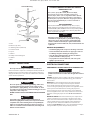
Ensure adequate lifting equipment is available for unloading and
moving the compressor to the installation site.
WARNING
Lifting equipment must be properly rated for the weight of the
compressor. Weight information is printed on a label attached to
the shipping container.
Lift the compressor by the shipping skid only.
Do not use the motor lifting eye to lift the entire compressor. The
motor lifting eye is for removing the motor from the compressor
only.
Do not work on or walk under the compressor while it is
suspended.
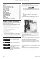
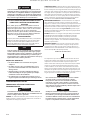
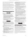
Use suitable lifting equipment (i.e. forklift) to lift and transport the
compressor to the installation site. Ensure the lifting equipment,
straps, etc. are capable of supporting the weight of the compressor.
Lifting Equipment and Straps
Before signing the delivery receipt, inspect for damage and missing
parts. If damage or missing parts are apparent, make the appropriate
notation on the delivery receipt, then sign the receipt. Immediately
contact the carrier for an inspection.
All material must be held in the receiving location for the carrier’s
inspection.
Delivery receipts that have been signed without a notation of damage
or missing parts are considered to be delivered “clear.” Subsequent
claims are then considered to be concealed damage claims. Settle
damage claims directly with the transportation company.
If you discover damage after receiving the compressor (concealed
damage), the carrier must be notied within 15 days of receipt and
an inspection must be requested by telephone with conrmation in
writing. On concealed damage claims, the burden of establishing that
the compressor was damaged in transit reverts back to the claimant.
Read the compressor nameplate to verify it is the model ordered, and
read the motor nameplate to verify it is compatible with your electrical
conditions.
Make sure electrical enclosures and components are appropriate for
the installation environment.
Do not use a triple voltage three-phase motor for 200-208 voltage
three phase application. Use a 200 volt motor only.
•
•
•
•
RELEASED 05/Apr/2018 15:16:08 GMT

80445703 Rev. H EN-3
GENERAL SAFETY RULES
DANGER
INHALATION HAZARD. Will cause serious injury or death.
Can contain carbon monoxide or other contaminants.
Ingersoll Rand air compressors are not designed, intended,
or approved for breathing air applications. Ingersoll Rand
does not approve specialized equipment for breathing air
application and assumes no responsibility or liability for
compressors used for breathing air services.
Do not directly inhale compressed air.
Follow precautions on container labels before spraying
materials such as paint, insecticide and weed killer.
Wear a respirator when spraying.
WARNING
FLAMMABLE VAPORS. Can cause a re or explosion and result in
serious injury or death.
Do not operate electric motor driven compressors where
ammable or explosive liquids or vapors such as gasoline,
natural gas and solvents are present.
Do not operate gasoline engine driven compressors near an
open ame.
HAZARDOUS VOLTAGE. Can cause serious injury or death.
Disconnect power and relieve pressure from tank before
servicing.
Compressor must be connected to properly grounded circuit
by a qualied electrician following applicable electrical
codes. Refer to the ELECTRICAL CONNECTIONS section of this
manual.
Do not operate compressor in wet conditions. Store indoors.
MOVING PARTS. Can cause serious injury.
Do not operate with guards or shields removed, damaged or
broken.
Machine may start automatically. Disconnect power before
servicing.
HOT SURFACES. Can cause serious injury. Burns may occur.
Do not touch the compressor pump, motor or discharge
tubing during or shortly after operation. These parts become
hot. Allow to cool before touching.
HIGH PRESSURE AIR. Can cause serious injury.
Do not remove, adjust, bypass, change, modify or make
substitutions for safety/relief valves or other pressure control
related devices.
Rusted tanks can cause explosion and severe injury or death.
Drain tank daily or after each use. Drain valve located at
bottom of tank.
Do not over-pressurize the receiver tank or similar vessels
beyond design limits. Refer to compressor nameplate for this
information.
Do not use a receiver tank or similar vessels that fail to meet
the design requirements of the compressor. Contact your
distributor for assistance.
Do not drill into, weld or otherwise alter the receiver tank or
similar vessels.
Do not use air tools or attachments without rst determining
the maximum pressure recommended for that equipment.
Do not point air nozzles or sprayers toward anyone.
RISK OF BURSTING. Can cause serious injury.
•
•
•
•
•
•
•
•
•
•
•
•
•
•
•
•
•
•
•
•
•
Use only suitable air handling parts acceptable for pressure
of not less than the maximum allowable working pressure
of the machine. Refer to compressor nameplate for this
information.
FLYING DEBRIS. Can cause serious injury to eyes.
Wear eye protection at all times.
NOISE HAZARD. Can cause serious injury to ears.
Wear ear protection at all times.
NOTICE
Do not remove, paint over or deface decals. Replace any missing
decals.
SELECTING A LOCATION
ELECTRIC MOTOR COMPRESSORS
For most electric motor compressors, select a relatively clean and dry
well lighted indoor area with plenty of space for proper ventilation,
cooling air ow and accessibility. Provide 1,000 cubic feet of fresh air
per minute per 5 horsepower. Ventilation by gravity or mechanical
means is approved. Locate the compressor at least 12 inches (30 cm)
from walls, and make sure the main power supply is clearly identied
and accessible.
Unless the electrical components of the compressor are specially
protected for outdoor use, do not install an electric motor compressor
outdoors or in an area that will expose the electrical components to
rain, snow or sources of appreciable moisture.
WARNING
FOR COMPRESSORS EQUIPPED WITH ELECTRIC DRAIN VALVES
The electric drain valve incorporates arcing or sparking parts,
such as snap switches, receptacles and the like that tend to
produce arcs or sparks and, therefore, when located in a garage,
the compressor should be in a room or enclosure provided for
the purpose, or the electric drain valve should be 18 inches (45
cm) or more above the oor. To relocate the valve, contact your
local Ingersoll Rand dealer to obtain an electric drain valve
relocation kit.
GASOLINE ENGINE COMPRESSORS
For gasoline engine compressors, keep the engine at least 3 feet (1 m)
away from building walls and other equipment. Install the compressor
in a location with plenty of space for proper ventilation, cooling air
ow and accessibility. Do not install or operate a gasoline engine
compressor in a conned area.
AMBIENT TEMPERATURE CONSIDERATIONS
Ideal operating temperatures are between 32°F and 100°F (0°C and
37.8°C). If temperatures consistently drop below 32°F (0°C), install the
compressor in a heated area. If this is not possible, you must protect
safety/relief valves and drain valves from freezing. If temperatures
are consistently below 40°F (4.4°C), consider installing an external
crankcase heater kit, especially if the compressor has diculty starting.
CAUTION
Never operate the compressor in temperatures below -15°F
(-26.1°C) or above 125°F (51.0°C).
HUMID AREAS
In frequently humid areas, moisture may form in the pump and
produce sludge in the lubricant, causing running parts to wear out
prematurely. Excessive moisture is especially likely to occur if the
compressor is located in an unheated area that is subject to large
temperature changes.
•
•
•
RELEASED 05/Apr/2018 15:16:08 GMT

EN-4 80445703 Rev. H
Two signs of excessive humidity are external condensation on the
pump when it cools down and a “milky” appearance in petroleum
lubricant.
You may be able to prevent moisture from forming in the pump by
increasing ventilation, operating for longer intervals or installing an
external crankcase heater kit.
NOISE CONSIDERATIONS
Consult local ocials for information regarding acceptable noise levels
in your area. To reduce excessive noise, use vibration isolator pads or
intake silencers, relocate the compressor or construct total enclosures
or bae walls.
MOUNTING
WARNING
Remove the compressor from the skid before mounting.
Refer to the RECEIPT & INSPECTION section of this manual for
information on lifting and handling the compressor.
NOTICE
Local codes may mandate specic mounting requirements
including, but not limited to, the use of vibration isolation
mounts or pads. Mounting kits including vibration isolation
mounts or pads may be ordered through your Ingersoll Rand
dealer if not included with the compressor. Consult your local
Ingersoll Rand dealer for more information.
Secure the compressor to a solid, at and level mounting
surface.
If vibration isolation mounts or pads are included with your
compressor, they must be properly installed. Failure to install
the compressor using the vibration isolation mounts or pads
provided with the compressor and in accordance with the
installation instructions may result in mechanical failure to
the compressor and cancellation of warranty coverage.
Do not install the compressor on I-beams, open-grid ooring
systems, or non-solid surfaces.
Ingersoll Rand shall bear no responsibility for equipment
installed on non-approved vibration isolation mounts or pads
or non-solid surfaces.
CONCRETE FLOORS ELECTRIC MOTOR
OR GASOLINE ENGINE POWERED
COMPRESSORS
NOTICE
Mounting hardware kit 46822243 is available for mounting 3-
footed vertical tank compressors to concrete oors.
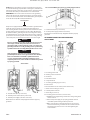
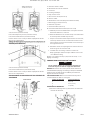
To mount the compressor to a concrete surface, use the following
procedure:
Mark the location of the mounting holes.
Drill 2-1/4” deep holes using a concrete drill bit sized per the
following table.
Tank Size
(Gal.) Drill Bit
Size (In.)
≤ 120 1/2
≥ 240 5/8
•
•
•
•
•
1)
2)
NOTICE
It may be helpful to use a piece of tape on the drill bit to mark
the proper depth.
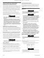
3) Drill a hole through the center of each isolation pad (if supplied
or mandated by local codes).
4) Drive the anchors into the mounting holes with the threaded
portion up.
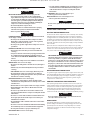
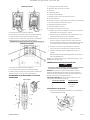
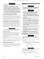
5) Place the isolation pads over the anchors as shown in the
illustration below.
6) Position the compressor over the drilled holes and slowly lower
the compressor feet over the holes.
7) Install the foundation bolts.
8)
Install the nuts and torque each in a criss-cross pattern to 10 ft. lb.
Typical Mounting
A = Mounting surface
B = Foundation bolt / anchor
C = Isolation pad (if supplied or required by local codes)
D = Compressor mounting foot
E = Washer
F = Nut
After all mounting nuts are installed, check for receiver stress by
loosening each nut individually to check for upward movement
of the foot. Upward movement indicates the requirement for an
appropriately sized metal shim to ll in the open elevation under the
foot. After all required shims have been inserted, re-tighten the nuts
to 10 ft. lb.
Do not secure uneven feet tightly, as this will cause excessive stress on
the receiver tank.
TRUCK BEDS GASOLINE ENGINE POWERED
COMPRESSORS ONLY
NOTICE
Mounting hardware kit 46821641 is available for mounting
gasoline engine compressors to truck beds .
Gasoline engine compressors mounted on truck beds must be
fastened securely without applying excessive stress on the receiver
tank. Follow the general instructions for concrete oor installation in
this section using appropriate mounting hardware.
RELEASED 05/Apr/2018 15:16:08 GMT

80445703 Rev. H EN-5
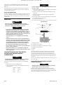
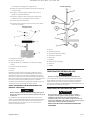
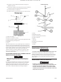
Truck Bed Mounting
A = Nut
B = Washer (3 per foot)
C = Mounting surface (truck bed)
D = Isolation mount
E = Spacer
F = Washer
G = Compressor mounting foot
H = Washer
J = Bolt
AIR INLET CONNECTIONS
CAUTION
Do not operate the compressor without air inlet ltration.
If the air around the compressor is relatively free of dirt, install the air
inlet lter(s) at the inlet connection(s) at the compressor. If the air is
dirty, pipe the lter(s) to a source of clean air. Refer to the manual for
remote air inlet requirements.
AIR DISCHARGE CONNECTIONS
WARNING
Do not use plastic pipe, soldered copper ttings, rubber hose,
or lead-tin soldered joints anywhere in the compressed air
system. All hoses, piping, ttings, air receiver tanks, etc. must
be certied safe for at least the maximum working pressure and
temperature of the compressor.
DO NOT USE PVC PLASTIC IN THE COMPRESSED AIR DISCHARGE
LINE.
CAUTION
If you will be using synthetic compressor lubricant, all
downstream piping material and system components must be
compatible. Refer to the following material compatibility list.
If there are incompatible materials present in your system, or
if there are materials not included in the list, contact Ingersoll
Rand for recommendations.
SYNTHETIC COMPRESSOR LUBRICANT MATERIAL
COMPATIBILITY LIST
SUITABLE
Viton®, Teon®, Epoxy (Glass Filled), Oil Resistant Alkyd,
Fluorosilicone, Fluorocarbon, Polysulde, 2-Component
Urethane, Nylon, Delrin®, Celcon®, High Nitrile Rubber (Buna N.
NBR more than 36% Acrylonitrile), Polyurethane, Polyethylene,
Epichlorohydrin, Polyacrylate, Melamine, Polypropylene, Baked
Phenolics, Epoxy, Modied Alkyds (® indicates trademark of
DuPont Corporation)
NOT RECOMMENDED
Neoprene, Natural Rubber, SBR Rubber, Acrylic Paint, Lacquer,
Varnish, Polystyrene, PVC, ABS, Polycarbonate, Cellulose Acetate,
Low Nitrile Rubber (Buna N. NBR less than 36% Acrylonitrile), EPDM,
Ethylene Vinyl Acetate, Latex, EPR, Acrylics, Phenoxy, Polysulfones,
Styrene Acrylonitrile (San), Butyl
NOTICE
All compressed air systems generate condensate which
accumulates in any drain point (e.g. tanks, lters, drip legs,
aftercoolers, dryers). This condensate contains lubricating
oil and/or substances which may be regulated and must be
disposed of in accordance with local, state, and federal laws and
regulations.
GENERAL REQUIREMENTS
Use exible piping at the compressor’s discharge connection.
Use hard-welded or threaded steel or copper pipes and cast
iron ttings along the remaining air discharge line.
Slope the piping downward in the direction of airow to
permit condensate to drain properly.
Use pipe thread sealant on all threads, and secure joints
tightly to prevent air leaks.
ELECTRICAL CONNECTIONS
PERMANENTLY CONNECTED ELECTRIC COMPRESSORS
WARNING
Electrical installation and service must be performed by a
qualied electrician who is familiar with all applicable electrical
codes.
GENERAL. The motor rating, as shown on the motor nameplate, and
the power supply must have compatible voltage, phase and hertz
characteristics.
WIRE SIZE. The electrical wiring between the power supply and
electric motor varies according to motor horsepower and other
factors. Install adequately sized power leads to protect against
excessive voltage drop during start-up. Refer to the applicable electric
codes in your area for information on selecting the proper wire
size and securing electrical connections. If you connect additional
electrical equipment to the same circuit, consider the total electrical
load when selecting the proper wire size. DO NOT USE UNDERSIZE
WIRE.
MAGNETIC STARTER. If the motor installed on your compressor has
a motor reset button, it does not require a magnetic starter. If the
motor does not have this button and the compressor does not have
a factory-installed starter, install a magnetic starter with thermal
overload protection. Follow the manufacturer’s instructions for
installation. Ingersoll Rand cannot accept responsibility for damages
arising from failure to provide adequate motor protection.
•
•
•
•
RELEASED 05/Apr/2018 15:16:08 GMT

EN-6 80445703 Rev. H
FUSES. Refer to applicable local codes to determine the proper fuse
or circuit breaker rating required. When selecting fuses, remember the
momentary starting current of an electric motor is greater than its full
load current. Time delay or “slow-blow” fuses are recommended.
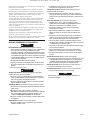
GROUNDING. In the event of an electrical short circuit, grounding
reduces the risk of electric shock by providing an escape wire for the
electric current. Ground terminals are identied with a ground symbol
and/or the letters “G”, “GR” or “PE” (Potential Earth).
Ground Symbo
l
Compressors equipped with motor starters include a ground terminal
inside the starter enclosure. For compressors with single-phase
motors having thermal overload protection and no motor starter, the
ground terminal is located inside the pressure switch. Ground must
be established with a grounding wire sized according to the voltage
and minimum branch circuit requirements printed on the compressor
specications decal. Ensure good bare metal contact at all grounding
connection points, and ensure all connections are clean and tight.
WARNING
Improper grounding can result in electrical shock and can cause
severe injury or death. This product must be connected to a
grounded, metallic, permanent wiring system or an equipment-
grounding terminal or lead. All grounding must be performed by
a qualied electrician and comply with applicable electric codes.
NOTICE
Verify grounding connections after initial installation and
periodically thereafter to ensure good contact and continuity
has been maintained. Consult with a qualied electrician
or service technician if the grounding instructions are not
completely understood, or if in doubt as to whether the product
is properly grounded.
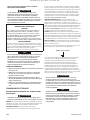
Starter wiring
A – To/from motor (factory connection)
B – To/from pressure switch (factory connection)
C – To/from power supply (customer connection)
Ground wires not shown for clarity. Equipment must be properly
grounded.
Pressvre Switch Wiring (For Compressors Not Requiring a Starter)
A – To/from motor (factory connection)
B – To/from power supply (customer connection)
Ground wires not shown for clarity. Equipment must be properly
grounded.
IEC POWER CONNECTION AND OVERLOAD
ADJUSTMENT
IEC Connection
A = Incoming power leads
B = Existing control circuit wires
C = Contactor
D = Thermal overload
E = Stop/test button
F = Incoming grounding lug (see note 2)
G = Motor leads
H = Reset button & selector switch (set for manual reset)
J = Motor current setting (see note 5)
K = Switch position indicator
L = Coil voltage (see note 1)
M = Incoming power connection (see notes 3 & 4)
1. Conrm that the supply voltage matches the voltage rating of the
starter/contactor.
2. Connect the power supply to a properly grounded electrical
circuit with specied voltage and fuse protection.
3. When connecting the incoming power wires to the contactor,
ensure that the existing control circuit wires remain under the
terminal pressure plates and are secure after tightening the
screw terminals.
RELEASED 05/Apr/2018 15:16:08 GMT

80445703 Rev. H EN-7
4. Refer to the torque values listed on side of the contactor when
tightening the wire terminal screws.
5. The overload current setting formula is as follows:
Motor Nameplate Amps X Motor Service Factor = Overload
Setting
Example: 10.0 (Motor Amps) x 1.15 (Service Factor) = 11.50 Overload
Setting
GASOLINE ENGINE COMPRESSORS
NOTICE
If you will be making connections to a remote battery, the
engine on the compressor must be equipped with an alternator.
BATTERY. A 12 volt battery with a minimum current rating of 250
CCA (cold cranking amps) and minimum ampere-hour rating of 24 Ah
should be sucient for cranking most electric start engines.
BATTERY CABLES. Refer to the following table for size and length
recommendations.
Cable Size (GA) Maximum Length
6 5’ (1.5 m.)
4 7’-2.5” (2.1 m.)
2 12’ (3.6 m.)
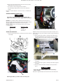
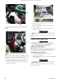
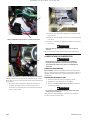
CONNECTION PROCEDURES:
Connect the battery positive (+) cable (A) to the starter solenoid
terminal (B).
B
D
Kohler Engine Battery (+) Positive cable connection point
1)
B
D
Honda Engine Battery (+) Positive cable connection point.
NOTE: Circuit Fuse location at (D). Electric Start will not work if Fuse is
blown. Unit can be rope started, however will not charge the Battery if
Fuse is blown.
2) Connect the battery negative (-) cable (C) to the bolt shown in
the following illustration. Secure the wire in place by screwing a
suitably-sized nut onto the bolt and down onto the terminal.
3) Connect the battery positive (+) cable (A) to the battery positive
(+) terminal.
4) Connect the battery negative (-) cable (C) to the battery negative
(-) terminal.
5) Coat the terminals and cable ends with corrosion-preventive
grease.
WARNING
Remove the cable from the negative (-) side of the battery
before servicing.
Refer to the engine manufacturer’s instructions for more information.
RELEASED 05/Apr/2018 15:16:08 GMT

EN-8 80445703 Rev. H
COMPRESSOR LUBRICATION
CAUTION
Do not operate without lubricant or with inadequate lubricant.
Ingersoll Rand is not responsible for compressor failure caused
by inadequate lubrication.
RECOMMENDED LUBRICANT
Ingersoll Rand recommends All Season Select® synthetic lubricant
from startup. If you decide to use an alternate lubricant, refer to the
main owner’s manual for specications.
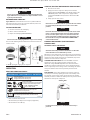
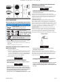
FILLING PROCEDURES
Unscrew and remove the oil ll plug.
Fill the crankcase with lubricant.
Replace the oil ll plug HAND TIGHT ONLY.
CAUTION
Do not remove the oil ll plug while the compressor is running.
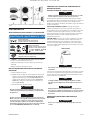
Use one of the following methods illustrated to determine when the
crankcase is full.
A = Oil ll opening, B = Sight glass, C = Dipstick
OPERATION
DAILY PREOPERATION CHECKS
MAINTENANCE / MANTENIMIENTO / ENTRETIEN
56258809-01
= ADD - AGREGAR - AJOUTER
= FULL - LLENO - PLEIN
• Consult instruction manual for more detail.
• Ver el manual de instrucciones para mas detalles.
• Pour de plus amples informations, consulter le manuel
d’instruction.
• Drain air tank daily.
• Drenar el tanque de aire una vez al dia.
• Purgez le réservoir d’air tous les jours.
• Clean air filter monthly.
• Verificar el estado del filtro de aire una ves por mes.
• Nettoyez le filtre à air chaque mois.
• Check oil level weekly.
• Verificar el nivel de aceite una vez por semana.
• Contrôlez le niveau d'huile chaque semaine.
Drain condensate from air tank
Check oil level(s) of compressor and engine (if applicable)
Check cleanliness of air lter(s)
1)
2)
3)
•
•
•
STARTUP ELECTRIC MOTOR DRIVEN COMPRESSORS
Close the service valve.
Apply power to the compressor. If the pressure switch is
equipped with an “ON/AUTO-OFF” lever, ip the switch to the
“ON/AUTO” position. If the compressor is equipped with a
control panel “ON/OFF” switch, move the switch to the “ON”
position.
Slowly open the service valve.
CAUTION
Unusual noise or vibration indicates a problem. Do not continue
to operate until you identify and correct the source of the
problem.
NOTICE
Ensure the direction of rotation is correct per the arrow on the
motor or on the beltguard above the motor. If the rotation is
incorrect on three phase compressors, disconnect the main
power and contact a qualied electrician to interchange any
two of the three leads per the ELECTRICAL CONNECTIONS
section of this manual.
COMPRESSOR CONTROLS ELECTRIC MOTOR
COMPRESSORS
AUTOMATIC START & STOP CONTROL.
NOTICE
Automatic Start & Stop Control is intended for use when the
motor will start no more than 6 times per hour.
When the receiver tank pressure reaches the factory preset maximum
pressure, the pressure switch stops the compressor. When the receiver
tank pressure drops below the factory preset minimum, the pressure
switch resets and restarts the compressor.
STANDARD PRESSURE SWITCH. The Standard NEMA-1 Pressure
Switch is Pre-set at the required pressures and the range and
dierential settings ARE NOT adjustable. These Pressure Switches
should not be tampered with in any way and no attempt should be
made to adjust the pressure settings as this could damage the Switch
to the point of failure and/or void any warranty for the Pressure
Switches.
DUAL CONTROL. Select either automatic start and stop control or
constant speed control by adjusting the knob on the auxiliary valve.
For automatic start and stop control, turn the knob on the auxiliary
valve fully clockwise to disable the auxiliary valve. The pressure switch
will then start and stop the compressor.
Auxillary Valve
Auxiliary Valve
NOTICE
For dual control compressors, automatic start and stop is
preferred.
1)
2)
3)
RELEASED 05/Apr/2018 15:16:08 GMT

80445703 Rev. H EN-9
Select constant speed control if the compressor restarts in less than 10
minute intervals or runs more than 40 minutes per hour. Turn the knob
fully counterclockwise to run the compressor continually.
NOTICE
The auxiliary valve is factory preset at 5 PSIG lower than the
factory pressure switch setting.
CAUTION
Running unloaded for more than 20 minutes per hour or more
than 15 minutes continually with the use of constant speed
control will cause oil pumping and should be avoided.
STARTUP GASOLINE ENGINE COMPRESSORS
WARNING
Do not operate gasoline engine compressors in an enclosed
area.
Release any residual tank pressure by slowly opening the
manual drain valve.
Turn on the engine gasoline supply.
Put the choke in the “on” position.
Close the service valve and put the unloader lever in the
“unload” (A) position.
Unloader
Unloader
5) Start the engine, release the choke, and allow the engine to
warm up for two to three minutes.
6) Return the unloader lever to the “load” (B) position.
NOTICE
Turn the gasoline supply o when the compressor is not being
used.
NOTICE
Some gasoline engine driven compressors require 5-8 break-in
hours of operation before reaching full capacity and speed.
COMPRESSOR CONTROLS GASOLINE ENGINE
COMPRESSORS
CONSTANT SPEED CONTROL. This type of control applies to gasoline
engine compressors.
When the receiver tank pressure reaches the factory preset maximum
pressure, the unloader slows down the engine and the compressor
stops pumping. When the receiver tank pressure drops to the factory
preset minimum, the unloader resets, the engine returns to full speed,
and the compressor resumes pumping.
1)
2)
3)
4)
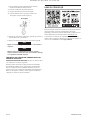
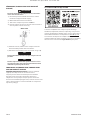
USING THE QR CODE
Scan QR code located on compressor to download detailed
installation, operation, maintenance, troubleshooting and repair parts
information not covered in this manual. More information is available
at www.IRrecip.com.
If Quick Start Manual or QR code label are damaged, and you wish
to order paper copies of any of the documents, contact your local
Ingersoll Rand dealer.
RELEASED 05/Apr/2018 15:16:08 GMT

EN-10 80445703 Rev. H
MATERIAL SAFETY DATA ALL SEASON SELECT®
Eective Date: 01/01/2011
ALL SEASON SELECT is a diester based synthetic lubricant formulated
for use in Ingersoll Rand reciprocating air compressors.
1. PRODUCT IDENTIFICATION:
Mixture-Chemical Family: Diester
2. HAZARDOUS INGREDIENTS:
The components of this product are not listed as hazardous or toxic
according to OSHA (29 CFR OSHA 1910.1200), NTP, IARC and SARA 313.
Hazardous Materials Identication System (HMIS):
Health Flammability Reactivity Basis Hazard Ratings Key:
0 1 0 - 4 = Highest 0 = Lowest
3. PHYSICAL DATA:
Boiling Point: N/A Pour Point: -40°F
Viscosity: 96.9 cSt @ 40°C Specic Gravity: 0.92
Vapor Density: Greater than air Percent Volatile: Negligible
Solubility in Water: Negligible
Evaporation Rate: Not volatile, slower than Butyl
Appearance: Light straw coloured uid Acetrate
Odor: Mild ester odor
4. FIRE AND EXPLOSION HAZARD DATA:
Flash Point: 480°F (249°C) Method Used: ASTM D92
Flammable Limits: Not established
Fire Fighting Media: Water spray, dry chemical, foam or carbon dioxide
Fire Fighting Procedures: Use water to keep re-exposed container
cool.
Wear self-contained positive pressure breathing apparatus and full
protective gear to ght re. Cool with water spray.
Special Fire and Explosion Hazard: None expected
5. HEALTH HAZARD:
This product does not contain any components considered to be
health hazards under the OSHA Hazard Communication Standards
29CFR 1910.1200 or under the WHMIS Controlled Product Regulations
in Canada.
Eects on exposure: Prolonged or repeated skin contact may tend
to remove natural skin oils, thus leading to possible irritation and
dermatitis. Medical Conditions Generally Aggravated by Exposure:
May aggravate previous skin condition.
Skin Contact: With repeated contact, a skin defatter. May develop
redness or mild irritation.
Skin Absorption: Not established
Ingestion (Acute): Can cause gastrointestinal irritation. No hazard
expected in normal use.
Eyes: Mild irritation.
Systemic & Other Eects: Not established
6. REACTIVITY DATA:
Stability: Stable under normal storage conditions
Incompatibility: Avoid contact with strong oxidizers such as liquid
chlorine, concentrated oxygen, sodium hypochlorite or calcium
hypochlorite.
Hazardous Decomposition: Burning will produce toxic fumes.
Hazardous Polymerization: Will not occur under normal conditions
Conditions to Avoid: Open ames
7. HANDLING AND STORAGE:
Exposure Guidelines: Not Established. OSHA TLV/TWA 5mg/m³ oil
mist can be used.
Ventilation: Local exhaust to capture vapor, mist or fumes, if
necessary.
Respiratory Protection: Use NIOSH-approved equipment: lter, fume
or mist respirator under misty conditions.
Skin Protection: For prolonged use, use chemical resistant gloves to
minimize skin contact.
Eye Protection: Use safety glasses with side shields.
Special Handling: If splashing occurs, use apron. Do not get in eyes,
on skin or clothing. Wash thoroughly after handling.
Storage: Store in a cool, dry place. Keep containers closed when not
in use.
8. ENVIRONMENTAL AND DISPOSAL INFORMATION:
Steps to be Taken in Case of Spills: Ventilate area. Prevent spread of
spill. Absorb with sand or an inert, absorbing material. Sweep or scoop
up and place in a disposal container. Do not contaminate any lakes,
ponds, streams, ground water or soil. Waste Disposal Method: Dispose
of in accordance with local, state or federal laws.
9. FIRST AID:
Eyes: Flush with water for at least 15 minutes. Hold eyelids open while
ushing. If irritation persists get medical attention.
Skin: Remove contaminated clothing and wash skin thoroughly with
soap and water.
Ingestion: Drink 8-10 ounces of water. Do not induce vomiting. Get
medical attention immediately.
Inhalation: Remove to fresh air. Get medical attention if discomfort
persists.
10. PREPARED BY: INGERSOLL RAND
NOTE : This information is furnished without warranty, representation,
inducement or license of any kind, except that it is accurate to the best
of Ingersoll Rand’s knowledge or obtained from sources believed by
Ingersoll Rand to be accurate, and Ingersoll Rand does not assume
any legal responsibility for use or reliance upon same. Customers are
encouraged to conduct their own tests. Before using any product,
READ ITS LABEL.
Chemical Spill Emergency call:
Telephone: 1-800-424-9300
Telex: 572584 IRACDSN DVDS
800-B Beaty Street
Davidson, NC 28036
RELEASED 05/Apr/2018 15:16:08 GMT

RELEASED 05/Apr/2018 15:16:08 GMT

ingersollrandproducts.com
© 2018 Ingersoll-Rand
RELEASED 05/Apr/2018 15:16:08 GMT

80445703
Revisión H
Marzo 2018
Guarde estas instrucciones
Estacionario Instalado Permanentemente
Compresores de Aire Alternativos
Manual inicio rápido
Manual inicio rápido
ES
RELEASED 05/Apr/2018 15:16:08 GMT

ES-2 80445703 Rev.H
TABLA DE CONTENIDOS
TABLA DE CONTENIDOS ........................................ES-2
GARANTÍA Y REGISTRO DEL PRODUCTO . . . . . . . . . . . . . . . . . . . . . . . . . ES-2
DEFINICIONES DE LAS PALABRAS DE SEÑALES DE RIESGO DE
SEGURIDAD ....................................................ES-2
RECIBO E INSPECCIÓN ..........................................ES-2
REGLAS GENERALES DE SEGURIDAD . . . . . . . . . . . . . . . . . . . . . . . . . . . . ES-3
SELECCIÓN DE UNA UBICACIÓN. . . . . . . . . . . . . . . . . . . . . . . . . . . . . . . . . ES-4
MONTAJE.......................................................ES-4
CONEXIONES DE ENTRADA DE AIRE.. . . . . . . . . . . . . . . . . . . . . . . . . . . . . ES-5
CONEXIONES DE DESCARGA DE AIRE. . . . . . . . . . . . . . . . . . . . . . . . . . . . ES-5
CONEXIONES ELÉCTRICAS.......................................ES-6
LUBRICACIÓN DE COMPRESOR..................................ES-8
FUNCIONAMIENTO..............................................ES-9
USAR EL CÓDIGO QR ..........................................ES-10
DATOS DE SEGURIDAD DEL MATERIAL - SELECCIÓN PARA
CUALQUIER TEMPORADA ......................................ES-11
GARANTÍA Y REGISTRO DEL PRODUCTO
Para garantía y limitación de responsabilidad, consulte su Manual del
operador, disponible en www.IRrecip.com “.
Para registrar su producto con un kit de garantía ampliada, acceda a
www.IRrecip.com/registration en su navegador web. De lo contrario,
debe ponerse en contacto con su proveedor local de soluciones de
aire con servicio completo.
Para localizar a su proveedor más cercano:
1. Vaya a http://www.ingersollrandproducts.com en su explorador
Web.
2. Seleccione la región de América en la página principal.
3. Haga clic en “Servicio al Cliente”.
4. Haga clic en “Contacto”.
5. Haga clic en “Soluciones de aire comprimido”.
6. Si usted se encuentra en Estados Unidos, ingrese su código
postal de 5 dígitos en el campo para encontrar a su proveedor
local de soluciones de aire de servicio completo y después
presione “Buscar por código postal”. Si se encuentra fuera de
Estados Unidos, seleccione su país en la lista de “Ubicaciones
Internacionales” y después pulse “Enviar”.
EXPLICACIÓN DE LAS PALABRAS DE SEÑALES
DE SEGURIDAD
PELIGRO
Indica una situación peligrosa
inminentemente la cual, si no se evita,
resultará en la muerte o en lesiones
graves.
ADVERTENCIA
Indica una situación potencialmente
peligrosa la cual, si no se evita, resultará
en la muerte o en lesiones graves.
PRECAUCIÓN
Indica una situación potencialmente
peligrosa la cual, si no se evita, puede
generar una lesión menor o moderada o
daños a la propiedad.
AVISO
Indica información o una política de
la compañía que se relaciona directa
o indirectamente con la seguridad
del personal o la protección de la
propiedad.
RECIBO E INSPECCIÓN
Asegúrese de contar con el equipo de izaje adecuado para descargar o
mover el compresor al sitio de la instalación.
ADVERTENCIA
La elevación del equipo se debe medir adecuadamente para el
peso del compresor. La información de peso está impresa en la
etiqueta que está pegada en el contenedor de embarque.
Levante el compresor únicamente por los patines de embarque.
No use el ojo de izaje del motor para levantar todo el compresor.
El ojo de izaje del motor es únicamente para quitar el motor del
compresor.
No trabaje ni camine por debajo del compresor mientras esté
suspendido.
Utilice el equipo de izaje adecuado (tal como un montacargas) para
levantar y transportar el compresor al sitio de la instalación. Asegúrese
de que el equipo de izaje, las cintas, etc. puedan soportar el peso del
compresor.
Equipo de izaje y cintas
Antes de rmar el recibo de entrega, inspeccione que no haya daños
ni partes faltantes. Si es aparente algún daño o si faltan piezas,
haga la anotación adecuada en el recibo de entrega y después
fírmelo. Contacte de inmediato al transportista para que realice una
inspección.
•
•
•
•
RELEASED 05/Apr/2018 15:16:08 GMT

80445703 Rev.H ES-3
Todo el material se deberá mantener en el sitio de recepción para que
lo inspeccione el transportista.
Los recibos diarios que se hayan rmado sin anotación de daños o
partes faltantes se considerarán como entregados “sin problemas”.
Cualquier reclamación posterior se considerará como reclamaciones
de daños ocultos. Deberá resolver las reclamaciones de daños
directamente con la compañía de transporte.
Si recibe algún daño después de recibir el compresor (daño oculto),
el transportista deberá ser noticado dentro de los 15 días de su
recepción y se deberá solicitar una inspección por teléfono con
conrmación por escrito. En los casos de reclamaciones por daños
ocultos, la carga de establecer que el compresor se dañó en tránsito se
revierte al reclamante.
Lea la placa de nombre del compresor de vericar que es el modelo
ordenado, y lea la placa de nombre del motor para vericar que es
compatible con sus condiciones eléctricas.
Asegúrese de que los gabinetes y componentes eléctricos sean
adecuados para el entorno de instalación.
No use un motor trifásico de triple voltaje para una aplicación trifásica
de voltaje 200-208. Solamente use un motor de 200 voltios.
REGLAS GENERALES DE SEGURIDAD
PELIGRO
RIESGO DE INHALACIÓN. Causará lesiones graves o muerte.
Puede contener monóxido de carbono y otros contaminantes.
Los compresores de aire Ingersoll Rand no han sido
diseñados, destinados o aprobados para aplicaciones de aire
comprimido respirable. Ingersoll Rand no aprueba el equipo
especializado para aplicaciones de aire respirable y no asume
responsabilidad alguna por los compresores utilizados para
servicios de aire respirable.
No inhale directamente el aire comprimido.
Siga las precauciones en las etiquetas del contenedor antes
de rociar materiales tales como pintura, insecticida o mata-
hierbas.
Use un respirador al rociar.
ADVERTENCIA
VAPORES INFLAMABLES. Pueden causar fuego o explosión y
resultar en lesiones graves o la muerte.
No opere compresores impulsados por un motor eléctrico
en los que haya líquidos o vapores inamables o explosivos
tales como gasolina, gas natural y solventes.
No opere compresores impulsados con un motor a gasolina
cerca de una ama abierta.
TENSIÓN PELIGROSA. Puede causar lesiones graves o la muerte.
Desconecte la energía y libere la presión del tanque antes de
darle servicio.
El compresor debe estar conectado a un circuito
debidamente conectado a tierra por un electricista calicado
que siga los códigos eléctricos aplicables. Reérase a la
sección de CONEXIONES ELÉCTRICAS de este manual.
No opere el compresor en condiciones mojadas. Almacénelo
en el interior.
PARTES MÓVILES. Pueden causar lesiones graves.
No opere el equipo con los resguardos o las protecciones
quitadas, dañadas o rotas.
•
•
•
•
•
•
•
•
•
•
La máquina puede encenderse de manera automática.
Desconecte la energía antes de dar servicio.
SUPERFICIES CALIENTES. Pueden causar lesiones graves. Se
pueden producir quemaduras.
No toque la bomba del compresor, el motor o el tubo de
descarga durante la operación o poco después de ella. Estas
partes pueden estar calientes. Permita que se enfríe antes de
tocarla.
AIRE A ALTA PRESIÓN. Pueden causar lesiones graves.
No quite, ajuste, derive, cambie, modique ni haga
sustituciones en las válvulas de seguridad/alivio ni otros
dispositivos relacionados con control de presión.
Los tanques oxidados pueden causar una explosión o
lesiones graves o muerte.
Drene el tanque diariamente o después de cada uso. La
válvula de drenaje se encuentra en la parte inferior del
tanque.
No presurice demasiado el tanque receptor ni recipientes
similares por encima de los límites de diseño. Reérase a la
placa de nombre del compresor de esta información.
No use un tanque receptor ni recipientes similares que no
cumplan con los requisitos de diseño del compresor. Contacte
a su distribuidor para obtener ayuda.
No perfore, solde o altere de forma alguna el tanque receptor
ni los recipientes similares.
No use herramientas de aire o accesorios sin determinar
primero la presión máxima recomendada para ese equipo.
No apunte las boquillas o rociadores de aire hacia ninguna
persona.
RIESGO DE ESTALLIDO. Pueden causar lesiones graves.
Use únicamente partes adecuadas para el manejo de aire que
sean aceptables para la presión de no menos de la presión
de trabajo máxima permisible de la máquina. Reérase a la
placa de nombre del compresor de esta información.
BASURA EN EL AIRE. Puede causar lesiones serias en los ojos.
Use protección ocular en todo momento.
PELIGRO DE RUIDO. Puede causar lesiones serias en los oídos.
Use protección para oídos en todo momento.
AVISO
No quite, pinte o deforme las calcomanías. Reemplace las
calcomanías faltantes.
•
•
•
•
•
•
•
•
•
•
•
•
•
RELEASED 05/Apr/2018 15:16:08 GMT

ES-4 80445703 Rev.H
Selección de una ubicación
COMPRESORES PARA MOTOR ELÉCTRICO
Para la mayoría de los compresores para motores eléctricos, seleccione
una zona cerrada, seca y bien iluminada con gran cantidad de espacio
donde tenga ventilación adecuada, ujo de aire de enfriamiento y
fácil acceso. Proporcione 1,000 pies cúbicos de aire fresco por minuto
para cada 5 caballos de fuerza. La ventilación por gravedad o por
medios mecánicos está aprobada. Coloque el compresor al menos a
12 pulgadas (30 cm) de las paredes, y asegúrese de que la fuente de
poder esté claramente identicada y sea accesible.
A menos que los componentes eléctricos del compresor estén
debidamente protegidos para uso en exteriores, no instale un
compresor de motor eléctrico en el exterior o en una área en la que
exponga a los componentes eléctricos a la lluvia, la nieve o fuentes
que generen mucha humedad.
ADVERTENCIA
PARA COMPRESORES EQUIPADOS CON VÁLVULAS DE DREN
ELÉCTRICAS
La válvula de dren eléctrica incorpora partes que generan arco
o chispas, tales como interruptores, receptáculos y similares
que tienden a producir arcos o chispas y, por lo tanto, cuando se
ubica en un garaje, el compresor se debe colocar en un cuarto
o gabinete especial para tal n, o la válvula de dren eléctrica
debe estar a 18 pulgadas (45 cm) o más sobre el piso. Para
reubicar la válvula, contacte a su distribuidor local de Ingersoll
Rand para obtener un kit de reubicación para válvula de dren
eléctrica.
COMPRESORES PARA MOTOR A GASOLINA
Para los compresores para motor a gasolina, mantenga el motor al
menos a 3 pies (1 m) de distancia de las paredes del edicio y de otros
equipos. Instale el compresor en un lugar donde haya mucho espacio
para la ventilación adecuada, ujo de aire de enfriamiento y facilidad
de acceso. No instale ni opere un compresor de motor a gasolina en
un área connada.
CONSIDERACIONES DE LA TEMPERATURA AMBIENTE
Las temperaturas ideales de operación se encuentran entre 32°F y
100°F (0°C y 37.8°C). Si las temperaturas consistentemente caen por
debajo de 32°F (0°C), instale el compresor en un área con calefacción.
Si esto no es posible, debe proteger las válvulas de seguridad/alivio
y las válvulas de dren contra los efectos de congelamiento. Si las
temperaturas están consistentemente por debajo de 40°F (4.4°C),
considere instalar un kit externo para calentar el cárter, en especial si el
compresor tiene problemas para arrancar.
PRECAUCIÓN
Nunca opere ese compresor a temperaturas por debajo de -15°F
(-26.1°C) o por encima de 125°F (51.0°C).
ÁREAS HÚMEDAS
En áreas en las que hay mucha humedad, ésta se puede formar en
la bomba y producir lodos en el lubricante, lo cual causa que las
partes móviles se desgasten prematuramente. La humedad excesiva
es probable que ocurra si el compresor se localiza en un área sin
calefacción que esté sujeta a grandes cambios de temperatura.
Dos señales de humedad excesiva son la condensación externa en la
bomba cuando se enfría y una apariencia “lechosa” del lubricante de
petróleo.
Puede evitar que se forme humedad en la bomba al incrementar la
ventilación, operar durante intervalos más largos o instalar un kit
externo de calefacción del cárter.
CONSIDERACIONES DE RUIDO
Consulte a los funcionarios locales para la información respecto a los
niveles aceptables de ruido en su área. Para reducir el ruido excesivo,
use cojincillos aislantes de vibración o silenciadores de entradas,
reubique el compresor o construya gabinetes completos o paredes
acústicas.
MONTAJE
ADVERTENCIA
Quite el compresor del patín antes de ensamblarlo. Reérase
a la sección de RECIBO E INSPECCIÓN de este manual para la
información sobre izaje o manejo del compresor.
AVISO
Los códigos locales pueden estipular requisitos especícos
de montaje, incluyendo, sin restricción, el uso de montajes o
cojincillos aislantes de vibración. Los kits de ensamblado que
incluyen montaje de aislamiento de vibración o cojincillos
se pueden ordenar a través de su distribuidor Ingersoll-
Rand si no están incluidos con el compresor. Consulte a
su distribuidor local de Ingersoll Rand para obtener más
información.
Asegure el compresor a una supercie de montaje sólida,
plana y nivelada.
Si los montajes o cojincillos aislantes de vibración
están incluidos con su compresor, se deben instalar
adecuadamente. El no instalar el compresor usando los
montajes o cojincillos aislantes de vibración proporcionados
con el compresor y de acuerdo con las instrucciones de
instalación puede dar como resultado una falla mecánica en
el compresor y la cancelación de la cobertura de garantía.
No instale el compresor en rayos I, sistemas de pisos con
rejillas abiertas o supercies que no sean sólidas.
Ingersoll Rand no asumirá responsabilidad alguna por
equipo que esté instalado en montajes o cojincillos aislantes
de vibración no aprobados ni supercies que no sean sólidas.
PISOS DE CONCRETO COMPRESORES CON
MOTOR ELÉCTRICO O A GASOLINA
AVISO
Kit de montaje de hardware 46822243 está disponible para el
montaje de tres patas compresores tanque vertical de pisos de
concreto.
Para ensamblar el compresor sobre una supercie de concreto, use el
siguiente procedimiento:
Marque la ubicación de los oricios de montaje.
Perfore oricios de 2-1/4” de profundidad usando una broca
para concreto conforme a la siguiente tabla.
Tamaño del
tanque (Gal.) Broca Tamaño
(pulg)
≤ 120 1/2
≥ 240 5/8
AVISO
Puede ser útil usar un pedazo de cinta en la broca para marcar
la profundidad adecuada.
3) Perfore un oricio a través del centro de cada cojincillo aislante
•
•
•
•
•
1)
2)
RELEASED 05/Apr/2018 15:16:08 GMT

80445703 Rev.H ES-5
(si se suministra o lo obligan los códigos locales).
4) Impulse las anclas hacia los oricios de montaje con la parte de
rosca hacia arriba.
5) Coloque los cojincillos aislantes sobre las anclas como se
muestra en la siguiente ilustración.
6) Coloque el compresor sobre los oricios perforados y baje
lentamente las patas del compresor sobre los oricios.
7) Instale los pernos de cimentación.
8)
Instale las tuercas y aplique un torque a cada una en un patrón
cruzaco de 10 pies libra.
A = Supercie de montaje
B = Perno de cimiento / ancla
C = Cojincillo aislante (si se suministra o lo requieren los códigos
locales)
D = Pata de montaje del compresor
E = Arandela
F = Tuerca
Después de instalar las tuercas de montaje, verique la tensión
del receptor al aojar cada tuerca individualmente para revisar el
movimiento hacia arriba de cada pata. El movimiento hacia arriba
indica que se requiere una cuña de metal del tamaño adecuado que
llene la elevación abierta bajo la pata. Una vez que se hayan insertado
las cuñas necesarias, vuelva a ajustar las tuercas a 10 pies libra.
No apriete con fuerza patas que no estén bien niveladas, ya que esto
causará una tención excesiva sobre el tanque receptor.
CAMAS DE CAMIONES SÓLO COMPRESORES CON
MOTORES A GASOLINA
AVISO
Kit de montaje de hardware 46821641 está disponible para el
montaje de compresores de los motores de gasolina con caja de
la camioneta.
Los compresores de motor a gasolina montados sobre camas de
camiones se deben ajustar rmemente sin aplicar demasiada tensión
sobre el tanque receptor. Siga las instrucciones generales para la
instalación sobre pisos de concreto en esta sección usando los
herrajes de montaje adecuados.
Truck Bed Mounting
A = Tuerca
B = Arandela (3 per foot)
C = Supercie de montaje (camión)
D = aislamiento de montaje
E = Espaciador
F = Arandela
G = Compresor pie de montaje
H = Arandela
J = Tornillo
CONEXIONES DE ENTRADA DE AIRE
PRECAUCIÓN
No opere el compresor sin un ltro para la entrada de aire.
Si el aire que rodea el compresor está relativamente libre de basura,
instale el ltro para entrada de aire en las conexiones de entrada al
compresor. Si el aire está sucio, coloque un ducto para el ltro de
manera que le suministre aire limpio. Reérase al manual para conocer
los requisitos de la entrada de aire remota.
CONEXIONES DE DESCARGA DE AIRE
ADVERTENCIA
No use ductos de plástico, accesorios de cobre soldados,
mangueras de hule o juntas soldadas de plomo-estaño en
ningún lugar del sistema de aire comprimido. Todas las
mangueras, tubos, accesorios, tanques receptores de aire, etc.
deben estar certicados como seguros por al menos la presión y
temperatura de trabajo máximas del compresor.
NO USE PLÁSTICO PVC EN LA LÍNEA DE DESCARGA DE AIRE
COMPRIMIDO.
RELEASED 05/Apr/2018 15:16:08 GMT

ES-6 80445703 Rev.H
PRECAUCIÓN
Si va a usar un lubricante sintético para compresor, todo el
material de los ductos corriente abajo y los componentes del
sistema deben ser compatibles. Reérase a la siguiente lista
de materiales compatibles. Si su sistema tiene algún material
incompatible, o si hay materiales que no estén incluidos en la
lista, contacte a Ingersoll Rand para recomendaciones.
LISTA DE COMPATIBILIDAD DE MATERIALES PARA
LUBRICANTES SINTÉTICOS DE COMPRESORES
ADECUADO
Viton®, Teon®, Epoxy (relleno de vidrio), Alkido resistente al
aceite, Fluorosilicona, Fluorocarbono, Polisulfuro, Uretano de 2
componentes, Nylon, Delrin®, Celcon®, Hule con alto contenido
de nitrilo (Buna N. NBR con más de 36% de Acrilonitrilo),
Poliuretano, Polietileno, Epiclorohidrina, Poliacrilato, Melamina,
Polipropileno, Fenoles horneados, Epoxi, Alkidos modicados
(® indica marca registrada de DuPont Corporation)
NO RECOMENDADOS
Neopreno, Hule natural, Hule SBR, Pintura acrílica, Lacauer, Barniz,
Poliestireno, PVC, ABS, Policarbonato, Acetato de celulosa, Hule
con bajo contenido de nitrilo (Buna N. NBR de menos de 36%
Acrilonitrilo), EPDM, Etileno Vinilo Acetato, Látex, EPR, Acrílicos,
Fenoxi, Polisulfonas, Estireno Acrilonitrilo (San), Butilo
AVISO
Todos los sistemas de aire comprimido generan condensado
el cual se acumula en cualquier punto de dren (por ejemplo,
tanques, ltros, puntos de goteo, enfriadores, secadores). Este
condensado contiene aceite lubricante y/o sustancias que se
pueden regular y que se deben desechar conforme a las leyes y
reglamentos locales, estatales y federales.
REQUISITOS GENERALES
Use ductos exibles en la conexión de descarga del
compresor.
Use tubos de acero o cobre con soldadura dura o rosca
y accesorios de hierro fundido en el resto de la línea de
descarga de aire.
Coloque los tubos con cierta pendiente hacia abajo en
la dirección del ujo de aire para permitir que cualquier
condensado se drene adecuadamente.
Use sellador para rosca de tuberías en todas las roscas, y
asegure las juntas adecuadamente para evitar fugas de aire.
CONEXIONES ELÉCTRICAS
COMPRESORES ELÉCTRICOS CONECTADOS
PERMANENTEMENTE
ADVERTENCIA
Las instalaciones eléctricas y el servicio las debe realizar un
electricista debidamente calicado que esté familiarizado con
todos los códigos eléctricos aplicables.
GENERAL. La clasicación del motor, como se muestra en la placa de
nombre del motor, y la fuente de poder deben tener características
compatibles de voltaje, fase y hertzios.
•
•
•
•
TAMAÑO DEL CABLE. El cableado eléctrico entre la fuente de poder
y el motor eléctrico varía de acuerdo con la potencia del motor y otros
factores. Instale polos de energía del tamaño adecuado para proteger
contra una caída de voltaje excesiva durante el arranque. Reérase a
los códigos eléctricos aplicables en su área para obtener información
sobre cómo seleccionar el tamaño de cable adecuado y asegurar las
conexiones eléctricas. Si conecta equipo eléctrico adicional al mismo
circuito, considere la carga eléctrica total al seleccionar el tamaño
adecuado de cable. NO UTILICE CABLE DE MENOR CALIBRE.
ARRANCADOR MAGNÉTICO. Si el motor instalado en su compresor
tiene un botón para reiniciar el motor, no requiere un arrancador
magnético. Si el motor no tiene este botón y el compresor no tiene un
arrancador instalado de fábrica, instale un arrancador magnético con
una protección térmica contra la sobre carga. Siga las instrucciones
del fabricante para la instalación. Ingersoll Rand no puede aceptar
ninguna responsabilidad por daños que surjan de no proporcionar la
adecuada protección al motor.
FUSIBLES. Reérase a los códigos locales aplicables para determinar
la clasicación adecuada de fusibles e interruptores de circuito
requerida. Al seleccionar los fusibles, recuerde que la corriente
de arranque momentánea de un motor eléctrico es mayor que su
corriente en carga completa. Se recomiendan los fusibles de tiempo
retardado o “quema lenta”.
CONEXIÓN A TIERRA. En caso de que se genere un corto circuito
eléctrico, la conexión a tierra reduce el riesgo de choque eléctrico
al proporcionar un cable de escape para la corriente eléctrica. Las
terminales de tierra están identicadas con un símbolo de tierra y/o
con las letras “G”, “GR” o “PE” (Tierra potencial).
Símbolo de conexión a tierra
Los compresores que están equipados con arrancadores de motor
incluyen una terminal a tierra dentro de la caja del arrancador. Para
compresores con motores monofásicos que tienen protección
térmica contra sobrecorriente pero no tienen arrancador, la terminal
de tierra se encuentra dentro del interruptor de presión. La tierra
se debe establecer con un cable de tierra del tamaño adecuado al
voltaje con los requisitos mínimos del circuito troncal impresos en la
calcomanía de especicaciones del compresor. Asegure que haya un
buen contacto entre los metales en los puntos de conexión de tierra y
asegure que todas las conexiones estén limpias y apretadas.
ADVERTENCIA
Una conexión a tierra inadecuada pueda dar como resultado
un choque eléctrico y causar lesiones graves o muerte.
Este producto se debe conectar a un sistema de cableado
permanente, conectado a tierra y metálico o a una terminal
a tierra de un equipo o polo. Todas las conexiones a tierra las
debe realizar un electricista calicado y deberán cumplir con los
códigos eléctricos aplicables.
AVISO
Verique las conexiones a tierra después de la instalación
inicial y periódicamente después para asegurar que haya un
buen contacto y se mantenga la continuidad. Consulte a un
electricista calicado o técnico de servicio si no entiende bien
las instrucciones de conexión a tierra, o si tiene alguna duda
respecto a si el producto está bien conectado a tierra.
RELEASED 05/Apr/2018 15:16:08 GMT

80445703 Rev.H ES-7
A – Hacia/desde el motor (conexión de fábrica)
B – Hacia/desde el interruptor de presión (conexión de fábrica)
C – Hacia/desde la fuente de poder (conexión del cliente)
Los cables a tierra no se muestran con propósitos de claridad. El
equipo debe estar conectado a tierra adecuadamente.
A – Hacia/desde el motor (conexión de fábrica)
B – Hacia/desde la fuente de poder (conexión del cliente)
Los cables a tierra no se muestran con propósitos de claridad. El
equipo debe estar conectado a tierra adecuadamente.
IEC CONEXIÓN DE ALIMENTACIÓN Y AJUSTE DE
SOBRECARGA
IEC conexión
A = La alimentación de entrada conduce
B = Existentes cables del circuito de control
C = Contactor
D = Sobrecarga térmica
E = Detener / botón de prueba
F = Terminal de puesta a tierra de entrada (ver nota 2)
G = los cables del motor
H = El botón de reinicio y el botón giratorio (conjunto de reset manual)
J = La corriente del motor de ajuste (ver nota 5)
K = Interruptor indicador de posición
L = Tensión de bobina (ver nota 1)
M = Conexión de energía (ver notas 3 y 4)
1. Conrme que la tensión de alimentación coincide con la tensión
nominal del motor de arranque / contactor.
2. Conecte la fuente de alimentación a un circuito de tierra, con la
tensión especicada y la protección del fusible.
3. Cuando conecte los cables de alimentación de entrada al
contactor, asegúrese de que los cables de control existentes
circuito de permanecer bajo las placas de terminales de presión
y son seguras después de apretar los terminales de tornillo.
4. Se reeren a los valores de par que guran en el lado del
contactor al apretar los tornillos de los terminales de cable.
5. La fórmula de la sobrecarga de conguración actual es la
siguiente:
Placa de identicación del motor Amps X Motor Service Factor =
sobrecarga Conguración
Ejemplo: 10,0 (corriente del motor) x 1,15 (Factor de Servicio) = 11.50
Conguración de sobrecarga
COMPRESORES PARA MOTOR A GASOLINA
AVISO
Si usted va a realizar conexiones a una batería remota, el motor
del compresor debe estar equipado con un alternador.
BATERÍA. Una batería de 12 voltios con un voltaje de corriente
mínimo de 250 CCA (amperios de palanca en frío) y un voltaje de
amperio por hora de 24 Ah debe ser suciente para la palanca de la
mayoría de los motores de arranque eléctrico.
CABLES DE LA BATERÍA. Consulte la siguiente tabla para ver las
recomendaciones de tamaño y longitud.
Tamaño del cable (GA) Longitud máxima
6 5’ (1.5 m.)
4 7’-2.5” (2.1 m.)
2 12’ (3.6 m.)
PROCEDIMIENTOS DE CONEXIÓN:
Conecte el cable (A) positivo de la batería (+) a la terminal del
solenoide del arrancador (B).
1)
RELEASED 05/Apr/2018 15:16:08 GMT

ES-8 80445703 Rev.H
B
D
Kohler motor de la batería (+) Punto de conexión del cable
positivo
B
D
Honda Motor de la batería (+) Punto de conexión del cable
positivo.
NOTA: la ubicación del circuito Fusible en (D). Arranque eléctrico no
funcionará si se sopla Fuse. La unidad puede ser la cuerda comenzó,
sin embargo, no se cargue la batería si está fundido Fusible.
2) Conecte el cable (C) negativo (-) de la batería al perno mostrado
en la siguiente ilustración. Asegure el cable en su lugar
atornillando una tuerca de tamaño adecuado en el perno y
deslícelo hacia la terminal.
3) Conecte el cable (A) positivo de la batería (+) a la terminal
positiva de la batería (+).
4) Conecte el cable (C) negativo de la batería (-) a la terminal
negativa de la batería (-).
5) Recubra las terminales y los extremos del cable con grasa
preventiva de corrosión.
ADVERTENCIA
Retire el cable del lado negativo (-) de la batería antes de dar
servicio.
Consulte las instrucciones del fabricante del motor para obtener más
información.
LUBRICACIÓN DE COMPRESOR
PRECAUCIÓN
No lo haga funcionar sin lubricante o con un lubricante
inadecuado. Ingersoll Rand no es responsable por fallas del
compresor causadas por lubricación inadecuada.
LUBRICANTE RECOMENDADO
Ingersoll Rand recomienda el lubricante sintético All Season Select®
desde el inicio. Si usted decide utilizar un lubricante alterno, consulte
el manual del propietario principal para ver las especicaciones.
PROCEDIMIENTOS DE LLENADO
Desenrosque y quite el tapón de llenado de aceite.
Llene el cárter con lubricante.
Vuelva a colocar el tapón de llenado de aceite AJUSTÁNDOLO A
MANO SOLAMENTE.
PRECAUCIÓN
No retire el tapón para llenar el aceite mientras el compresor
está funcionando.
Utilice uno de los siguientes métodos ilustrados para determinar
cuándo está lleno el cárter.
1)
2)
3)
RELEASED 05/Apr/2018 15:16:08 GMT
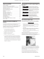
La page charge ...
La page charge ...
La page charge ...
La page charge ...
La page charge ...
La page charge ...
La page charge ...
La page charge ...
La page charge ...
La page charge ...
La page charge ...
La page charge ...
La page charge ...
La page charge ...
La page charge ...
La page charge ...
-
 1
1
-
 2
2
-
 3
3
-
 4
4
-
 5
5
-
 6
6
-
 7
7
-
 8
8
-
 9
9
-
 10
10
-
 11
11
-
 12
12
-
 13
13
-
 14
14
-
 15
15
-
 16
16
-
 17
17
-
 18
18
-
 19
19
-
 20
20
-
 21
21
-
 22
22
-
 23
23
-
 24
24
-
 25
25
-
 26
26
-
 27
27
-
 28
28
-
 29
29
-
 30
30
-
 31
31
-
 32
32
-
 33
33
-
 34
34
-
 35
35
-
 36
36


Ingersoll Rand 80445703 Stationary Reciprocating Air Compressors Manuel utilisateur
- Catégorie
- Compresseurs d'air
- Taper
- Manuel utilisateur
- Ce manuel convient également à