

MCI_Manual_V13.doc Page: 2 of 20 03555-120
Table of Contents / Inhaltsverzeichnis / Sommaire
En
1 General Notes for the User 3
2 Characteristics of the MCI Family 3
3 Installation 3
4 Modules 5
5 Additional Help 7
6 Appendix 18
7 Declaration of Conformity 20
De
1 Allgemeine Hinweise 8
2 Merkmale der MCI Familie 8
3 Installation 8
4 Module 10
5 Zusätzliche Hilfe 12
6 Anhang 18
7 Konformitätserklärung 20
Fr
1 Notes à l’utilisateur 13
2 Caractéristiques de la gamme MCI 13
3 Installation 13
4 Modules 15
5 Aide 17
6 Annexe 18
7 Certificat de conformité 20

MCI_Manual_V13.doc Page: 3 of 20 03555-120
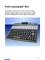
Preh Commander® MCI Family
Instruction
1 General Notes for the User
Congratulations on your purchase of the Preh Commander® MCI keyboard!
All Preh products undergo a continuous improvement process. For this reason, technical
modifications may be made without notice.
We would like to point out that improper handling, storage, actions and/or modifications can lead
to malfunctions and damage during use. If you modify our products as the end user, we are in no
way responsible for any warranties or liability, unless you have obtained an express, written
release for your case of operation.
This applies especially to unprofessional repair and maintenance work.
Any claims for damages against Preh – regardless of the legal reason – are excluded if we are
not responsible for intent or gross negligence. The above limitation does not apply to claims for
damages resulting from product liability laws.
These operating instructions apply solely to Preh Commander® keyboards of the MCI family.
If you have problems operating or programming the Preh Commander®, please contact your
dealer.
You can find the current programming and driver software, as well as further information, on
our Internet page: http://www.preh-keytec.com
2 Characteristics of the MCI Family
The Preh Commander® MCI family is characterized especially by its ergonomic and compact
design.
Depending on the housing model, the keyboards of the MCI family are equipped with the following
modules:
• glidepad or microjoystick,
• magnetic stripe reader (MSR),
• key-operated switch (KL),
• smart card read/write device (SCR).
Depending on the keypad model, keyboards of the Preh Commander® MCI family have up to 128
freely programmable key positions. In the alphanumeric keypad design, the keys of the alphabetic
section are preassigned according to the functions of a standard MF2 keyboard.
Programming of the individual key positions and any integrated modules occurs with the guidance
of menus using easy-to-use programming software. You can find the appropriate software, as well
as additional notes regarding programming, on the Internet under http://www.preh-keytec.com.
The figures in these operating instructions show the maximum configuration of the MCI 128.
However, the description applies to all keyboards of the MCI family.
3 Installation
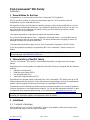
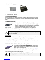
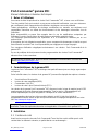
3.1 Contents of package
Before starting to use your Preh Commander®, please check whether all the parts shown below
are present and show no obvious signs of damage:

MCI_Manual_V13.doc Page: 4 of 20 03555-120
2
1 Operating Instructions and Technical Data
2 Preh Commander® MCI family keyboard
3.2 Installation of the keyboard
3.2.1 System requirements
The Preh Commander® MCI family keyboard has been developed for use with IBM-AT-compatible
PS/2 and USB systems. The keyboard can be used with all popular operating systems.
3.2.2 USB cable installation
In order to provide problem-free operation of the keyboard using USB, it
must be insured that the USB interface is supported by the operating
system. This is the case for Windows 98SE and later, as well as Linux
with a kernel version of 2.4.18 or higher.
In addition, insure that USB legacy support is activated in the BIOS of
your system.
Please see the description of your motherboard for instructions regarding the BIOS settings.
The operating systems Windows 95, Windows NT and Windows 98 do not support
the USB interface, or do so only partially. Problem-free operation is not insured in
these cases.
Procedure
• If a keyboard is already connected to the computer, please remove it.
• Now insert the USB plug of the keyboard cable into an unoccupied USB socket.
• Now restart your system or switch it on. Certain drivers may be automatically installed by the
operating system. The keyboard is then ready for use.
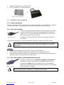
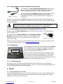
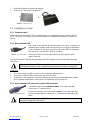
3.2.3 PS/2 cable installation (without glidepad/microjoystick)
Installation must be carried out when the computer is switched off. If
a keyboard is already connected to the computer, please remove it.
Now insert the violet 6-pin mini DIN plug (Figure 3) of the keyboard
cable into the keyboard socket provided on the computer. Insure that the
poles are correct (coding pin).
Never force the keyboard plug into the PS/2 socket on the computer. This could
result in bending of the connection pins – danger of short circuits!
Fig 3 PS/2 plug
Fig. 1 Contents of package
1
Fig. 2 USB plug

MCI_Manual_V13.doc Page: 5 of 20 03555-120
Fig. 4 PS/2 Y-cable
3.2.4 PS/2 cable installation (with glidepad/microjoystick)
Installation must be carried out when the computer is switched off.
If a keyboard and/or mouse is already connected to the computer,
please remove it.
First, insert the violet 6-pin mini DIN plug (Figure 4) of the keyboard
cable into the keyboard socket provided on the computer (violet).
Ensure that the poles are correct (coding pin).
Then insert the green 6-pin mini DIN plug (Figure 4) of the pointing device into the PS/2 mouse
socket provided on the computer (green). Ensure that the poles are correct (coding pin).
Never force the keyboard plug into the PS/2 socket on the computer. This could
result in bending of the connection pins – danger of short circuits!
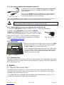
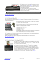
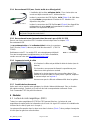
3.2.5 Cable installation for smart card read/write device (USB / RS 232)
To connect the USB model, proceed according to section 3.2.2 USB cable installation.
Installation of the serial model must be carried out when the
computer is switched off. Insert the 9-pin Sub-D connector (Figure
5) into an unoccupied serial interface on your PC (COM 1 to COM 4).
Now restart your system. The SCR module is now automatically
detected. You can find further details regarding driver installation
under http://www.preh-keytec.com.
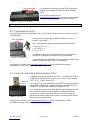
3.2.6 Cable routing When it is delivered, the connection cable is routed on the right
side (seen from above). If the cable outlet has to be moved to
the left or center, you can do this quite easily.
Lay the keyboard with the keypad facing down on a soft surface.
To move the cable outlet to the left, move the connection cable
as shown in Figure 6. Ensure that the keyboard cable is firmly
pressed into the nips provided.
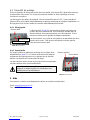
3.2.7 Functional check
After you have started your computer, all four LEDs light up briefly. Then, depending on the status
of the NumLock, CapsLock and ScrollLock, the associated LEDs light up. Your Preh Commander®
MCI is now ready for use.
4 Modules
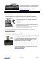
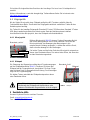
4.1 Magnetic stripe reader (MSR)
All magnetic cards according to ISO 7810 and 7811 can be read. The magnetic stripe reader
records the entire information content of the magnetic card. A LED signal (green Accept LED) is
issued after a successful read procedure.
The magnetic card can be swiped through the reading device in both directions (Figure 7). This
provides easy manipulation for both right- and left-handers.
Fig. 5 SCR serial cable
Nips
Fig. 6 cable nips

MCI_Manual_V13.doc Page: 6 of 20 03555-120
The parameters of the MSR can be set and/or modified
using the corresponding Preh programming software.
You can find further information, as well as the
associated software, in the Internet under
http://www.preh-keytec.com.
Important notice: Please hold the magnetic card near the upper edge during a swipe.
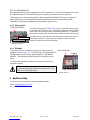
4.2 Keylock (KL)
The optional keylock (Figure 8) module has 5 positions and is supplied with 3 different keys.
All keys can be inserted and removed in both positions 0 and 1.
The following switch positions can be set with the three keys:
• SUP key: 0 1 2 3 4
• REG key: 0 1
• X key: 0 1 2
By default, the code for the new switch position is transferred to
the computer when the key is turned.
The parameters of the keylock can be set and/or modified using
the corresponding Preh programming software.
You can find further information, as well as the associated software, in the Internet under
http://www.preh-keytec.com.
4.3 Smartcard read/write device (SCR)
The EMC 3.1.1- and ISO 7816-certified SCR module of the MCI family
allows you to read and write chip cards of types T=0, T=1, I²C, 2-wire,
3-wire and PTS.
PC/SC drivers for the popular Windows operating systems (as of
Windows 98) are available as the software interface. A CT-API
interface can be placed on the PC/SC interface.
In order to read or write a chip card, carefully insert the chip card into
the read slot; make sure that the chip contact surfaces face in the
direction of the keypad (Figure 9). A slight click indicates that the end
position has been attained. Reading or writing can now be carried out.
You can find further information, as well as the associated driver
software, in the Internet under
http://www.preh-keytec.com.
Fig. 7 Magnetic stripe reader
Swipe direction
Turning direction
Fig. 8 Keylock
Fig. 9 SCR module
Contact-
surfaces

MCI_Manual_V13.doc Page: 7 of 20 03555-120
4.4 Pointing devices
With the optional microjoystick/glidepad, your MCI keyboard also has the functionality of a mouse.
No additional driver for the operating system is required to operate the pointing devices.
The drivers for the corresponding pointing device (standard 2-button PS/2 mouse / standard 2-
button USB mouse) are installed automatically after the first start of the operating system.
Thereafter, the microjoystick/glidepad is immediately ready for use.
4.4.1 Microjoystick Using the microjoystick (Figure 10), you can control the mouse arrow
in the way that a mouse is used. Pressing the side of the microjoystick
moves the mouse arrow in the corresponding direction. The stronger
the pressure on the side, the faster the movement of the mouse arrow.
The two buttons to the left of the microjoystick correspond to those of
a two-button mouse. The lower one is assigned to the left mouse
button, the upper one to the right button.
4.4.2 Glidepad
The mouse arrow is controlled by moving your fingers on the
glidepad surface (Figure 11). To do this, touch the glidepad with a
fingertip and move your finger, pressing lightly, in the desired
direction. The mouse arrow then follows the movement of your
finger.
The two buttons below the glidepad correspond to those of a
two-button mouse.
The glidepad is a capacitive system. It is not possible
to operate the glidepad while wearing gloves or using
other non-conducting objects.
5 Additional Help
You can reach our Keyboard Service department under:
Email: [email protected]
Fax: +49 9771 / 92-152
Fig. 10 Microjoystick
Left mouse button
Right mouse button
Microjoystick
Fig. 11 Glidepad
Glide
p
ad
Left mouse button
Ri
g
ht mouse button

MCI_Manual_V13.doc Page: 8 of 20 03555-120
Preh Commander® MCI Familie
Kurzanleitung
1 Allgemeine Anwenderhinweise
Wir gratulieren Ihnen zum Kauf der Preh Commander® MCI Tastatur.
Sämtliche Preh-Produkte unterliegen einem kontinuierlichen Verbesserungsprozeß. Aus diesem
Grund behalten wir uns technische Änderungen vor.
Wir weisen darauf hin, daß unsachgemäße Behandlung, Lagerung, Einflußnahme und/oder
Modifikation zu Störungen und Schäden im Einsatz führen kann.
Sofern Sie unsere Produkte anwenderseitig verändern, übernehmen wir keinerlei Gewährleistung
oder Haftung, es sei denn, es liegt Ihnen von uns eine ausdrückliche, schriftliche Freigabe für
Ihren Einsatzfall vor.
Dies gilt insbesondere auch für unfachmännische Reparatur- und Wartungsarbeiten.
Etwaige Schadensersatzansprüche gegen die Preh GmbH - gleich aus welchem Rechtsgrund -
sind ausgeschlossen, soweit uns nicht Vorsatz oder grobe Fahrlässigkeit trifft. Obige
Beschränkung gilt nicht für Schadensersatzansprüche aus dem Produkthaftungsgesetz.
Die vorliegende Bedienungsanleitung gilt ausschließlich für die Preh Commander® Tastaturen der
MCI Familie.
Falls Sie Probleme im Umgang bzw. mit der Programmierung des Preh Commander® haben
sollten, so wenden Sie sich bitte an Ihren zuständigen Händler.
Die jeweils aktuelle Programmier- und Treibersoftware, sowie weitere Informationen finden Sie
auf unserer Internet-Seite http://www.preh-keytec.de
2 Merkmale der MCI Familie
Die Preh Commander® MCI Familie zeichnet sich besonders durch ihr ergonomisches und
kompaktes Design aus.
Je nach Gehäuseausführung können die Tastaturen der MCI Familie mit den folgenden Modulen
ausgestattet werden:
• Glidepad oder Microjoystick,
• Magnetkartenleser (MSR),
• Schlüsselschalter (KL),
• Smart Card Lese-/Schreibgerät (SCR).
Die Tastaturen der Preh Commander® MCI Familie verfügen, je nach Ausführung des
Tastenfeldes, über bis zu 128 frei programmierbare Tastenpositionen. In der alphanumerischen
Ausführung des Tastenfeldes werden werksseitig die Tasten des Alpha-Bereiches mit einer
Vorbelegung versehen, die der Funktion einer Standard-MF2-Tastatur entsprechen.
Die Programmierung der einzelnen Tastenpositionen und der evtl. integrierten Module erfolgt
menügeführt über eine einfach zu bedienende Programmiersoftware. Die entsprechende
Software, sowie weitere Hinweise zur Programmierung, finden Sie im Internet unter
http://www.preh-keytec.de.
Die Bilder dieser Bedienungsanleitung stellen die Maximalkonfiguration der MCI 128 dar. Die
Beschreibung ist inhaltlich jedoch für alle Tastaturen der MCI Familie gültig.
3 Installation
3.1 Verpackungsinhalt
Bitte überprüfen Sie vor der Inbetriebnahme Ihres Preh Commander®, ob alle nachfolgend
aufgeführten Teile vorhanden und optisch unbeschädigt sind:

MCI_Manual_V13.doc Page: 9 of 20 03555-120
2
1 Diese Kurzanleitung
2 Preh Commander® MCI Tastatur
3.2 Installation der Tastatur
3.2.1 Systemvoraussetzungen
Die Preh Commander® MCI Familie wurde für den Einsatz an IBM-AT kompatiblen PS/2- bzw.
USB-Systemen entwickelt. Die Tastatur kann unter allen gängigen Betriebssystemen betrieben
werden.
3.2.2 Kabelinstallation USB
Um einen fehlerfreien Betrieb der Tastatur unter USB zu
gewährleisten, muß sichergestellt sein, daß die USB-Schnittstelle
vom Betriebssystem unterstützt wird. Dies ist ab Windows 98SE
aufwärts, sowie unter Linux mit Kernelversionen ab 2.4.18 möglich.
Stellen Sie zudem auf Ihrem System sicher, daß die USB-
Unterstützung (USB Legacy Support) im BIOS aktiviert ist.
Die Anweisungen zu den BIOS-Einstellungen entnehmen Sie bitte der Beschreibung Ihres
Motherboards.
Die Windows Betriebssysteme Windows 95, Windows NT und Windows 98
unterstützen die USB Schnittstelle nicht oder nur teilweise. Ein fehlerfreier Betrieb ist
hier nicht gewährleistet.
Vorgehensweise
• Sofern Sie bereits eine Tastatur am Rechner angeschlossen haben, stecken Sie diese bitte
aus.
• Stecken Sie nun den USB-Stecker des Tastaturkabels in eine freie USB-Buchse.
• Starten Sie nun ihr System neu bzw. schalten Sie es ein. Gegebenenfalls werden vom
Betriebssystem noch einige Treiber automatisch installiert. Die Tastatur ist anschließend
einsatzbereit.
3.2.3 Kabelinstallation PS/2 (ohne Glidepad bzw. Microjoystick)
Die Installation muß bei ausgeschaltetem Rechner vorgenommen
werden. Sofern Sie bereits eine Tastatur am Rechner angeschlossen
haben, stecken Sie diese bitte aus.
Stecken Sie nun den violetten 6-poligen Mini-DIN-Stecker (Bild 3) des
Tastaturkabels in die dafür vorgesehene rechnerseitige Tastaturbuchse.
Achten Sie dabei auf die richtige Polung (Codierstift).
Den Tastaturstecker niemals mit Gewalt in die PS/2-Buchse am Computer
einstecken. Dadurch können die Anschlußpins verbogen werden –
Kurzschlußgefahr!
Bild 2 USB-Stecker
Bild 3 PS/2-Stecker
Bild 1 Verpackungsinhalt
1

MCI_Manual_V13.doc Page: 10 of 20 03555-120
Bild 4 PS/2 Y-Kabel
Klemmstellen
Bild 6 Kabelklemmstellen
3.2.4 Kabelinstallation PS/2 (mit Glidepad bzw. Microjoystick)
Die Installation muß bei ausgeschaltetem Rechner vorgenommen
werden. Sofern Sie bereits eine Tastatur und/oder eine Maus am
Rechner angeschlossen haben, stecken Sie diese bitte aus.
Stecken Sie zuerst den violetten 6-poligen Mini-DIN-Stecker (Bild 4)
des Tastaturkabels in die dafür vorgesehene rechnerseitige
Tastaturbuchse (violett). Achten Sie dabei auf die richtige Polung
(Codierstift).
Stecken Sie anschließend den grünen 6-poligen Mini-DIN-Stecker (Bild 4) des Zeigergerätes in
die dafür vorgesehene rechnerseitige PS/2-Mausbuchse (grün). Achten Sie dabei auf die richtige
Polung (Codierstift).
Den Stecker niemals mit Gewalt in die PS/2-Buchse am Computer einstecken.
Dadurch können die Anschlußpins verbogen werden – Kurzschlußgefahr!
3.2.5 Kabelinstallation Smartcard Lese-/Schreibgerät (USB bzw. RS 232)
Beim Anschluß der USB-Ausführung gehen Sie bitte wie unter Kapitel 3.2.2 Kabelinstallation
USB beschrieben vor.
Die Installation der serielle Ausführung muß bei ausgeschaltetem
Rechner vorgenommen werden. Stecken Sie den 9-poligen Sub-D-
Steckverbinder (Bild 5) in eine freie serielle Schnittstelle ihres PCs
(COM 1 bis COM4).
Starten Sie nun ihr System neu. Das SCR-Modul wird nun automatisch erkannt. Weitere Details
zur Treiberinstallation finden Sie unter http://www.preh-keytec.de.
3.2.6 Kabelführung Im Auslieferungszustand ist das Anschlußkabel auf der rechten
Seite ausgeführt (von oben betrachtet). Sollte es erforderlich
sein, den Kabelauslaß nach links oder mittig zu verlegen, so
können Sie dies auf einfache Weise tun.
Legen Sie hierfür die Tastatur mit dem Tastenfeld nach unten
auf eine weiche Unterlage. Zur Modifikation auf Kabelauslaß
"links" verlegen Sie nun das Anschlußkabel so, wie in Bild 6
dargestellt. Achten Sie darauf, daß die Tastaturleitung fest in die
vorgesehenen Klemmstellen gedrückt wird.
3.2.7 Funktionskontrolle
Nachdem Sie Ihren Computer eingeschaltet haben, leuchten alle vier LED‘s kurzzeitig auf.
Anschließend leuchten je nach Status von Num-, Caps-, und ScrollLock die dazugehörigen LED's.
Ihr Preh Commander® MCI ist nun betriebsbereit.
4 Module
4.1 Magnetkartenleser (MSR)
Es können alle Magnetkarten nach ISO 7810 und 7811 gelesen werden. Der Magnetkartenleser
erfaßt den gesamten Informationsgehalt der Magnetkarte. Nach einem gültigen Lesevorgang
erfolgt ein LED-Signal (Accept-LED grün).
Bild 5 SCR-Kabel seriell

MCI_Manual_V13.doc Page: 11 of 20 03555-120
Die Magnetkarte kann in beiden Richtungen durch das
Lesegerät gezogen werden (Bild 7). Hierdurch ist eine
einfache Handhabung sowohl für Rechts- als auch für
Linkshänder gewährleistet.
Die Parameter des MSR-Lesers können durch
entsprechende Preh Programmiersoftware eingestellt
und/oder verändert werden.
Wichtiger Hinweis: Beim Durchzug ist die Karte nur im oberen Randbereich zu greifen.
Weitere Informationen, sowie die dazugehörige Software finden Sie im Internet unter
http://www.preh-keytec.de.
4.2 Schlüsselschalter (KL)
Das Optionsmodul Schlüsselschalter (Bild 8) besitzt 5 Stellungen und wird mit 3 verschiedenen
Schlüsseln ausgeliefert.
Alle Schlüssel können sowohl in Position „0“ als auch in Position
„1“ gezogen und gesteckt werden.
Mit den drei verschiedenen Schlüsseln lassen sich jeweils die
folgenden Schalterstellungen einstellen:
• Schlüssel „SUP“: 0 1 2 3 4
• Schlüssel „REG“: 0 1
• Schlüssel „X“: 0 1 2
Standardmäßig wird bei Drehung des Schlüssels der Code für die
neue Schalterstellung an den Computer übertragen.
Die Parameter des Schlüsselschalters können durch entsprechende Preh Programmiersoftware
eingestellt und/oder verändert werden.
Weitere Informationen, sowie die dazugehörige Software finden Sie im Internet unter
http://www.preh-keytec.de.
4.3 Smartcard Lese- Schreibgerät (SCR)
Das EMV 3.1.1 und ISO 7816 zertifizierte SCR-Modul der MCI Familie
ermöglicht Ihnen, Chipkarten vom Typ T=0, T=1, I²C, 2-wire 3-wire und
PTS zu lesen und zu beschreiben.
Als Software-Schnittstelle stehen PC/SC Treiber für die gängigen
Windows Betriebssysteme (ab Windows 98) zur Verfügung. Eine CT-
API Schnittstelle kann auf die PC/SC Schnittstelle aufgesetzt werden.
Um eine Chipkarte lesen oder beschreiben zu können, führen Sie die
Chipkarte vorsichtig in den Leseschlitz ein, wobei die Chip-
Kontaktflächen in Richtung des Tastenfeldes zeigen (Bild 9).
Drehrichtung
Bild 8 Schlüsselschalter
Bild 9 SCR-Modul
Kontakt-
flächen
Bild 7 Magnetkartenleser
Durchzugsrichtung

MCI_Manual_V13.doc Page: 12 of 20 03555-120
Ein leichter Klick signalisiert das Erreichen des Anschlags. Die Lese- bzw. Schreibposition ist
erreicht.
Weitere Informationen, sowie die dazugehörige Treibersoftware finden Sie im Internet unter
http://www.preh-keytec.de.
4.4 Zeigergeräte
Mit der Option Microjoystick bzw. Glidepad verfügt Ihre MCI Tastatur zusätzlich über die
Funktionalität einer Maus. Zum Betrieb der Zeigergeräte wird kein zusätzlicher Treiber für das
Betriebssystem benötigt.
Die Treiber für das jeweilige Zeigergerät (Standard 2-Tasten PS/2-Maus bzw. Standard 2-Tasten
USB-Maus) werden automatisch nach dem ersten Start des Betriebssystems installiert.
Anschließend ist der Microjoystick, bzw. das Glidepad sofort betriebsbereit.
4.4.1 Microjoystick Mit dem Microjoystick (Bild 10) steuern Sie den Mauszeiger ähnlich
wie mit der Maus gewohnt. Durch einen seitlichen Druck auf den
Microjoystick wird eine Bewegung des Mauszeigers in die
entsprechende Richtung umgesetzt. Je stärker der seitliche Druck,
desto schneller bewegt sich der Mauszeiger.
Die beiden Tasten auf der linken Seite des Microjoystick entsprechen
denen einer Zweitasten-Maus. Die untere ist der linken, die obere der
rechten Maustaste zugeordnet.
4.4.2 Glidepad
Die Steuerung des Mauszeigers erfolgt durch Fingerbewegungen
auf der Glidepadoberfläche (Bild 11). Berühren Sie hierzu das
Glidepad mit der Fingerspitze und „verschieben“ Sie Ihren Finger
unter leichtem Druck in die gewünschte Richtung. Der Mauszeiger
folgt nun der Fingerbewegung.
Die beiden Tasten unterhalb des Glidepad entsprechen denen
einer Zweitasten-Maus.
Das Glidepad ist ein kapazitives System. Eine
Bedienung des Glidepads mit Handschuhen oder
anderen nichtleitenden Gegenständen ist nicht möglich.
5 Zusätzliche Hilfe
Unseren Keyboard Service erreichen Sie unter:
Email: [email protected]
Fax: +49 9771 / 92-152
Bild 10 Microjoystick
Maustaste „links“
Maustaste „rechts“
Microjoystick
Bild 11 Glidepad
Glide
p
ad
Maustaste
„
links“
Maustaste „rechts“

MCI_Manual_V13.doc Page: 13 of 20 03555-120
Preh Commander® gamme MCI
Manuel d’utilisation et données techniques
1 Notes à l’utilisateur
Vous venez de faire l’acquisition d’un clavier Preh Commander® MCI et nous vous en félicitons.
Tous les produits Preh sont soumis à un processus continuel d’amélioration, nous nous réservons
par conséquent le droit d’apporter des modifications techniques sans avis préalable.
Toutes manipulations, conditions de stockage, modifications ou mesures non-conformes sont
susceptibles d’entraîner un défaut de fonctionnement et des dommages irréversibles lors de
l’utilisation.
Notre responsabilité ne pourra être engagée dans le cas de modifications entreprises par
l’utilisateur, à moins d’avoir obtenu de notre part une autorisation préalable écrite.
Ceci s'applique particulièrement aux réparations et à la maintenance réalisées par un non
professionnel.
A l’exception des lois obligatoires applicables, aucun versement de dommages et interêts ne peut
être réclamé à la société Preh si sa responsabilité pour négligence n’est pas engagée.
Ces consignes d'utilisation s’appliquent exclusivement aux claviers Preh Commander® de la
gamme MCI.
En cas de problème de fonctionnement ou de programmation des claviers Preh Commander®
adressez-vous à votre revendeur.
Les logiciels de programmation, drivers et autres informations sont disponibles sur notre site
Internet http://www.preh-keytec.com
2 Caractéristiques de la gamme MCI
La gamme Preh Commander® MCI se distingue tout particulièrement par son design ergonomique
et compact.
Selon le boîtier retenu, les claviers de la gamme MCI peuvent être équipés des options suivantes :
• Souris tactile ou Microjoystick,
• Lecteur de carte magnétique (MSR),
• Commutateur à clé (KL),
• Lecteur de carte à puce (lecture/écriture) (SCR).
Les claviers de la gamme Preh Commander® MCI disposent- selon le type de matrice-jusqu’à 128
emplacements de touches librement programmables. Pour la version alphanumérique les
touches alphabétiques sont pré-assignées à l’identique d’un clavier standard MF2.
La programmation des touches et des modules intégrés se fait à l’aide d’un logiciel de
programmation facile à utiliser et que vous pourrez trouver accompagné d’explications sur notre
site http://www.preh-keytec.com.
Les photos présentées dans ce manuel d’utilisation sont celles du MCI128 en configuration
maximale. Toutes les explications données sont applicables à l’ensemble de la gamme MCI
3 Installation
3.1 Contenu du colis
Avant la mise en marche de votre Preh Commander® merci de bien vouloir vérifier que le colis
contient bien les éléments suivants, en parfait état et non-endommagés :

MCI_Manual_V13.doc Page: 14 of 20 03555-120
2
1 Manuel d’utilisation et données techniques
2 Clavier Preh Commander® gamme MCI
3.2 Installation du clavier
3.2.1 Systèmes requis
La gamme Preh Commander® MCI a été developpée en compatibilité avec les sytèmes IBM-AT
PS/2 - et/ou USB. Les claviers fonctionnent sous tous les systèmes d’exploitation courants du
marché.
3.2.2 Raccordement USB
Pour éviter tout problème de fonctionnement du clavier, s’assurer au
préalable que l’interface USB est reconnue par le logiciel d’exploitation.
C’est notamment le cas pour les versions Windows 98SE et suivantes,
ainsi que pour Linux version 2.4.18 ou suivantes.
Vérifier que l’USB est activé dans le BIOS de votre système (USB
Legacy Support).
Pour les informations relatives aux paramètres du BIOS reportez-vous aux instructions de votre
carte mère.
Windows 95, Windows NT et Windows 98 ne reconnaissent pas ou seulement
partiellement l’interface USB. Un parfait fonctionnement ne peut donc être garanti.
Processus
• Si un autre clavier est déjà connecté à votre ordinateur, débranchez-le.
• Connectez le câble USB du clavier dans une prise USB libre.
• Redémarrez votre ordinateur. Certains programmes peuvent être automatiquement installés
par le système d’exploitation. Votre clavier est maintenant prêt à fonctionner.
3.2.3 Raccordement PS/2 (sans souris tactile ni Microjoystick)
L’installation doit se faire ordinateur éteint. Si un clavier est déjà
connecté au PC, débranchez-le.
Insérez le connecteur mini DIN 6 poles violet (Photo 3) du câble dans
la prise correspondante à l’arrière du PC. Attention à la disposition des
pôles.
Ne jamais forcer un connecteur PS2 lors du branchement. Vous risqueriez de tordre
les picots. Danger de court circuit !
Photo 3 Connecteur PS/2
Photo 1 Contenu du colis
1
Photo 2 Connecteur USB

MCI_Manual_V13.doc Page: 15 of 20 03555-120
Photo 4 PS/2 Câble Y
Guides de
câble
Photo 6 guide de câble
3.2.4 Raccordement PS/2 (avec Souris tactile et ou Microjoystick)
L’installation doit se faire ordinateur éteint. Si un clavier et/ou une
souris sont déjà connectés au PC, débranchez-les.
Insérez le connecteur mini DIN 6 pôles violet (Photo 4) du câble dans
la prise violette correspondante à l’arrière du PC. Attention à la
disposition des pôles.
Insérez le connecteur mini DIN 6 pôles vert (Photo 4) du dispositif de
pointage dans la prise (verte) correspondante à l’arrière du PC.
Attention à la disposition des pôles.
Ne jamais forcer un connecteur PS2 lors du branchement. Vous risqueriez de tordre
les picots. Danger de court circuit !
3.2.5 Raccordement lecteur (lecture/écriture) de carte à puce (USB / RS 232)
Dans le cas d’une connection USB. Procédez comme indiqué dans le chapitre 3.2.2
Raccordement USB.
Le raccordement série se fait ordinateur éteint. Insérez le connecteur
Sub-D 9 voies (Photo 5) dans un port série libre de votre PC (COM 1 à
COM4).
Redémarrez votre PC. Le module SCR est automatiquement détecté.
Pour tout renseignement complémentaires sur le Driver d’installation,
rendez vous sur notre site http://www.preh-keytec.com.
3.2.6 Logement et sortie de câble
A la livraison le câble sort par défaut à droite du clavier (vue de
dessus).
Si nécessaire, vous pouvez facilement le repositionner pour
obtenir une sortie gauche ou centrale.
Retournez le clavier et posez le sur une surface plane. Pour
modifier la sortie dû câble et le faire passer à gauche, déplacez
le comme indiqué sur la photo 6.
Assurez-vous que le câble est solidement fixé dans les guides.
3.2.7 Contrôle de fonctionnement
Après avoir mis en marche votre ordinateur, les 4 leds s’allument brièvement. Puis, en fonction
des statuts numlock, Capslock et ScrollLock les leds correspondantes s’allument. Votre
Preh Commander® MCI est prêt à fonctionner.
4 Modules
4.1 Lecteur de carte magnétique (MSR)
Toutes les cartes magnétiques ISO 7810 et 7811 peuvent être lues. Le lecteur de carte
magnétique récupère toutes les informations de la carte. Un signal LED est émis à la validation de
la lecture de la carte (Voyant vert « Accept »).
La carte peut être passée dans les deux sens dans le lecteur, (Photo 7) donc pratique à manipuler
à la fois pour les gauchers et les droitiers.
Photo 5 Câble SCR série

MCI_Manual_V13.doc Page: 16 of 20 03555-120
Les paramètres du lecteur de carte MSR peuvent être
installés et/ou modifiés à l’aide du logiciel spécifique
PREH.
Vous pouvez consulter le site
http://www.preh-keytec.com pour obtenir de plus amples
informations ainsi que les logiciels correspondants.
Remarque importante: Veiller à tenir la carte par le haut lors de son passage dans le lecteur.
4.2 Commutateur à clé (KL)
Le module optionnel du commutateur à clé (Photo 8) offre 5 positions et est livré avec un jeu de 3
clés différentes.
Toutes les clés peuvent être insérées et retirées à la fois en
position 0 et position 1.
Les 3 clés autorisent respectivement les positions suivantes :
• Clé „SUP“: 0 1 2 3 4
• Clé „REG“: 0 1
• Clé „X“: 0 1 2
Par défaut, le code de la nouvelle position du commutateur est
transféré à l'ordinateur au moment où la clef est tournée.
Les paramètres du commutateur à clé peuvent être installés et/ou
modifiés à l’aide du logiciel PREH correspondant.
Vous pouvez consulter le site http://www.preh-keytec.com pour obtenir de plus amples
informations ainsi que les logiciels correspondants.
4.3 Lecteur de carte à puce (lecture/écriture) (SCR)
Le module de lecteur de carte à puce EMV 3.1.1 certifié ISO 7816 de
la gamme MCI permet de lire et écrire sur les cartes à puce de type
T=0, T=1, I²C, 2-wire 3-wire et PTS.
Les drivers PC/SC sont disponibles en logiciel d’interfaçage pour tous
les systèmes d’exploitation courants (à partir de Windows 98). Une
interface CT-API peut être installée sur l’interface PC/SC.
Pour lire/écrire sur une carte à puce, introduire délicate-ment la carte
dans la fente du lecteur, en prenant garde à diriger la surface de
contact de la carte en direction du clavier (Photo 9).Un léger clic
signale le bon enclenchement de la carte. Le lecteur est alors prêt à
fonctionner en lecture/écriture.
Vous pouvez consulter le site http://www.preh-keytec.com pour obtenir de plus amples
informations ainsi que les logiciels correspondants.
Photo 7 lecteur de carte magnétique
Sens de passage
Sens de rotation
Photo 8 Commutateur à clé
Photo 9 Module SCR
Surface de
contact

MCI_Manual_V13.doc Page: 17 of 20 03555-120
4.4 Dispositifs de pointage
Grâce aux options de Microjoystick et/ou de souris tactile, votre clavier MCI dispose de toutes les
fonctionnalités d’une souris. Il n’est pas nécessaire d’installer un driver spécifique pour faire
fonctionner ces options.
Les drivers pour les options de pointage (Souris standard 2 boutons PS/2 - Souris standard 2
boutons USB) sont installés automatiquement au premier démarrage du système d’exploitation. Le
Microjoystick et/ou la souris tactile sont ensuite immédiatement fonctionnels.
4.4.1 Microjoystick Le Microjoystick (Photo 10) vous permet de diriger le pointeur tout
comme une souris traditionnelle. Vous orientez le pointeur dans la
direction désirée d’une simple pression sur le Microjoystick. Plus la
pression est forte, plus le pointeur se déplace rapidement.
Les deux touches sur le côté du microjoystick correspondent aux deux
boutons de la souris. Celle du bas correspond au bouton gauche,
celle du haut au bouton droit.
4.4.2 Souris tactile
On bouge la flèche en déplaçant ses doigts sur la surface de la
tablette tactile (Photo 11). Le contact se fait du bout du doigt en
maintenant une légère pression et en glissant vers la direction
désirée. Le pointeur suit le mouvement du doigt.
Les deux boutons situés au bas de la souris tactile correspondent
aux deux boutons de la souris traditionnelle.
La souris tactile est un système capacitif. L’utilisation
de gants ou autres moyens non-conducteurs n’en
permet pas son fonctionnement.
5 Aide
Vous pouvez contacter notre département claviers au (anglais ou allemande):
Email: [email protected]
Fax: +49 9771 / 92-152
Photo 10 Microjoystick
Bouton „
g
auche“
Bouton „droit“
Microjoystick
Photo 11 Souris tactile
Souris tactile
Bouton
„g
auche“
Bouton „Droit“

MCI_Manual_V13.doc Page: 18 of 20 03555-120
6 Appendix / Anhang / Annexe
6.1 Technical data / Technische Daten / Données techniques
6.1.1 Electronics / Elektronik / Electronique
Power supply: 5VDC ±5%
Power consumption: max. 60 mA (without optional modules)
Keyboard LEDs: ACCEPT, NUM LOCK, CAPS LOCK, SCROLL LOCK
Interface: USB 1.1 or IBM PC-AT, PS/2 and compatible systems
6.1.2 ESD and EMC behavior / ESD- und EMV-Verhalten / Conformité ESD- EMV
CE symbol
Unwanted emission EN55022, class B
FCC subpart 15 class A
Immunity to interference immunity against high-frequency electromagnetic fields; penetration
test value = 3 V/m
immunity against electrostatic discharge according to EN 50082-1;
penetration test value = 8 kV
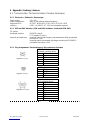
6.1.3 Plug assignement / Steckerbelegung / Raccordement électrique
PS/2 Mini-DIN 6pol. (male)
keyboard / pointing device
1 Data
2 -
3 GND
4 +5V
5 Clock
6 -
USB Plug A
1 VCC
2 -DATA
3 +DATA
4 GND
Sub-D 9pol. (female)
SCR read/write device
1 -
2 TxD
3 RxD
4 DTR
5 GND
6 DSR
7 RTS
8 CTS
9 NC
Seitenumbruch
Fig. 12.1 PS/2 plug
Fig. 12.2 USB plug
Fig. 12.3 RS 232 plug

MCI_Manual_V13.doc Page: 19 of 20 03555-120
6.1.4 Climatic parameters / Klimatische Parameter / Environnement
Temperature ranges
Storage/transport -40°C to +60°C
Operation ± 0°C to +50°C
Relative humidity 5% to 93%
Air pressure 700hPa to 1060 hPa
Climatic test category 0/050/21 according to DIN-IEC 68, part 1, appendix A
6.1.5 Mechanical system / Mechanik / Mécanique
Keys
Actuating force 0.6 N
Stroke strength 10N, 1 min.
Lifetime >3 x 10⁷ operations per contact element (typical value)
Keystroke 3.5 mm
Grid spacing 19 mm
6.1.6 Protection class / Schutzart / Indice de protection
IP 54 according to DIN 40050/IEC 529
valid only for the keypad in the direction of actuation
6.1.7 Material and surfaces / Werkstoffe und Oberflächen / Matières et surfaces
Housing ABS
Guide frame polystyrene
Film-inegrat. circuit polyester film
Sealing membrane Trevira
Key caps PBT/POM
Contact mat silicone rubber

MCI_Manual_V13.doc Page: 20 of 20 03555-120
7 Declaration of Conformity / Konformitätserklärung / Certificat de
conformité
This is to certify that all varieties of statements of compliance exist for the Preh Commander® MCI
family.
Of course, you can request us to send you these if you provide the precise type designation (see
the type label on the bottom of the device).
Preh KeyTec GmbH
An der Stadthalle
D-97616 Bad Neustadt an der Saale, Germany
Fax: +49-9771-92-105
FCC Warning Statement
NOTE: This equipment has been tested and found to comply with the limits for a Class A digital
device, pursuant to Part 15 of the FCC Rules. These limits are designed to provide reasonable
protection against harmful interference when the equipment is operated in a commercial
environment. This equipment generates, uses and can radiate radio frequency energy, and, if not
installed and used in accordance with the instruction manual, may cause harmful interference to
radio communications. Operation of this equipment in a residential area is likely to cause harmful
interference in which case the user will be required to correct the interference at his own expense.
Copyright
© Copyright Preh KeyTec GmbH 2005
Published by Preh KeyTec GmbH.
Preh KeyTec GmbH reserves the right to update/modify the products described in this manual, as well as the manual itself, at any
time without prior notice.
These operating instructions may not be copied, edited, transformed into electronic form or translated into other languages without
prior written consent by Preh KeyTec GmbH.
Trademarks
The brand and product names mentioned in these operating instructions are trademarks / registered trademarks of the
corresponding owner.
Examples:
Microsoft, Windows, Windows 95, Windows 98, Windows NT, Windows 2000, Windows XP are registered trademarks of Microsoft
Corporation
-
 1
1
-
 2
2
-
 3
3
-
 4
4
-
 5
5
-
 6
6
-
 7
7
-
 8
8
-
 9
9
-
 10
10
-
 11
11
-
 12
12
-
 13
13
-
 14
14
-
 15
15
-
 16
16
-
 17
17
-
 18
18
-
 19
19
-
 20
20


Keytec Preh Commander MCI Series Manuel utilisateur
- Taper
- Manuel utilisateur
dans d''autres langues
Autres documents
-
PrehKeyTec MCI 30 Mode d'emploi
-
Eiki LC-NB2 Manuel utilisateur
-
Korg EC-510 Manuel utilisateur
-
Sanyo POAMD07MCI - Digital AV Player Install And Operation Instructions
-
OK. OMW 230 Manuel utilisateur
-
Metrix 462 C Le manuel du propriétaire
-
Clatronic mwg 746 h Manuel utilisateur
-
Clatronic MWG 788 Manuel utilisateur