Wiring Instructions IS-18-LED Instrucciones de cableado IS-18-LED Instructions de câblage IS-18-LED
IMPORTANT: DO NOT ATTACH THE BLACK
OR RED WIRES FROM THE FIXTURE STEMS
OR DRIVER TO THE SUPPLY WIRES COMING
FROM THE JUNCTION BOX. IT WILL DAMAGE
THE LEDS AND DRIVER.
FIXTURE WILL HAVE TO BE REPLACED AT CUSTOMERS EXPENSE.
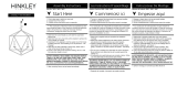
STEP 1 connect the red wire (1) exiting the fixture stem (S),
to the red wire on the driver (2) located in the canopy - see
DRAWING 1.
STEP 2 next to the red wire on the driver, there is a black
wire (3). Connect this wire to the black wire (4) exiting from
the fixture stem (S).
STEP 3 on the driver there is a black (5) and white (6) wire
next to each other. Connect the white wire (6) from the
driver to the white wire (7) coming from the junction box (J).
STEP 4 connect the black wire (8) from the junction box (J)
to the first switch wire (10)
STEP 5 connect the black wire from the driver (5) to the
second switch wire (9)
STEP 6 connect driver ground wire (11) and fixture ground
wire (12) to mounting plate, using the green ground screw,
or to the ground wire exiting the junction box.
J
black
negro
noir
white
blanco
blanc
black
negro
noir
red
roja
rouge
red
roja
rouge
black
negro
noir
red
roja
rouge
black
negro
noir
white
blanco
blanc
fixture stem
tallo para colgar
tige pour accrocher
1
3
2
4
56
7
8
DRIVER
S
IMPORTANTE: NO COLOQUE LOS
CABLES NEGROS O ROJOS DE LOS TIROS
DE LA FIJACIÓN O EL CONDUCTOR A LOS
CABLES DE SUMINISTRO QUE VIENEN DE
LA CAJA DE JUNTOS. DAÑARÁ A LOS
LEDS Y AL DRIVER.
LUMINARIA TENDRÁ QUE SER REEMPLAZADA EN GASTOS
DE LOS CLIENTES.
PASO 1 conecte el cable rojo (1) que sale del vástago
del accesorio (S), al cable rojo en el impulsor (2)
ubicado en el dosel - vea el DIBUJO 1.
PASO 2 al lado del cable rojo en el controlador, hay un
cable negro (3). Conecte este cable al cable negro (4)
que sale del vástago del accesorio (S).
PASO 3 en el controlador hay un cable negro (5) y
blanco (6) uno al lado del otro. Conecte el cable blanco
(6) del controlador al cable blanco (7) que viene de la
caja de conexiones (J).
PASO 4 conecte el cable negro (8) de la caja de
conexiones (J) al primer cable del interruptor (10)
PASO 5 conecte el cable negro del controlador (5) al
segundo cable del interruptor (9)
PASO 6 conecte el cable de tierra del controlador (11)
y el cable de tierra del dispositivo (12) a la placa de
montaje, usando el tornillo de tierra verde, o al cable de
tierra que sale de la caja de conexiones
IMPORTANT: NE FIXEZ PAS LES FILS
NOIRS OU ROUGES DES TIGES D’APPAREIL
OU DU PILOTE AUX FILS D’ALIMENTATION
EN PROVENANCE DE LA BOÎTE DE
JONCTION. IL ENDOMMAGERA LES LEDS
ET LE DRIVER.
LUMINAIRE DOIT ÊTRE REMPLACÉ AUX FRAIS DES CLIENTS.
ÉTAPE 1 connectez le fil rouge (1) sortant de la tige du
luminaire (S), au fil rouge sur le pilote (2) situé dans la
verrière - voir DESSIN 1.
ÉTAPE 2 à côté du fil rouge sur le driver, il y a un fil noir
(3). Connectez ce fil au fil noir (4) sortant de la tige du
luminaire (S).
ÉTAPE 3 sur le pilote, il y a un fil noir (5) et blanc (6)
l'un à côté de l'autre. Connectez le fil blanc (6) du driver
au fil blanc (7) provenant de la boîte de jonction (J).
ÉTAPE 4 connectez le fil noir (8) de la boîte de jonction
(J) au premier fil du commutateur (10)
ÉTAPE 5 connectez le fil noir du conducteur (5) au
deuxième fil du commutateur (9)
ÉTAPE 6 connectez le fil de terre du pilote (11) et le fil
de terre du luminaire (12) à la plaque de montage, à
l'aide de la vis de terre verte, ou au fil de terre sortant
de la boîte de jonction
Ground wire
Cable de tierra
Fil de terre
HINKLEY 33000 Pin Oak Parkway, Avon Lake, OH 44012 800.446.5539 / 440.653.5500 hinkley.com
H
I
N
K
L
E
Y
SWITCH
9
10
Ground
wire
11
12