Adlink PXES-2788 Series Le manuel du propriétaire
- Catégorie
- Cartes / adaptateurs d'interface
- Taper
- Le manuel du propriétaire

PXES-2788 Series
PXI Express Chassis
User’s Manual
Manual Rev.: 1.0
Revision Date: Oct. 22, 2023
Part No: 50M-70433-1000

ii Revision History
Revision History
Revision Release Date Description of Change(s)
1.0 2023-10-22 Initial release

Preface iii
PXES-2788 Series
Preface
Copyright © 2023 ADLINK Technology, Inc.
This document contains proprietary information protected by copy-
right. All rights are reserved. No part of this manual may be repro-
duced by any mechanical, electronic, or other means in any form
without prior written permission of the manufacturer.
Disclaimer
The information in this document is subject to change without prior
notice in order to improve reliability, design, and function and does
not represent a commitment on the part of the manufacturer.
In no event will the manufacturer be liable for direct, indirect,
special, incidental, or consequential damages arising out of the
use or inability to use the product or documentation, even if
advised of the possibility of such damages.
ADLINK is committed to fulfill its social responsi-
bility to global environmental preservation
through compliance with the European Union's
Restriction of Hazardous Substances (RoHS)
directive and Waste Electrical and Electronic
Equipment (WEEE) directive. Environmental
protection is a top priority for ADLINK. We have
enforced measures to ensure that our products,
manufacturing processes, components, and raw
materials have as little impact on the environment as possible.
When products are at their end of life, our customers are encour-
aged to dispose of them in accordance with the product disposal
and/or recovery programs prescribed by their nation or company.
Battery Labels (for products with battery)
ᘄ㟁ụㄳᅇᨲ

iv Preface
California Proposition 65 Warning
WARNING: This product can expose you to chemicals
including acrylamide, arsenic, benzene, cadmium,
Tris(1,3-dichloro-2-propyl)phosphate (TDCPP), 1,4-Diox-
ane, formaldehyde, lead, DEHP, styrene, DINP, BBP, PVC, and
vinyl materials, which are known to the State of California to cause
cancer, and acrylamide, benzene, cadmium, lead, mercury,
phthalates, toluene, DEHP, DIDP, DnHP, DBP, BBP, PVC, and
vinyl materials, which are known to the State of California to cause
birth defects or other reproductive harm. For more information go
to www.P65Warnings.ca.gov.
Trademarks
Product names mentioned herein are used for identification pur-
poses only and may be trademarks and/or registered trademarks
of their respective companies.
Conventions
Take note of the following conventions used throughout this
manual to make sure that users perform certain tasks and
instructions properly.
NOTE:
NOTE:
Additional information, aids, and tips that help users perform
tasks.
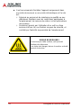
CAUTION:
Information to prevent minor physical injury, component dam-
age, data loss, and/or program corruption when trying to com-
plete a task.
Information to prevent serious physical injury, component
damage, data loss, and/or program corruption when trying to
complete a specific task.

v
PXES-2788 Series
Table of Contents
Revision History...................................................................... ii
Preface.................................................................................... iii
List of Figures....................................................................... vii
List of Tables.......................................................................... ix
1 Introduction ........................................................................ 1
1.1 Features............................................................................... 2
1.2 Specifications....................................................................... 3
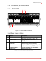
1.3 Connectors, I/O and Controls ............................................ 17
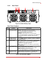
1.3.1 Front Panel ............................................................... 17
1.3.2 Rear Panel................................................................ 19
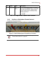
1.3.3 Positions of Backplane Thermal Sensors................. 21
1.3.4 PCI Express.............................................................. 22
2 Getting Started ................................................................. 31
2.1 Package Contents ............................................................. 31
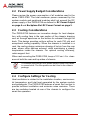
2.2 Power Supply Budget Considerations ............................... 32
2.3 Cooling Considerations...................................................... 32
2.4 Configure Settings for Cooling........................................... 32
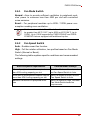
2.4.1 Fan Mode Switch...................................................... 33
2.4.2 Fan Speed Switch .................................................... 33
2.5 Hardware Installation ......................................................... 34
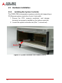
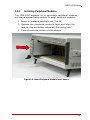
2.5.1 Installing the System Controller................................ 34
2.5.2 Installing Peripheral Modules ................................... 39
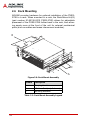
2.6 Rack Mounting................................................................... 42
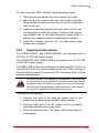
2.6.1 Powering Up the System .......................................... 43
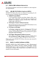
2.7 PXES-2788 Software Resources....................................... 44
2.7.1 ADLINK PXI Platform Services (APPS).................... 44
2.7.2 MAPS Core DAQ Software & Utility ......................... 44

vi
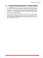
3 System Management & Configuration............................ 45
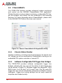
3.1 ChassisWatch .................................................................... 46
3.1.1 Chassis Status Monitor............................................. 46
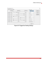
3.1.2 Software Configurable PXI Trigger Bus Bridges....... 46
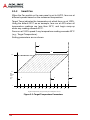
3.1.3 Smart Fan ................................................................. 48
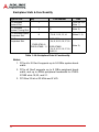
A Appendix: Maintenance.....................................................51
A.1 Installation Problems.......................................................... 51
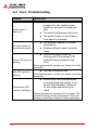
A.2 Basic Troubleshooting ....................................................... 52
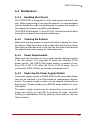
A.3 Maintenance ...................................................................... 53
A.3.1 Handling the Chassis................................................ 53
A.3.2 Cleaning the Exterior ................................................ 53
A.3.3 Power Requirements ................................................ 53
A.3.4 Replacing the Power Supply Module........................ 53
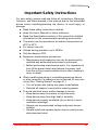
Important Safety Instructions............................................... 55
Consignes de Sécurité Importante...................................... 58
Getting Service...................................................................... 61

List of Figures vii
PXES-2788 Series
List of Figures
Figure 1-1: Backplane PCI Express Bus Topology....................... 9
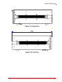
Figure 1-2: Front View ................................................................ 12
Figure 1-3: Right View ................................................................ 13
Figure 1-4: Left View................................................................... 13
Figure 1-5: PXES-2788 Front Panel ........................................... 17
Figure 1-6: PXES-2788 Rear Panel............................................ 19
Figure 1-7: PXES-2788 Backplane Thermal Sensor Positions... 21
Figure 1-8: Star Trigger & Differential Star Bus Routing............. 23
Figure 1-9: 3U Hybrid Slot Compatible PXI-1 Peripheral Module25
Figure 1-10: 3U PXI Express Peripheral Module .......................... 26
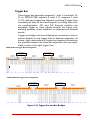
Figure 1-11: Trigger Bus and Bus Bridges.................................... 27
Figure 1-12: Trigger Bus Bridge Routing ...................................... 28
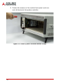
Figure 2-1: System Controller Slot Location (Slot 1)................... 34
Figure 2-2: Depress Module Release Latch ............................... 35
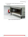
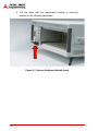
Figure 2-3: Align System Controller Module ............................... 36
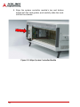
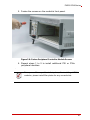
Figure 2-4: Secure System Controller Module Latch .................. 37
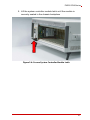
Figure 2-5: Fasten System Controller Module Screws ............... 38
Figure 2-6: Insert Peripheral Module into Chassis...................... 39
Figure 2-7: Secure Peripheral Module Latch .............................. 40
Figure 2-8: Fasten Peripheral Controller Module Screws ........... 41
Figure 2-9: Rack Mount Assembly.............................................. 42
Figure 3-1: Chassis ChassisWatch GUI Application Utility ......... 46
Figure 3-2: Trigger Bus Routing Settings.................................... 47
Figure 3-3: Target Temperature Parameters .............................. 48

viii List of Figures
This page intentionally left blank.

List of Tables ix
PXES-2788 Series
List of Tables
Table 1-1: Power Supply Specifications ........................................... 3
Table 1-2: DC Power Output Specifications ..................................... 5
Table 1-3: Backplane Slot DC Power Current .................................. 5
Table 1-4: PXI 10 MHz Reference Clock .......................................... 6
Table 1-5: 10MHz Clock Output: Front Panel SMA Output .............. 6
Table 1-6: 10MHz Clock Input: Front Panel SMA Connector ........... 6
Table 1-7: PXI Star Trigger ............................................................... 7
Table 1-8: PXI Express 100 MHz System Reference Clock ............. 7
Table 1-9: PXI Differential Star Triggers ........................................... 7
Table 1-10: Backplane Slots & Functionality ...................................... 8
Table 1-11: Cooling Capacity............................................................ 10
Table 1-12: Cooling .......................................................................... 11
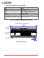
Table 1-13: Mechanical Dimensions and Weight.............................. 12
Table 1-14: PXI Express Slot Pin Definitions.................................... 14
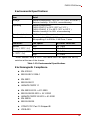
Table 1-15: Environmental Specifications......................................... 15
Table 1-16: Front Panel Power & Status .......................................... 17
Table 1-17: Front Panel Indicators.................................................... 18
Table 1-18: Rear Panel Legend........................................................ 19
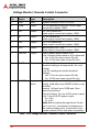
Table 1-19: Voltage Monitor / Remote Control Connector................ 20
Table 1-20: Star Trigger & Differential Star Bus Assignments.......... 24
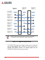
Table 1-21: PXES-2788 Reference Clock Priority ............................ 29
Table 2-1: Rack Mount Assembly Legend ...................................... 42
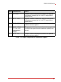
Table 3-1: Target Temperature Parameters Legend ...................... 49

x List of Tables
This page intentionally left blank.

1
PXES-2788 Series
1 Introduction
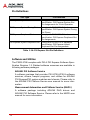
Get ready to take your testing and measurement applications to
the next level with the ADLINK PXES-2788 Series chassis. With
its high-performance 18-slot PXI Express backplane, high-output
power supply, and cooling capacity, it's designed for heavy-duty
and high port density applications. The modular design ensures a
high level of maintainability, with replaceable power supplies for
high-availability applications, resulting in a very low meantime to
repair (MTTR).
Fully compliant with the PXI-5 PXI Express hardware specifica-
tion, the PXES-2788 Series offers advanced timing and synchroni-
zation features for high clock accuracy and external clock and
trigger routing. Using PCI Express 3.0 technology, the chassis
boasts a system bandwidth of up to 24GB/s for high-throughput,
peer-to-peer data transfer applications, and up to 8 GB/s band-
width for all peripheral slots.
The PXES-2788 Series provides up to 102W power and cooling
capacity per slot, allowing for higher power budgets for high-per-
formance and power PXI modules. And with a smart system moni-
toring controller that reports chassis status, including fan speed,
system voltages, and internal temperature, you can be sure that
your system is running at optimal performance. The smart fan
function dynamically adjusts fan speed based on the embedded
temperature sensor to achieve a balance between sufficient air-
flow and operating noise.
Experience the power and versatility of the ADLINK PXES-2788
Series chassis and take your testing and measurement applica-
tions to the next level.

2
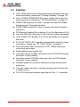
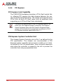
1.1 Features
XUp to 102W power and cooling capacity per peripheral slot (for
more information, please see “Cooling Capacity” on page 10.)
XUp to 1700W/1000W/800W DC power supply total output (for
more information, please see “DC Power Output” on page 4.)
XPXES-2788 supports 18 slots (1 system slot with left-3-blank-
slot space and 18 peripheral slots)
XPXES-2788E supports 21 slots (1 system slot and 20 periph-
eral slots)
XPXI Express System Slot routed as 2 Link Configuration x8 x16
XUp to 24 GB/s (PCI Express 3.0 x8 x16 link) system bandwidth
XUp to 8 GB/s (PCI Express 3.0 x8 link) bandwidth for all periph-
eral slots
X0°C to 55°C/50°C/45°C operating temperature range (for more
information, please see “DC Power Output” on page 4.)
XTwo front panel SMA connectors for PXI 10MHz reference
clock input and output
XReplaceable power supply unit
XLow-jitter internal 10 MHz reference clock for PXI/PXI Express
slots with ±1 ppm stability
XLow-jitter internal 100 MHz reference clock for PXI Express
slots with ±1 ppm stability
XVariable speed fan controller optimizes cooling and acoustic
emissions
XThrough inhibit connector, including remote power button and
voltage monitor
XPXI-5 PXI Express hardware specification Rev. 1.1 compliant

3
PXES-2788 Series
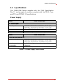
1.2 Specifications
The PXES-2788 Series complies with the PXI-5 Specification
Rev.1.1 and accepts all modules compliant with the PXI-5, Com-
pactPCI, and PICMG 2.0 specifications.
Power Supply
Table 1-1: Power Supply Specifications
Model PXES-2788/2788E
AC Power Input
Rated Input 2400 PSU: 200-240V AC, 50/60Hz, 13.3A (X2)
1300 PSU: 100-240V AC, 50-60Hz, 12-7A (X2)
Over-current protection Internal AC in-line fuse (non user serviceable)
Dual PSU Slots Current sharing mode, not hot swappable.
Model PXES-2788/2788E
Entrée d'alimentation CA
Entrée nominale 2400 PSU: 200-240V AC, 50/60Hz, 13.3A (X2)
1300 PSU: 100-240V AC, 50-60Hz, 12-7A (X2)
Protection contre les
surintensités Fusible AC en ligne interne (non réparable par
l'utilisateur).
Double PSU Mode de partage actuel, non remplaçable à chaud.

4
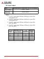
DC Power Output
Notes:
1. 0 to 45°C, input power 200Vac to 240Vac for in-box PSU
CSU2400AP-3-XX.
2. 0 to 50°C, input power 200Vac to 240Vac for in-box PSU
CSU2400AP-3-XX.
3. 0 to 55°C, input power 200Vac to 240Vac for in-box PSU
FSP1300-29FM.
4. 0 to 55°C, input power 100Vac to 120Vac for in-box PSU
FSP1300-29FM
Model Maximum total DC output power (for all PXIe modules)
PXES-2788/HP
PXES-2788E/HP
1700W1 / 1000W2
PXES-2788
PXES-2788E
1000W3 / 800W4
DC Power
Voltage
Maximum Current
Per Chassis1
(Total of All Slots)
Load
Regulation
Maximum
Ripple
Noise
+12V 72A ±5% 120mV
+3.3V 77A ±5% 50mV
+5V 20A ±5% 50mV
-12V 4A ±5% 120mV
+5Vsb 4A ±5% 50mV

5
PXES-2788 Series
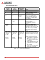
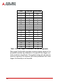
Table 1-2: DC Power Output Specifications
Backplane Slot DC Power Current
Note: For more information, please see “DC Power Output” on
page 4.
Table 1-3: Backplane Slot DC Power Current
DC Power
Voltage Maximum Current Per Slot1
1.Applies to all PXES-2788 SKUs (PXES-2788/HP, PXES-
2788E/HP, PXES-2788, PXES-2788E).
Slot Type PXIe
System
Slot
PXIe Peripheral Slot
PXIe System Timing Slot PXIe Hybrid
Peripheral Slot
+12V 30A 6A 6A
+3.3V 15A 9A 9A
+5V 15A - 6A
-12V - - 1A
+5Vsb 3A 1A (Shared)
Slot Type Slot Number +5V +3.3V +12V -12V +5Vaux
PXIe System Slot 1 15A 15A 30A - 3A
PXIe Peripheral/
System Timing
Slots
PXES-2788:
2,3,4,5,10,15,16,17,18
PXES-2788E:
2,3,4,5,10,15,16,17,18,
19,20,21
-9A6A - 1A
PXIe Hybrid
Peripheral Slot 6,7,8,9,11,12,13,14 6A 9A 6A 1A 1A

6
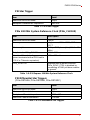
PXI 10 MHz System Reference Clock (PXI_CLK10)
Table 1-4: PXI 10 MHz Reference Clock
10MHz Clock Output: Front Panel SMA Connector
Table 1-5: 10MHz Clock Output: Front Panel SMA Output
10MHz Clock Input Requirements: Front Panel SMA Con-
nector
Table 1-6: 10MHz Clock Input: Front Panel SMA Connector
Item Detail
Maximum slot-to-slot skew 280 ps
Accuracy ±1 ppm max, 0°C to 55°C, 32˚F to 131˚F
Maximum jitter 0.44 ps RMS phase-jitter (12k Hz–20 MHz)
Duty-factor for PXI_CLK10 45% to 55%
Unloaded signal swing 3.3V ± 5% (±0.165V)
Item Detail
Accuracy ±1 ppm max, 0°C to 55°C, 32˚F to 131˚F
Maximum jitter 2.14 ps RMS phase-jitter (12k Hz–20 MHz)
Output amplitude 1 Vpp ±20% square-wave into 50,
2 Vpp unloaded
Output impedance 50 ±5
Item Detail
Frequency input 10 MHz ±25 PPM
Input signal (10MHz REF In SMA) 100 mVPP to 5 VPP
(square or sine)
Input impedance (10MHz REF In SMA) High impedance
Input signal (PXI_CLK10_IN on 10th slot) 5 V or 3.3 V TTL signal

7
PXES-2788 Series
PXI Star Trigger
Table 1-7: PXI Star Trigger
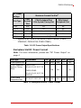
PXIe 100 MHz System Reference Clock (PXIe_CLK100)
Table 1-8: PXI Express 100 MHz System Reference Clock
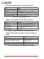
PXI Differential Star Triggers
(PXIe-DSTARA, PXIe-DSTARB, PXIe-DSTARC)
Table 1-9: PXI Differential Star Triggers
Item Detail
Maximum slot-to-slot skew 250ps
Backplane characteristic impedance 50 ±5
Item Description
Maximum slot-to-slot skew 100 ps
Accuracy ±1 ppm max, 0°C to 55°C , 32˚F to
131˚F
Maximum jitter 2.41 ps RMS phase-jitter (12k Hz–20
MHz)
Duty-factor for PXIe_CLK100 45% to 55%
Absolute differential voltage
(when terminated with a 50 load to
1.30 V or Thévenin equivalent)
400 to 900 mV
PXIe_SYNC100 Implemented as default behavior.
PXIe_SYNC_CTRL is disabled by
connecting a 10k pull-down resistor
to ground.
Item Detail
Maximum slot-to-slot skew 150ps
Maximum differential skew 25ps
Backplane differential impedance 100 ±10
Maximum Channel Bandwidth 1.75GHz

8
Backplane Slots & Functionality
Table 1-10: Backplane Slots & Functionality
Notes:
1. PCIe x8 x16 Gen3 supports up to 24 GB/s system band-
width.
2. PCIe x8 Gen3 supports up to 8 GB/s peripheral band-
width, and up to 4GB/s peripheral bandwidth for PXES-
2788E slots 19,20, and 21.
3. PCI Bus 32-bit at 33 MHz and 5 VIO.
Type of Slot Qty Slot Number Bus
PXI Express
System Slot
1 1 2 Link x8 x16
(Note 1)
PXI Express
System Timing Slot 110 (Note 2)
PXI Express Hybrid
Peripheral Slot 8 6,7,8,9,11,12,13,14 (Notes 2, 3)
PXI Express
Peripheral Slot
PXES-2788: 8
PXES-2788E: 11
PXES-2788:
2,3,4,5,10,15,16,17,18
PXES-2788E:
2,3,4,5,10,15,16,17,18,
19,20,21
(Note 2)

9
PXES-2788 Series
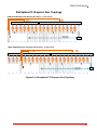
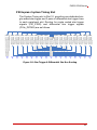
Backplane PCI Express Bus Topology
Figure 1-1: Backplane PCI Express Bus Topology
Sl ot 01 Slot 02 Slot 03 Sl ot 04 Sl ot 05 Sl ot 06 Sl ot 07 Sl ot 08 Sl ot 09 Sl ot 10 Sl ot 11 Sl ot 12 Sl ot 13 Sl ot 14 Sl ot 15 Sl ot 16 Sl ot 17 Sl ot 18
PCI Express Switch Fabric PCI Express Switch Fabric
Gen3
x8
Gen3
x16
PXES-2788 Backplane PCI Express Bus Fabric - 2 Link x16 x8
PCIe To
PCI Br idge
Gen3
x8
Gen3
x8
Gen3
x8
Gen3
x8
Gen3
x8
Gen3
x8
Gen3
x8
Gen3
x8
Gen3
x8
Gen3
x8
Gen3
x8
Gen3
x8
Gen3
x8
Gen3
x8
Gen3
x8
Gen3
x8
Gen3
x8
Gen1
x1
PCI Bus 32bit
(33MHz 5VIO)
Sl ot 01 Slot 02 Sl ot 03 Sl ot 04 Sl ot 05 Sl ot 06 Slot 07 Sl ot 08 Sl ot 09 Sl ot 10 Sl ot 11 Sl ot 12 Sl ot 13 Sl ot 14 Sl ot 15 Slot 16 Sl ot 17 Sl ot 18
PCI Express Switch Fabric PCI Express Switch Fabric
Gen3
x8
Gen3
x16
PXES-2788E Backplane PCI Express Bus Fabric - 2 Link x16 x8
PCIe To
PCI Br idge
Gen3
x8
Gen3
x8
Gen3
x8
Gen3
x8
Gen3
x8
Gen3
x8
Gen3
x8
Gen3
x8
Gen3
x8
Gen3
x8
Gen3
x8
Gen3
x8
Gen3
x8
Gen3
x8
Gen3
x8
Gen3
x8
Gen3
x8
Gen1
x1
PCI Bus 32bit
(33MHz 5VIO)
Sl ot 19 Sl ot 20 Sl ot 21
Gen3
x4
Gen3
x4
Gen3
x4

10
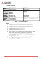
Cooling Capacity
Table 1-11: Cooling Capacity
Notes:
1. Ambient temperature: 0°C to 40°C, boost fan mode.
2. Ambient temperature: 0°C to 45°C, boost fan mode.
3. Ambient temperature: 0°C to 50°C.
4. Ambient temperature: 0°C to 55°C.
5. When all slots have installed high power peripheral mod-
ules (>60W), the cooling requirements of modules
installed in slots 2, 3, 7, 8, 9, 17, 18, 19, 20 shall be lim-
ited to less than 72W.
6. For DC power supply for modules, please see “DC
Power Output” on page 4
Model PXES-2788/HP
PXES-2788E/HP
PXES-2788
PXES-2788E
Per
Peripheral
Slot (Max)
102W/slot1, 5
85W/slot2, 5
60W/slot3
85W/slot2, 5
60W/slot4
System
Slot (Max) 200W/sys slot2
150W/sys slot3
200W/sys slot2
150/sys slot4
Chassis
(Max) 1700W/chassis2
1350W/chassis31700W/chassis1, 1350W/chassis4
La page est en cours de chargement...
La page est en cours de chargement...
La page est en cours de chargement...
La page est en cours de chargement...
La page est en cours de chargement...
La page est en cours de chargement...
La page est en cours de chargement...
La page est en cours de chargement...
La page est en cours de chargement...
La page est en cours de chargement...
La page est en cours de chargement...
La page est en cours de chargement...
La page est en cours de chargement...
La page est en cours de chargement...
La page est en cours de chargement...
La page est en cours de chargement...
La page est en cours de chargement...
La page est en cours de chargement...
La page est en cours de chargement...
La page est en cours de chargement...
La page est en cours de chargement...
La page est en cours de chargement...
La page est en cours de chargement...
La page est en cours de chargement...
La page est en cours de chargement...
La page est en cours de chargement...
La page est en cours de chargement...
La page est en cours de chargement...
La page est en cours de chargement...
La page est en cours de chargement...
La page est en cours de chargement...
La page est en cours de chargement...
La page est en cours de chargement...
La page est en cours de chargement...
La page est en cours de chargement...
La page est en cours de chargement...
La page est en cours de chargement...
La page est en cours de chargement...
La page est en cours de chargement...
La page est en cours de chargement...
La page est en cours de chargement...
La page est en cours de chargement...
La page est en cours de chargement...
La page est en cours de chargement...
La page est en cours de chargement...
La page est en cours de chargement...
La page est en cours de chargement...
La page est en cours de chargement...
La page est en cours de chargement...
La page est en cours de chargement...
La page est en cours de chargement...
-
 1
1
-
 2
2
-
 3
3
-
 4
4
-
 5
5
-
 6
6
-
 7
7
-
 8
8
-
 9
9
-
 10
10
-
 11
11
-
 12
12
-
 13
13
-
 14
14
-
 15
15
-
 16
16
-
 17
17
-
 18
18
-
 19
19
-
 20
20
-
 21
21
-
 22
22
-
 23
23
-
 24
24
-
 25
25
-
 26
26
-
 27
27
-
 28
28
-
 29
29
-
 30
30
-
 31
31
-
 32
32
-
 33
33
-
 34
34
-
 35
35
-
 36
36
-
 37
37
-
 38
38
-
 39
39
-
 40
40
-
 41
41
-
 42
42
-
 43
43
-
 44
44
-
 45
45
-
 46
46
-
 47
47
-
 48
48
-
 49
49
-
 50
50
-
 51
51
-
 52
52
-
 53
53
-
 54
54
-
 55
55
-
 56
56
-
 57
57
-
 58
58
-
 59
59
-
 60
60
-
 61
61
-
 62
62
-
 63
63
-
 64
64
-
 65
65
-
 66
66
-
 67
67
-
 68
68
-
 69
69
-
 70
70
-
 71
71


Adlink PXES-2788 Series Le manuel du propriétaire
- Catégorie
- Cartes / adaptateurs d'interface
- Taper
- Le manuel du propriétaire