Adlink MECS-7211 Le manuel du propriétaire
- Taper
- Le manuel du propriétaire

MECS-7211
2U Edge Computing Server
with Dual Intel® Xeon® Processor
User’s Manual
Manual Rev.: Rev.1.1
Revision Date: July 28, 2023
Part No.: 50M-F0090-1010

2
MECS-7211
Preface
Copyright © 2022-2023 ADLINK Technology, Inc.
This document contains proprietary information protected by copyright. All rights are
reserved. No part of this manual may be reproduced by any mechanical, electronic, or other
means in any form without prior written permission of the manufacturer.
Disclaimer
The information in this document is subject to change without prior notice in order to improve
reliability, design, and function and does not represent a commitment on the part of the
manufacturer.
In no event will the manufacturer be liable for direct, indirect, special, incidental, or
consequential damages arising out of the use or inability to use the product or
documentation, even if advised of the possibility of such damages.
Environmental Responsibility
ADLINK is committed to fulfill its social responsibility to global
environmental preservation through compliance with the European
Union's Restriction of Hazardous Substances (RoHS) directive and
Waste Electrical and Electronic Equipment (WEEE) directive.
Environmental protection is a top priority for ADLINK. We have enforced
measures to ensure that our products, manufacturing processes,
components, and raw materials have as little impact on the environment
as possible. When products are at their end of life, our customers are
encouraged to dispose of them in accordance with the product disposal and/or recovery
programs prescribed by their nation or company.
Trademarks
Product names mentioned herein are used for identification purposes only and may be
trademarks and/or registered trademarks of their respective companies.
Revision History
Revision Release Date Description of Change(s)
1.0 2022-11-22 Initial release
1.1 2023-07-28 Add DC power supply polarity and ground info.
Previous revision: P/N 50M-00046-1000

3
MECS-7211
Conventions
Information to prevent serious physical injury, component damage, data
loss, and/or program corruption when trying to complete a specific task.
Informations destinées à prévenir les blessures corporelles graves, les
dommages aux composants, la perte de données et/ou la corruption de
programme lors de l'exécution d'une tâche spécifique.
A
VERTISSEMENT
Information to prevent minor physical injury, component damage, data
loss, and/or program corruption when trying to complete a task.
Informations destinées à prévenir les blessures corporelles mineures,
les dommages aux composants, la perte de données et/ou la corruption
de programme lors de l'exécution d'une tâche.
mise en garde

4
MECS-7211
Table of Contents
Preface .................................................................................................................................. 2
1 Overview .......................................................................................................................... 6
1.1 Introduction .............................................................................................................................. 6
1.1 Block Diagram.......................................................................................................................... 7
1.2 Mechanical Overview............................................................................................................... 8
1.2.1 Front Panel ........................................................................................................................................8
1.2.2 Rear Panel.........................................................................................................................................8
1.2.3 Chassis Layout ..................................................................................................................................9
1.3 Mechanical Dimensions ......................................................................................................... 10
2 Specifications .................................................................................................................11
2.1 MECS-7211 Specifications......................................................................................................11
3 Getting Started............................................................................................................... 13
3.1 Removing the Chassis Cover ................................................................................................ 13
3.2 Installing Memory Modules .................................................................................................... 14
3.3 PCIe x16 Slot FHFL Card Installation .................................................................................... 15
3.4 PCIe x8 HHHL Slot Card Installation ..................................................................................... 19
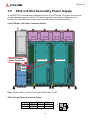
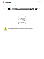
3.5 PCIe x16 Slot Secondary Power Supply................................................................................ 21
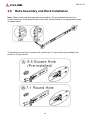
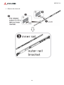
3.6 Rails Assembly and Rack Installation .................................................................................... 23
3.7 Uninstalling the Rails from the Chassis.................................................................................. 27
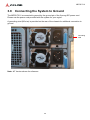
3.8 Connecting the System to Ground......................................................................................... 30
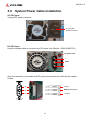
3.9 System Power Cable Installation ........................................................................................... 31
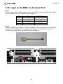
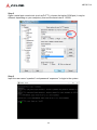
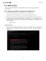
3.10 Login to the BMC via Console Port...................................................................................... 32
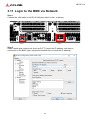
3.11 Login to the BMC via Network.............................................................................................. 34
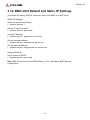
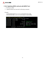
3.12 BMC eth0 Default and Static IP Settings.............................................................................. 36
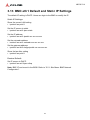
3.13 BMC eth1 Default and Static IP Settings.............................................................................. 37
3.14 BIOS Update........................................................................................................................ 38
3.14.1 Updating the BIOS via Network with BMC Tool...............................................................................38
3.14.2 Updating BIOS via Host with BIOS Tool..........................................................................................40
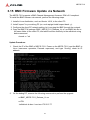
3.15 BMC Firmware Update via Network..................................................................................... 41
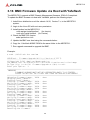
3.16 BMC Firmware Update via Host with Yafuflash ................................................................... 42
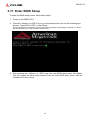
3.17 Enter BIOS Setup ................................................................................................................44
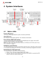
4 System Interfaces.......................................................................................................... 45
4.1 Status LEDs ........................................................................................................................... 45
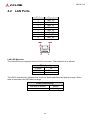
4.2 LAN Ports............................................................................................................................... 46
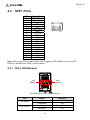
4.3 SFP+ Ports............................................................................................................................. 47
4.3.1 SFP+ LED Behavior ........................................................................................................................47
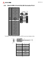
4.4 Dual USB 3.0 and RJ-45 Console Port.................................................................................. 48
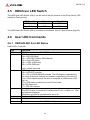
4.5 HDD/User LED Switch ........................................................................................................... 49
4.6 User LED Commands ............................................................................................................ 49
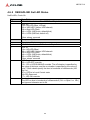
4.6.1 OEM ADLINK Set LED Status .........................................................................................................49
4.6.2 OEM ADLINK Get LED Status.........................................................................................................50
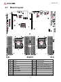
4.7 Board Layout.......................................................................................................................... 51

5
MECS-7211
5 BIOS Setup..................................................................................................................... 52
5.1 BIOS Setup Menu .................................................................................................................. 52
5.1.1 Menu Selection Bar .........................................................................................................................52
5.1.2 Menu Conventions...........................................................................................................................53
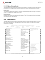
5.2 Main Menu ............................................................................................................................. 53
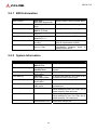
5.2.1 BIOS Information .............................................................................................................................54
5.2.2 System Information..........................................................................................................................54
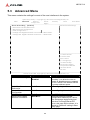
5.3 Advanced Menu ..................................................................................................................... 55
5.3.1 Sub-Menu: Serial Port Console Redirection....................................................................................56
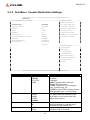
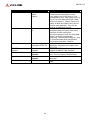
5.3.2 Sub-Menu: Console Redirection Settings .......................................................................................57
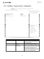
5.3.3 Sub-Menu: Legacy Console Configuration.....................................................................................59
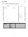
5.3.4 Sub-Menu: Network Stack Configuration ........................................................................................60
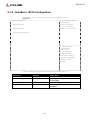
5.3.5 Sub-Menu: iSCSI Configuration ......................................................................................................61
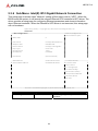
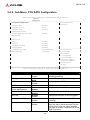
5.3.6 Sub-Menu: Intel(R) I210 Gigabit Network Connection ....................................................................62
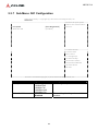
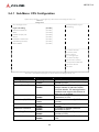
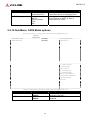
5.3.7 Sub-Menu: NIC Configuration .........................................................................................................63
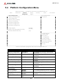
5.4 Platform Configuration Menu ................................................................................................. 64
5.4.1 Sub-Menu: CPU Configuration ........................................................................................................65
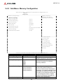
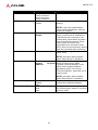
5.4.2 Sub-Menu: Memory Configuration...................................................................................................66
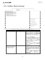
5.4.3 Sub-Menu: Memory Topology..........................................................................................................68
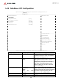
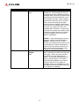
5.4.4 Sub-Menu: UPI Configuration..........................................................................................................69
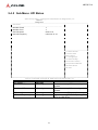
5.4.5 Sub-Menu: UPI Status .....................................................................................................................71
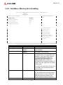
5.4.6 Sub-Menu: Memory Error Enabling.................................................................................................72
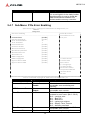
5.4.7 Sub-Menu: PCIe Error Enabling ......................................................................................................73
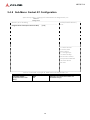
5.4.8 Sub-Menu: Socket 0/1 Configuration ..............................................................................................75
5.4.9 Sub-Menu: PCH SATA Configuration ..............................................................................................76
5.4.10 Sub-Menu: SATA Mode options.......................................................................................................77
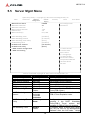
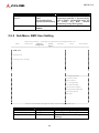
5.5 Server Mgmt Menu ................................................................................................................78
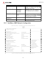
5.5.1 Sub-Menu: BMC Network Configuration .........................................................................................79
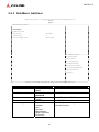
5.5.2 Sub-Menu: BMC User Setting .........................................................................................................80
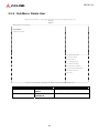
5.5.3 Sub-Menu: Add User .......................................................................................................................81
5.5.4 Sub-Menu: Delete User ...................................................................................................................82
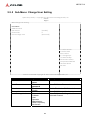
5.5.5 Sub-Menu: Change User Setting.....................................................................................................83
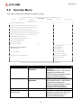
5.6 Security Menu ........................................................................................................................ 84
5.6.1 Sub-Menu: Secure Boot ..................................................................................................................86
5.6.2 Sub-Menu: Key Management..........................................................................................................87
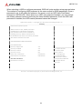
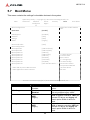
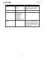
5.7 Boot Menu.............................................................................................................................. 88
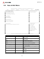
5.8 Save & Exit Menu .................................................................................................................. 90
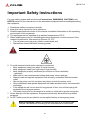
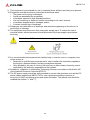
Important Safety Instructions............................................................................................ 91
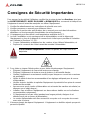
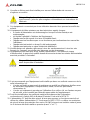
Consignes de Sécurité Importantes ................................................................................. 93
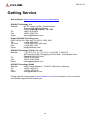
Getting Service ................................................................................................................... 95

6
MECS-7211
1 Overview
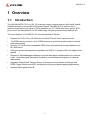
1.1 Introduction
The ADLINK MECS-7211 is a 2U 19" rackmount edge computing server with Intel® Xeon®
Scalable processor and Intel® C620 Series Chipset. The MECS-7211 features an IO
intensive architecture with up to 5x PCIe interfaces, 4x 2.5’’ SATA drive bays, and 4x SFP+
ports, and is an ideal platform for 5G mobile edge computing infrastructure deployment.
The main features of the MECS-7211 are summarized as follows:
• Supports 4x FHFL PCIe x16 Gen3 and 1x HHHL PCIe x8 Gen3 expansion slots
• 16x DDR4 memory slots for up to 512GB memory to meet the requirements of network
packet processing
• Up to 4x 2.5" external hot-swappable SATA drives and additional storage expansion via
M.2 SATA drive
• Intelligent system management compatible with IPMI 2.0, supports SOL and adaptive fan
speeds
• Support for PacketManager software to provide data plane software stacks for dynamic
Layer 3 forwarding and flow-based forwarding, accelerating development of customer
applications
• Integrates Wind River® Titanium Server, and open source software including Intel®
DPDK, Open vSwitch and nDPI, facilitating the building of packet parsing applications
• Supports EMC grade Class B

7
MECS-7211
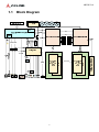
1.1 Block Diagram

8
MECS-7211
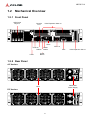
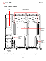
1.2 Mechanical Overview
1.2.1 Front Panel
1.2.2 Rear Panel
AC Version:
DC Version:
LEDs
SATA Drive
Bays x4 Console
Port
VGA
RJ45 x2 SFP+ x4
USB x2
Power
Button
Reset
Button
PCIe Expansion Slots x4
PCIe Expansion Slot x1
LEDs
Redundant
Power Supply
Fans


10
MECS-7211
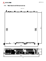
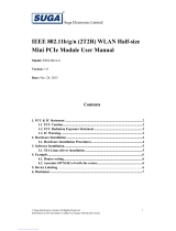
1.3 Mechanical Dimensions
Units: mm
448
454
87
481

11
MECS-7211
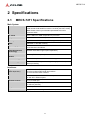
2 Specifications
2.1 MECS-7211 Specifications
Main System
CPU Intel® Xeon® Gold 5218R Processor 2.10 GHz (20C/40T, 125W)
Intel® Xeon® Gold 5220R Processor 2.20 GHz (24C/48T, 150W)
Note: Please contact your ADLINK representative for other
processor SKUs.
L3 Cache From 11MB to 24.75MB, dependent on processor
Chipset Intel® C624/C625/C627 Chipset
Memory 16x DDR4-2666 DIMM sockets, ECC, registered, up to 512GB
BIOS AMI BIOS on SPI flash memory
Operating System Windows 7 64-bit, Windows 10 64-bit, Windows Server 2016,
Linux Kernel 2.6 and above
Intel® QuickAssist
Technology
100Gb/s Intel® QAT support (SKU dependent)
Trusted Platform
Module
TPM 1.2 (TPM 2.0 optional)
Chassis Management IPMI v2.0 compliant with iKVM and SOL support
Software Support Validated with DPDK, provides a high throughput for data plane
packet processing
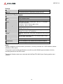
Interfaces
Expansion
(SKU dependent)
4x PCIe x16 Gen3 FHFL single-slot interface or
2x PCIe x16 Gen3 FHFL dual-slot interface
1x PCIe x8 Gen3 HHHL interface
Ethernet 2x RJ-45 10/100/1000BASE-T Ethernet ports
4x 10G SFP+ Ethernet ports
Remote Console 1x RJ-45 serial port
USB 2x USB 3.0 (front panel)
1x USB 3.0 (internal)
Graphics 1x VGA port
LEDs Power, Alert, Drive Activity, Health Behavior, UID

12
MECS-7211
Storage
Drive Bays 4x 2.5’’ external hot-swappable SATA 6 Gb/s drive bays
Internal 1x onboard M.2 2242 or 2280 M-key SATA 6 Gb/s slot
Mechanical & Environmental
Form Factor 2U 19’’ rackmount 438mm x 88mm x 450mm (W x H x D)
Fans 4 fans, adaptive speed
Weight1 13 kg net
Power 800W (EMC class B) or 1200W (EMC class A), 1+1 redundant
PSU (SKU dependent)
AC Version: 100V to 240V AC @50–60 Hz
DC Version: -40V to -72V DC
Temperature2 Operating: -5°C 55°C
Storage: -40°C to 70°C
Humidity2 Operating: 10% to 85% @40°C, non-condensing
Storage: 5% to 90%, non-condensing
Operating: half-sine 2G, 11ms pulse, 100 pulses on each of three
axes
Shock3
Non-operating: trapezoidal, 25G, 170 inches/sec delta V, three
drops on each of three axes
Vibration3 Non-operating: 2.2Grms, 10 minutes per axis on all three axes
Certifications FCC, CE emissions, CCC class B, CB, and RoHS compliant
MTBF 798789 hours @ 25°C (TBC)
Notes:
1System weights are measured with 2 processors, 4 memory modules and 1 SSD installed, without
rail slides or PCIe cards
2Temperature and humidity specifications are valid only with ADLINK approved add-on devices,
excluding hard drives and PCIe cards.
3Shock and Vibration tests were conducted with WinFast RTX 2060 Super Classic graphics card
installed.

13
MECS-7211
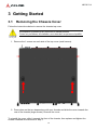
3 Getting Started
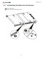
3.1 Removing the Chassis Cover
Follow the instructions below to remove the chassis top cover.
1. Remove the 1 screws on each side of the top cover (small arrows).
2. Press down on the two depressions with your thumbs and slide the cover towards the
rear of the chassis (large arrows). Remove the cover.
To reinstall the cover, slide it towards the front of the chassis, then replace and tighten the
screws loosened and removed in Step 1.
All installation procedures are restricted to skilled persons.
Toutes les procédures d'installation sont réservées au personnel qualifié.
mise en garde

14
MECS-7211
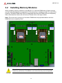
3.2 Installing Memory Modules
When installing memory modules in the MECS-7211, the blue DIMM slots of each channel
can be freely populated (it is suggested to fill the slots from “outside to inside” for each CPU).
However, the black DIMM slots must be populated after the blue DIMM slots are completely
filled, otherwise the device will not boot up. Please refer to the figure below.
Note: The device will not boot up if the black DIMM slots are populated before the blue
DIMM slots are completely filled.
CPU0 CPU1
Blue
Blue
Blue
Black
Blue
Blue
Blue
Black
Blue
Blue
Blue
Black
Blue
Blue
Blue
Black
All installation procedures are restricted to qualified personnel.
Toutes les procédures d'installation sont réservées au personnel qualifié.
mise en garde

15
MECS-7211
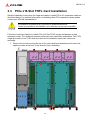
3.3 PCIe x16 Slot FHFL Card Installation
Sample installation instructions for single-slot-passive cooled PCIe x16 expansion cards are
described below. For detailed information on installing other PCIe expansion cards, please
contact your ADLINK representative.
Follow the instructions below to install PCIe x16 Gen3 FHFL single-slot-passive cooled
expansion cards. The cards are mounted inside two riser-card/cover assemblies. Two FHFL
single-slot cards or one FHFL dual-slot card can be installed in each riser-card/cover
assembly.
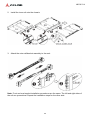
1. Remove the screw securing the top of the riser-card/cover assembly and loosen the
captive screws at the front of the chassis (2 per assembly).
All installation procedures are restricted to qualified personnel.
Toutes les procédures d'installation sont réservées au personnel qualifié.
mise en garde

16
MECS-7211
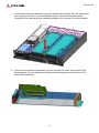
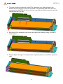
2. Lift the riser-card/cover assembly using the handle as indicated. This will remove the
riser card from the slot on the motherboard which is directly below the handle.
Carefully lift the riser-card/cover assembly straight up to remove it from the chassis.
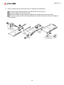
3. Turn the riser-card/cover assembly over and remove the screw securing the PCIe
blanking plate from the desired slot. Remove the blanking plate from the front I/O
panel of the assembly.

17
MECS-7211
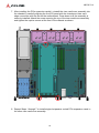
4. To install a single-slot-passive cooled PCIe expansion card, align the tab on the
bracket with the opening on the front I/O panel of the assembly and insert the PCIe
connectors into the PCIe x16 slot on the riser card. Make sure the connectors are fully
inserted into the PCIe slot.
5. Secure the PCIe expansion card to the riser-card/cover assembly using 1 screw as
shown below.
6. Repeat Steps 3 through 5 to install another single-slot-passive cooled PCIe expansion
card.

18
MECS-7211
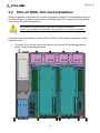
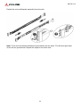
7. After installing the PCIe expansion card(s), reinstall the riser-card/cover assembly into
the chassis by carefully aligning the front I/O panel with the chassis and riser card
edge connectors with the slot on the motherboard. Press down until the assembly is
securely installed. Attach the screw securing the top of the riser-card/cover assembly
and tighten the captive screws at the front of the chassis as shown.
8. Repeat Steps 1 through 7 to install single-slot-passive cooled PCIe expansion cards in
the other riser-card/cover assembly.

19
MECS-7211
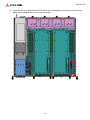
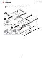
3.4 PCIe x8 HHHL Slot Card Installation
Sample installation instructions for a single-slot-passive cooled PCIe x8 expansion card are
described below. For detailed information on installing other PCIe expansion cards, please
contact your ADLINK representative.
Follow the instructions below to install a PCIe x8 Gen3 HHHL single-slot-passive cooled
expansion card.
1. To install a PCIe x8 card, remove the screw securing the PCIe blanking plate as
shown. Remove the blanking plate.
All installation procedures are restricted to qualified personnel.
Toutes les procédures d'installation sont réservées au personnel qualifié.
mise en garde

20
MECS-7211
2. Insert the PCIe x8 card into the PCIe slot in the motherboard and secure it to the front
panel of the chassis with a the screw as shown.
La page est en cours de chargement...
La page est en cours de chargement...
La page est en cours de chargement...
La page est en cours de chargement...
La page est en cours de chargement...
La page est en cours de chargement...
La page est en cours de chargement...
La page est en cours de chargement...
La page est en cours de chargement...
La page est en cours de chargement...
La page est en cours de chargement...
La page est en cours de chargement...
La page est en cours de chargement...
La page est en cours de chargement...
La page est en cours de chargement...
La page est en cours de chargement...
La page est en cours de chargement...
La page est en cours de chargement...
La page est en cours de chargement...
La page est en cours de chargement...
La page est en cours de chargement...
La page est en cours de chargement...
La page est en cours de chargement...
La page est en cours de chargement...
La page est en cours de chargement...
La page est en cours de chargement...
La page est en cours de chargement...
La page est en cours de chargement...
La page est en cours de chargement...
La page est en cours de chargement...
La page est en cours de chargement...
La page est en cours de chargement...
La page est en cours de chargement...
La page est en cours de chargement...
La page est en cours de chargement...
La page est en cours de chargement...
La page est en cours de chargement...
La page est en cours de chargement...
La page est en cours de chargement...
La page est en cours de chargement...
La page est en cours de chargement...
La page est en cours de chargement...
La page est en cours de chargement...
La page est en cours de chargement...
La page est en cours de chargement...
La page est en cours de chargement...
La page est en cours de chargement...
La page est en cours de chargement...
La page est en cours de chargement...
La page est en cours de chargement...
La page est en cours de chargement...
La page est en cours de chargement...
La page est en cours de chargement...
La page est en cours de chargement...
La page est en cours de chargement...
La page est en cours de chargement...
La page est en cours de chargement...
La page est en cours de chargement...
La page est en cours de chargement...
La page est en cours de chargement...
La page est en cours de chargement...
La page est en cours de chargement...
La page est en cours de chargement...
La page est en cours de chargement...
La page est en cours de chargement...
La page est en cours de chargement...
La page est en cours de chargement...
La page est en cours de chargement...
La page est en cours de chargement...
La page est en cours de chargement...
La page est en cours de chargement...
La page est en cours de chargement...
La page est en cours de chargement...
La page est en cours de chargement...
La page est en cours de chargement...
-
 1
1
-
 2
2
-
 3
3
-
 4
4
-
 5
5
-
 6
6
-
 7
7
-
 8
8
-
 9
9
-
 10
10
-
 11
11
-
 12
12
-
 13
13
-
 14
14
-
 15
15
-
 16
16
-
 17
17
-
 18
18
-
 19
19
-
 20
20
-
 21
21
-
 22
22
-
 23
23
-
 24
24
-
 25
25
-
 26
26
-
 27
27
-
 28
28
-
 29
29
-
 30
30
-
 31
31
-
 32
32
-
 33
33
-
 34
34
-
 35
35
-
 36
36
-
 37
37
-
 38
38
-
 39
39
-
 40
40
-
 41
41
-
 42
42
-
 43
43
-
 44
44
-
 45
45
-
 46
46
-
 47
47
-
 48
48
-
 49
49
-
 50
50
-
 51
51
-
 52
52
-
 53
53
-
 54
54
-
 55
55
-
 56
56
-
 57
57
-
 58
58
-
 59
59
-
 60
60
-
 61
61
-
 62
62
-
 63
63
-
 64
64
-
 65
65
-
 66
66
-
 67
67
-
 68
68
-
 69
69
-
 70
70
-
 71
71
-
 72
72
-
 73
73
-
 74
74
-
 75
75
-
 76
76
-
 77
77
-
 78
78
-
 79
79
-
 80
80
-
 81
81
-
 82
82
-
 83
83
-
 84
84
-
 85
85
-
 86
86
-
 87
87
-
 88
88
-
 89
89
-
 90
90
-
 91
91
-
 92
92
-
 93
93
-
 94
94
-
 95
95


Adlink MECS-7211 Le manuel du propriétaire
- Taper
- Le manuel du propriétaire
dans d''autres langues
- English: Adlink MECS-7211 Owner's manual
Documents connexes
Autres documents
-
Lanner HAN-9820C Manuel utilisateur
-
-
 FS RS7260 Manuel utilisateur
-
-
 SUGA VZFSWN24EA0 Manuel utilisateur
-
ADLINK Technology CSA-7400 Guide de démarrage rapide
-
Dell Precision 620 Le manuel du propriétaire
-
-
Asus Pro WS W680-ACE IPMI Le manuel du propriétaire
-

