
LEC-2290H User Manual
1
LEC-2290H
User Manual
Version: 1.3
Date of Release: 2023-07-24
Embedded Computing Platform

LEC-2290H User Manual
2
This manual describes the overview of the various functionalities of this product, and the information you need
to get it ready for operation. It is intended for those who are:
- responsible for installing, administering and troubleshooting this system or Information Technology
professionals.
- assumed to be qualified in the servicing of computer equipment, such as professional system integrators, or
service personnel and technicians.
The icons are used in the manual to serve as an indication of interest topics or important messages. Below is a
description of these icons:
Note or Information: This mark indicates that there is a note of interest and is something that you
should pay special attention to while using the product.
Warning or Important: This mark indicates that there is a caution or warning and it is something
that could damage your property or product.
To obtain additional documentation resources and software updates for your system, please visit the Lanner
Download Center. As certain categories of documents are only available to users who are logged in, please be
registered for a Lanner Account at http://www.lannerinc.com/ to access published documents and
downloadable resources.
In addition to contacting your distributor or sales representative, if there are any technical queries, you could
submit a support ticket to our Lanner Technical Support department.
Your feedback is valuable to us, as it will help us continue to provide you with more accurate and relevant
documentation. To provide any feedback, comments or to report an error, please email to
[email protected]m. Thank you for your time.
This document is copyrighted © 2023. All rights are reserved. The original manufacturer reserves the right to
make improvements to the products described in this manual at any time without notice.
No part of this manual may be reproduced, copied, translated or transmitted in any form or by any means
without the prior written permission of the original manufacturer. Information provided in this manual is
intended to be accurate and reliable. However, the original manufacturer assumes no responsibility for its use,
nor for any infringements upon the rights of third parties that may result from such use.

LEC-2290H User Manual
3
Taiwan Corporate Headquarters
Lanner Electronics Inc.
7F, No.173, Sec.2, Datong Rd.
Xizhi District, New Taipei City 22184,
Taiwan
立端科技股份有限公司
221 新北市汐止區
大同路二段 173 號7樓
T: +886-2-8692-6060
F: +886-2-8692-6101
E: contact@lannerinc.com
China
Beijing L&S Lancom Platform Tech. Co., Ltd.
Guodong LOFT 9 Layer No. 9 Huinan Road,
Huilongguan Town, Changping District, Beijing
102208 China
T: +86 010-82795600
F: +86 010-62963250
E: service@ls-china.com.cn
USA
Lanner Electronics Inc.
47790 Westinghouse Drive
Fremont, CA 94539
T: +1-855-852-6637
F: +1-510-979-0689
E: sales_us@lannerinc.com
Canada
Lanner Electronics Canada Ltd
3160A Orlando Drive
Mississauga, ON
L4V 1R5 Canada
T: +1 877-813-2132
F: +1 905-362-2369
E: sales_ca@lannerinc.com
Europe
Lanner Europe B.V.
Wilhelmina van Pruisenweg 104
2595 AN The Hague
The Netherlands
T: +31 70 701 3256
E: sales_eu@lannerinc.com

LEC-2290H User Manual
4
Intel® and Intel® CoreTM are trademarks of Intel Corporation or its subsidiaries in the U.S. and/or other countries.
Microsoft Windows and MS-DOS are registered trademarks of Microsoft Corp.
All other product names or trademarks are properties of their respective owners.
Follow these guidelines to ensure general safety:
Keep the chassis area clear and dust-free during and after installation.
Do not wear loose clothing or jewelry that could get caught in the chassis. Fasten your tie or scarf and roll
up your sleeves.
Wear safety glasses if you are working under any conditions that might be hazardous to your eyes.
Do not perform any action that creates a potential hazard to people or makes the equipment unsafe.
Disconnect all power by turning off the power and unplugging the power cord before installing or removing
a chassis or working near power supplies
Do not work alone if potentially hazardous conditions exist.
Never assume that power is disconnected from a circuit; always check the circuit.
Suivez ces consignes pour assurer la sécurité générale :
Laissez la zone du châssis propre et sans poussière pendant et après l’installation.
Ne portez pas de vêtements amples ou de bijoux qui pourraient être pris dans le châssis. Attachez votre
cravate ou écharpe et remontez vos manches.
Portez des lunettes de sécurité pour protéger vos yeux.
N’effectuez aucune action qui pourrait créer un danger pour d’autres ou rendre l’équipement dangereux.
Coupez complètement l’alimentation en éteignant l’alimentation et en débranchant le cordon d’alimentation
avant d’installer ou de retirer un châssis ou de travailler à proximité de sources d’alimentation.
Ne travaillez pas seul si des conditions dangereuses sont présentes.
Ne considérez jamais que l’alimentation est coupée d’un circuit, vérifiez toujours le circuit. Cet appareil
génère, utilise et émet une énergie radiofréquence et, s’il n’est pas installé et utilisé conformément aux
instructions des fournisseurs de composants sans fil, il risque de provoquer des interférences dans les
communications radio.
There is risk of Explosion if Battery is replaced by an incorrect type.
Dispose of used batteries according to the instructions.
Installation only by a skilled person who knows all Installation and Device Specifications which are to be
applied.
Do not carry the handle of power supplies when moving to another place.
Please conform to your local laws and regulations regarding safe disposal of lithium BATTERY.
Disposal of a battery into fire or a hot oven, or mechanically crushing or cutting of a battery can result in an
explosion.
Leaving a battery in an extremely high temperature surrounding environment can result in an explosion or
the leakage of flammable liquid or gas.
A battery subjected to extremely low air pressure that may result in an explosion or the leakage of flammable
liquid or gas.

LEC-2290H User Manual
5
Risque d’explosion si la pile est remplacée par une autre d’un mauvais type.
Jetez les piles usagées conformément aux instructions.
L’installation doit être effectuée par un électricien formé ou une personne formée à l’électricité connaissant
toutes les spécifications d’installation et d’appareil du produit.
Ne transportez pas l’unité en la tenant par le câble d’alimentation lorsque vous déplacez l’appareil.
Electrical equipment generates heat. Ambient air temperature may not be adequate to cool equipment to
acceptable operating temperatures without adequate circulation. Be sure that the room in which you choose
to operate your system has adequate air circulation.
Ensure that the chassis cover is secure. The chassis design allows cooling air to circulate effectively. An open
chassis permits air leaks, which may interrupt and redirect the flow of cooling air from internal components.
Electrostatic discharge (ESD) can damage equipment and impair electrical circuitry. ESD damage occurs when
electronic components are improperly handled and can result in complete or intermittent failures. Be sure to
follow ESD-prevention procedures when removing and replacing components to avoid these problems.
Wear an ESD-preventive wrist strap, ensuring that it makes good skin contact. If no wrist strap is available,
ground yourself by touching the metal part of the chassis.
Periodically check the resistance value of the antistatic strap, which should be between 1 and 10 megohms
(Mohms).
L’équipement électrique génère de la chaleur. La température ambiante peut ne pas être adéquate pour
refroidir l’équipement à une température de fonctionnement acceptable sans circulation adaptée. Vérifiez
que votre site propose une circulation d’air adéquate.
Vérifiez que le couvercle du châssis est bien fixé. La conception du châssis permet à l’air de refroidissement
de bien circuler. Un châssis ouvert laisse l’air s’échapper, ce qui peut interrompre et rediriger le flux d’air frais
destiné aux composants internes.
Les décharges électrostatiques (ESD) peuvent endommager l’équipement et gêner les circuits électriques.
Des dégâts d’ESD surviennent lorsque des composants électroniques sont mal manipulés et peuvent causer
des pannes totales ou intermittentes. Suivez les procédures de prévention d’ESD lors du retrait et du
remplacement de composants.
Portez un bracelet anti-ESD et veillez à ce qu’il soit bien au contact de la peau. Si aucun bracelet n’est
disponible, reliez votre corps à la terre en touchant la partie métallique du châssis.
Vérifiez régulièrement la valeur de résistance du bracelet antistatique, qui doit être comprise entre 1 et 10
mégohms (Mohms).
Mounting Installation Precaution
The following should be put into consideration for rackmount or similar mounting installations:
Do not install and/or operate this unit in any place that flammable objects are stored or used in.
The installation of this product must be performed by trained specialists; otherwise, a non-specialist might
create the risk of the system’s falling to the ground or other damages.
Lanner Electronics Inc. shall not be held liable for any losses resulting from insufficient strength for
supporting the system or use of inappropriate installation components.
Elevated Operating Ambient - If installed in a closed or multi-unit rack assembly, the operating ambient
temperature of the rack environment may be greater than room ambient. Therefore, consideration should
be given to installing the equipment in an environment compatible with the maximum ambient
temperature (Tma) specified by the manufacturer.

LEC-2290H User Manual
6
Reduced Air Flow - Installation of the equipment in a rack should be such that the amount of airflow
required for safe operation of the equipment is not compromised.
Mechanical Loading - Mounting of the equipment in the rack should be such that a hazardous condition is
not achieved due to uneven mechanical loading.
Circuit Overloading - Consideration should be given to the connection of the equipment to the supply
circuit and the effect that overloading of the circuits might have on overcurrent protection and supply
wiring. Appropriate consideration of equipment nameplate ratings should be used when addressing this
concern.
Reliable Grounding - Reliable grounding of rack mounted equipment should be maintained. Particular
attention should be given to supply connections other than direct connections to the branch circuit (e.g.
use of power strips).
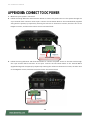
Installation & Operation:
This equipment must be grounded. The power cord for product should be connected to a socket-outlet with
earthing connection.
Cet équipement doit être mis à la terre. La fiche d'alimentation doit être connectée à une prise de terre
correctement câblée
Suitable for installation in Information Technology Rooms in accordance with Article 645 of the National
Electrical Code and NFPA 75.
Peut être installé dans des salles de matériel de traitement de l'information conformément à l'article 645 du
National Electrical Code et à la NFPA 75.
The machine can only be used in a restricted access location and must be installed by a skilled person.
Les matériels sont destinés à être installés dans des EMPLACEMENTS À ACCÈS RESTREINT.
This product is intended to be supplied by a Listed Power Adapter or DC power source, rated 12-24Vdc, 17.5-
8A minimum, Tma = 70°C, and the altitude of operation = 5000m.
Before turning on the device, ground the grounding cable of the equipment. Proper grounding (grounding) is
very important to protect the equipment against the harmful effects of external noise and to reduce the risk of
electrocution in the event of a lightning strike. To uninstall the equipment, disconnect the ground wire after
turning off the power. A ground wire is required and the part connecting the conductor must be greater than
4 mm2 or 10 AWG.
Avant d’allumer l’appareil, reliez le câble de mise à la terre de l’équipement à la terre.
Une bonne mise à la terre (connexion à la terre) est très importante pour protéger l’équipement contre les
effets néfastes du bruit externe et réduire les risques d’électrocution en cas de foudre.
Pour désinstaller l’équipement, débranchez le câble de mise à la terre après avoir éteint l’appareil.
Un câble de mise à la terre est requis et la zone reliant les sections du conducteur doit faire plus de 4 mm2
ou 10 AWG.

LEC-2290H User Manual
7
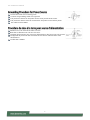
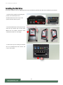
Loosen the screw of the earthing point.
Connect the grounding cable to the ground.
The protection device for the power source must provide 30 A current.
This protection device must be connected to the power source before power.
The cable hould 16 AWG
Desserrez la vis du terminal de mise à la terre.
Branchez le câble de mise à la terre à la terre.
L’appareil de protection pour la source d’alimentation doit fournir 30 A de courant.
Cet appareil de protection doit être branché à la source d’alimentation avant
l’alimentation.
Le câble doit 16 AWG

LEC-2290H User Manual
8
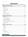
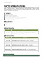
Key Features ..................................................................................................................................... 10
Package Content............................................................................................................................... 10
Ordering Information ....................................................................................................................... 10
Optional Accessories ........................................................................................................................ 10
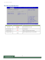
System Specifications ....................................................................................................................... 12
Front Panel ....................................................................................................................................... 14
Rear Panel ........................................................................................................................................ 15
Motherboard Information................................................................................................................ 16
Internal Jumpers and Connector ...................................................................................................... 19
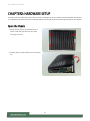
Open the Chassis .............................................................................................................................. 34
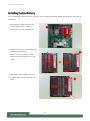
Installing System Memory ................................................................................................................ 35
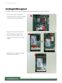
Installing mSATA Storage Card ......................................................................................................... 36
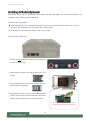
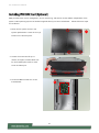
Installing 4G Module (Optional) ....................................................................................................... 37
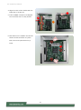
Install IPMI BMC Card (Optional) ..................................................................................................... 38
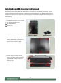
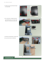
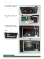
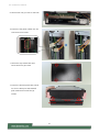
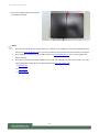
Installing Falcon-H8 AI Accelerator Card (Optional) ......................................................................... 40
Installing the Disk Drive .................................................................................................................... 45
Wall Mounting .................................................................................................................................. 46
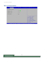
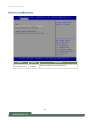
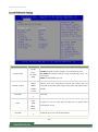
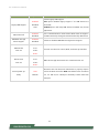
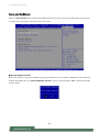
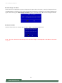
BIOS Setup ........................................................................................................................................ 48
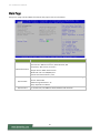
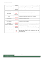
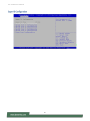
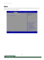
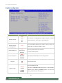
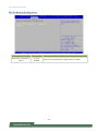
Main Page ......................................................................................................................................... 49
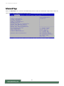
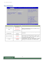
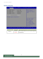
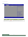
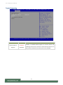
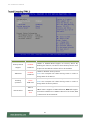
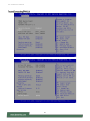
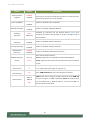
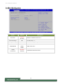
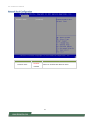
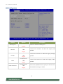
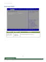
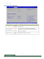
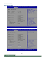
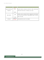
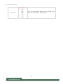
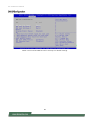
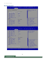
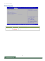
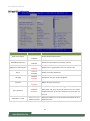
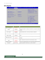
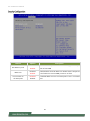
Advanced Page ................................................................................................................................. 50
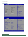
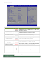
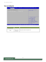
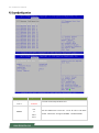
Chipset .............................................................................................................................................. 78
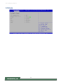
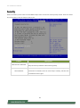
Security ............................................................................................................................................. 94
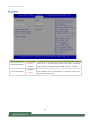
Boot Menu ........................................................................................................................................ 97
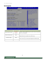
Save and Exit Menu .......................................................................................................................... 98
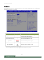
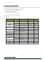
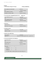
Command Line Configuration ........................................................................................................ 100


LEC-2290H User Manual
10
The LEC-2290H, when configured with Falcon-H8, makes available an easily deployable solution for engineers
looking to offload CPU loading for low-latency deep learning inference given that the Falcon-H8 (SKU A)
accommodates 6 Hailo-8™ AI processors, making it a modular, cost-effective Edge AI solution with high
processing capabilities and power efficiency.
Intel® CoreTM i7-9700TE
Falcon-H8 AI Accelerator Card Support
2x DDR4 2133/2400 SO-DIMM, Max 32GB
2x RJ45 GbE LAN, 4x PoE, 4x USB 3.0, 6x COM Ports, 8x DI & 8x DO
2x Removable HDD/SSD External Slot w/ RAID, 1x mSATA
Built-in TPM 2.0 & IPMI Support
Your package contains the following items:
1x LEC-2290H System Unit
4x Rubber Foot
SKU No.
Description
LEC-2290H
Intelligent Edge Computing Box PC with Intel® CoreTM i7-9700TE, 32GB System
Memory, mSATA128GB, 2.5” SSD/HDD storage, 240W AC/DC Adapter with
Falcon-H8 AI Accelerator Card Support
Model No.
Description
FALCON-H8A
IEK-AI0001A, Commercial Grade, Onboard 6x Hailo-8TM AI Processor
FALCON-H8B
IEK-AI0001B, Commercial Grade, Onboard 5x Hailo-8TM AI Processor
FALCON-H8C
IEK-AI0001C, Commercial Grade, Onboard 4x Hailo-8TM AI Processor
FALCON-H8D
IEK-AI0001D, Industrial Grade, Onboard 6x Hailo-8TM AI Processor
FALCON-H8E
IEK-AI0001E, Industrial Grade, Onboard 5x Hailo-8TM AI Processor
FALCON-H8F
IEK-AI0001F, Industrial Grade, Onboard 4x Hailo-8TM AI Processor
IAC-AST2500I
IPMI BMC Card
0TAW000234000
EG25GGB-MiniPCIe-S Quectel IoT/M2M-optimized LTE Cat 4
0TAW000165000
WPEQ-261ACN(BT) Sparklan WI-FI Card 2T2R Wi-Fi+Bluetooth 4.1 Combo
090W000791100
Extending Bracket for half-size mini-card in full-size miniPCIe

LEC-2290H User Manual
11
0TAW000222000
EM7455 Sierra LTE M.2 Card (Americas and EMEA), CAT 6
0TAW000147000
EM7430 Sierra LTE M.2 Card (Asia Pacific), CAT 6
0TAW000223000
EM7511 Sierra LTE M.2 Card (AT&T for the FirstNet), CAT 12
PSF7184-001
4G Module PGN-300 LTE KIT
PSF7877-001
4G Module PGN-600 LTE KIT
098W000004000
Wallmount Kit (with screws)
098W000006000
Rackmount Kit (with screws)

LEC-2290H User Manual
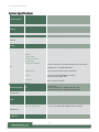
12
Processor System
CPU
Intel® Core™ i7-9700TE (Codenamed Coffee Lake S)
Frequency
Up to 1.8GHz
Core Number
8 Cores
Chipset
C246
Fanless
No
Memory
Technology
DDR4 2133/2400 SO-DIMM
Max. Capacity
Up to 32GB
Socket
2x 260-pin SO-DIMM
Graphic
Graphic Processor
Intel® UHD Graphics 630
Audio
Codec
TSI 92HD73C HD code
Ethernet
Controller
6x Intel i210IT Ethernet controller
Speed
10/100/1000 Mbps
PoE
4x IEEE 802.3af / IEEE 802.3at (Total PoE Budget of 60W)
Storage
HDD/SSD
2x Removable HDD/SSD external slot with RAID
mSATA
1x mSATA
I/O
COM Port
6x D-sub 9 COM Ports, support RS232/422/485
Ethernet Port
6x RJ45 GbE Ethernet Ports
USB Port
4x USB 3.0 Type A Ports
Audio Interface
1x Mic-in, 1x Line-out
Remote Power Switch
1x 2-Pin Remote Power Switch
LED Indicators
Power/Storage/WWAN/WLAN, refer to Appendix A
Reset/Power ON Button
1x Reset Button,
1x Power ON button w/ LED (Red-Standby, Green-Operating)
Display Port
1x Display Port, max. 4096x2304@60Hz;
2x HDMI Ports, max. 4096x2304@24Hz
Digital Interface
1x Terminal Block Isolation;
8x DI (12V), 8x DO (Sink mode, 12V@100mA)
PoE Port
4x PoE Ports, supporting IEEE802.3af (15.5W),
Single Port supporting IEEE802.3at (25.5W),
Total PoE Power Budget: 60W
Power Input
1x 4-Pin Terminal Block (Pin define: -/+/+/-) for 9~30V DC Input
(Normal 12VDC & 24VDC)
Antenna
4x SMA-type Antenna Holes
Expansion Interface
PCIe
1x PCIe*16 Slot;
1x PCIe*4 Slot;
1x mini-PCIe Slot (PCIe + USB2.0) with Nano-SIM;
1x M.2 B-Key Slot (PCIe + USB3.0) with Nano-SIM
Miscellaneous
Watchdog Timer
1~255 Level Time Interval System Reset, Software Programmable
TPM
Yes
Power
Connectors
1x 4-pin terminal block
Input
DC 9~30V (-/+/+/-)
Power Consumption (Idle)
29.5W@ +12VDC-IN
Power Consumption (Full Load)
121.6W@ +12VDC-IN
Environment
Operating Temperature
0°C~40°C (w/ Falcon-H8 & Adapter & Fans installed);
0°C~70°C (w/o Falcon-H8 & Adapter & Fans installed)
Storage Temperature
-40°C~70°C
Relative Humidity
10%~90% RH (non-condensing)
Vibration
IEC 60068-2-64, 0.5Grms, random 5~500Hz, 40mins/axis
Mechanical
Dimension (WxHxD)
275 x 225 x 115mm (without mounting)
Weight
6.2kg

LEC-2290H User Manual
13
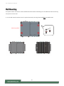
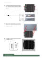
Mounting
Wallmount, Rackmount
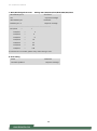
OS Support
Microsoft Windows
Windows 10 IoT 64bits Series
Linux
Linux Kernel 3.12 / Ubuntu 18.10 64bit above / CentOS 7 above /
Fedora30 64bit above

LEC-2290H User Manual
14
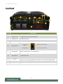
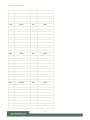
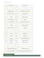
No.
Description
F1
Serial Port
3x DB9 Male Connector for RS232/422/485
F2
Ethernet Port
2x RJ45 GbE port with LED indicators
F3
USB 3.0 Port
4x USB 3.0 Type A
F4
Audio Jack
3.5mm Line-out and Mic-in Jack
F5
Remote Switch
1x 2-pin remote power switch
F6
LED Indicator
F7
Power Button
Power On/Off button with LED Indicator
F8
Reset Button
For software reset
F9
PoE Port
4x PoE Port with LED indicators supporting IEEE802.3af (15.5W),
Single port supporting IEEE802.3at (25.5W), Total PoE Power Budget: 60W
F10
DC Input
1x 4-pin terminal block (pin define: -/+/+/-) for 12V DC input (max. 200W)
F11
Storage Bay
2x HDD/SSD Disk Bays (9.5mm height each max.)
HDD/SSD1
HDD/SSD2
PoE1
F5
F9
F2
F1
F4
F3
PoE2
PoE3
PoE4
F10
Storage Status
System Power
Status
WLAN Connection Status
WWAN Connection Status
F11
F6
F8
F7

LEC-2290H User Manual
15
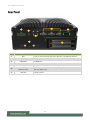
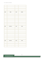
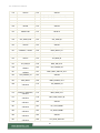
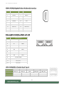
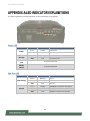
No.
Description
R1
DIO
1x 20-pin terminal block 8 DI (12V) & 8 DO (12V,100mA) Isolation
R2
Display Port
1x Display Port
R3
HDMI Port
2x HDMI Port
R4
Serial Port
3x DB9 Male Connector for RS232/422/485
R5
DC Input
1x 4-pin terminal block for DC 9~36V system power source
R6
Module Slot
(Antenna Port)
Removable PGN Module Slot supporting Dual SIM and 2x Antenna
Hole with dust cover
R7
PCIE Slot
1x PCIe *16 Slot
R1
R2
R3
R4
R5
R6
R7

LEC-2290H User Manual
16
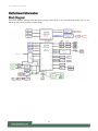
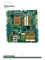
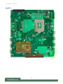
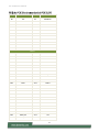
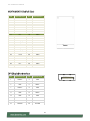
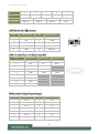
The block diagram indicates how data flows among components on the motherboard. Please refer to the
following figure for this system’s layout design.

LEC-2290H User Manual
17
Storage
Expansion
DDR4
DDR4
CPU
M.2
DIMM1
DIMM2
MSATA1
MPCIE1
JNGFF1

LEC-2290H User Manual
18
IPMI
BMC
Card
PCIe

LEC-2290H User Manual
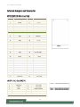
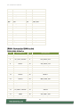
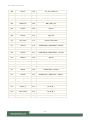
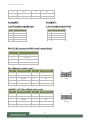
19
PIN
DESCRIPTION
PIN
DESCRIPTION
1
WAKE#
2
+3.3V
3
RSVD
4
GND
5
RSVD
6
+1.5V
7
CLKREQ#
8
UIM_PWR
9
GND
10
UIM_DATA
11
REFCLK-
12
UIM_CLK
13
REFCLK+
14
UIM_RESET
15
GND
16
UIM_VPP
KEY B
17
RSVD
18
GND
19
RSVD
20
W_DISABLE#
21
GND
22
PERST#
23
PERn0
24
+3.3V
25
PERp0
26
GND
27
GND
28
+1.5V
29
GND
30
SMB_CLK
31
PETn0
32
SMB_DATA
33
PETp0
34
GND
35
GND
36
USB_D+
37
GND
38
USB_D-
39
+3.3V
40
GND
41
+3.3V
42
LED_WWAN#
43
GND
44
LED_WLAN#
45
RSVD
46
LED_WPAN#
47
RSVD
48
+1.5V
49
RSVD
50
GND
51
RSVD
52
+3.3V
57
GND
56
NC
59
ANTCTL0
58
NC
61
ANTCTL1
60
COEX3
63
ANTCTL2
62
COEX2
65
ANTCTL3
64
COEX1
67
PEDET
66
SIM_DET
69
PEDET/CONFIG1
68
SUSCLK
71
GND
70
3V3_AUX
73
GND
72
3V3_AUX
75
CONFIG2
74
3V3_AUX
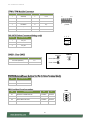
PIN
DESCRIPTION
PIN
DESCRIPTION
1
CONFIG3
2
3V3_AUX
3
GND
4
3V3_AUX
5
GND
6
CARD PWROFF
7
USB D+
8
W_DIS
9
USB D-
10
DAS/DSS#
11
GND
KEY B
MPCIE

LEC-2290H User Manual
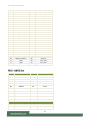
20
PIN
DESCRIPTION
PIN
DESCRIPTION
B1
12V
A1
PRSNT1#
B2
12V
A2
12V
B3
12V
A3
12V
B4
GND
A4
GND
B5
SMCLK
A5
JTAG2
B6
SMDAT
A6
JTAG3
B7
GND
A7
JTAG4
B8
3.3V
A8
JTAG5
B9
JTAG1
A9
3.3V
B10
3.3VAUX
A10
3.3V
B11
WAKE#
A11
PERST#
KEY B
B12
RSVD
A12
GND
B13
GND
A13
REFCLKA+
21
CONFIG0
20
AUDIO_0
23
NC
22
AUDIO_1
25
NC
24
AUDIO_2
27
GND
26
AUDIO_3
29
PERn1/USB3RX-
28
UIM_RFU
31
PERp1/USB3RX+
30
UIM_RESET
33
GND
32
UIM_CLK
35
PETn1/USB3TX-
24
UIM_DATA
37
PETp1/USB3TX+
36
UIM_PWR
39
GND
38
DEVSLP
41
PETn0/SATA_B+
40
GNSS0
43
PETp0/SATA_B-
42
GNSS1
45
GND
44
GNSS2
47
PERn0/SATA_A-
46
GNSS3
49
PERp0/SATA_A+
48
GNSS4
51
GND
50
PRESET#
53
REFCLK-
52
CLKREQ#
55
REFCLK+
54
WALE#
57
GND
56
NC
59
ANTCTL0
58
NC
61
ANTCTL1
60
COEX3
63
ANTCTL2
62
COEX2
65
ANTCTL3
64
COEX1
67
PEDET
66
SIM_DET
69
PEDET/CONFIG1
68
SUSCLK
71
GND
70
3V3_AUX
73
GND
72
3V3_AUX
75
CONFIG2
74
3V3_AUX
La page charge ...
La page charge ...
La page charge ...
La page charge ...
La page charge ...
La page charge ...
La page charge ...
La page charge ...
La page charge ...
La page charge ...
La page charge ...
La page charge ...
La page charge ...
La page charge ...
La page charge ...
La page charge ...
La page charge ...
La page charge ...
La page charge ...
La page charge ...
La page charge ...
La page charge ...
La page charge ...
La page charge ...
La page charge ...
La page charge ...
La page charge ...
La page charge ...
La page charge ...
La page charge ...
La page charge ...
La page charge ...
La page charge ...
La page charge ...
La page charge ...
La page charge ...
La page charge ...
La page charge ...
La page charge ...
La page charge ...
La page charge ...
La page charge ...
La page charge ...
La page charge ...
La page charge ...
La page charge ...
La page charge ...
La page charge ...
La page charge ...
La page charge ...
La page charge ...
La page charge ...
La page charge ...
La page charge ...
La page charge ...
La page charge ...
La page charge ...
La page charge ...
La page charge ...
La page charge ...
La page charge ...
La page charge ...
La page charge ...
La page charge ...
La page charge ...
La page charge ...
La page charge ...
La page charge ...
La page charge ...
La page charge ...
La page charge ...
La page charge ...
La page charge ...
La page charge ...
La page charge ...
La page charge ...
La page charge ...
La page charge ...
La page charge ...
La page charge ...
La page charge ...
La page charge ...
La page charge ...
La page charge ...
La page charge ...
La page charge ...
La page charge ...
-
 1
1
-
 2
2
-
 3
3
-
 4
4
-
 5
5
-
 6
6
-
 7
7
-
 8
8
-
 9
9
-
 10
10
-
 11
11
-
 12
12
-
 13
13
-
 14
14
-
 15
15
-
 16
16
-
 17
17
-
 18
18
-
 19
19
-
 20
20
-
 21
21
-
 22
22
-
 23
23
-
 24
24
-
 25
25
-
 26
26
-
 27
27
-
 28
28
-
 29
29
-
 30
30
-
 31
31
-
 32
32
-
 33
33
-
 34
34
-
 35
35
-
 36
36
-
 37
37
-
 38
38
-
 39
39
-
 40
40
-
 41
41
-
 42
42
-
 43
43
-
 44
44
-
 45
45
-
 46
46
-
 47
47
-
 48
48
-
 49
49
-
 50
50
-
 51
51
-
 52
52
-
 53
53
-
 54
54
-
 55
55
-
 56
56
-
 57
57
-
 58
58
-
 59
59
-
 60
60
-
 61
61
-
 62
62
-
 63
63
-
 64
64
-
 65
65
-
 66
66
-
 67
67
-
 68
68
-
 69
69
-
 70
70
-
 71
71
-
 72
72
-
 73
73
-
 74
74
-
 75
75
-
 76
76
-
 77
77
-
 78
78
-
 79
79
-
 80
80
-
 81
81
-
 82
82
-
 83
83
-
 84
84
-
 85
85
-
 86
86
-
 87
87
-
 88
88
-
 89
89
-
 90
90
-
 91
91
-
 92
92
-
 93
93
-
 94
94
-
 95
95
-
 96
96
-
 97
97
-
 98
98
-
 99
99
-
 100
100
-
 101
101
-
 102
102
-
 103
103
-
 104
104
-
 105
105
-
 106
106
-
 107
107


dans d''autres langues
- English: Lanner LEC-2290H User manual
Documents connexes
-
Lanner HAN-8360B Manuel utilisateur
-
-
-
-
-
-
-
-
Autres documents
-
ViziT EXIT 300 Mode d'emploi
-
Skov Loading system Technical User Guide
-
 v7world IFP6502-V7PRO Interactive Flat Panel Mode d'emploi
-
VESTEL OPS150-71 Manuel utilisateur
-
Fortin 94791 Guide d'installation
-
Adlink MECS-7211 Le manuel du propriétaire
-
Mitsubishi Electric MI2012-W Manuel utilisateur
-
Advantech EPC-U2117 Manuel utilisateur
-
Asus ROG MAXIMUS XII EXTREME Manuel utilisateur
-
 Hailo HFO 3697-10 Mode d'emploi

