Lanner NCA-6530 Manuel utilisateur
- Catégorie
- Les serveurs
- Taper
- Manuel utilisateur

NCA-6530
User Manual
Version: 1.0
Date of Release:2023-06-14
Network Appliance Platform

NCA-6530 User Manual
2
This manual describes the overview of the various functionalities of this product, and the information you
need to get it ready for operation. It is intended for those who are:
- responsible for installing, administering and troubleshooting this system or Information Technology
professionals.
- assumed to be qualified in the servicing of computer equipment, such as professional system
integrators, or service personnel and technicians.
The latest version of this document can be found on Lanner’s official website, available either through the
product page or through the Lanner Download Center page with a login account and password.
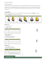
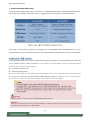
The icons are used in the manual to serve as an indication of interest topics or important messages.
Icon
Usage
This mark indicates that there is something you should pay special
attention to while using the product.
This mark indicates that there is a caution or warning and it is
something that could damage your property or product.
To obtain additional documentation resources and software updates for your system, please visit the
Lanner Download Center. As certain categories of documents are only available to users who are logged
in, please be registered for a Lanner Account at http://www.lannerinc.com/ to access published documents
and downloadable resources.
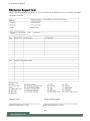
In addition to contacting your distributor or sales representative, you could submit a request at our Lanner
Technical Support and fill in a support ticket to our technical support department.
Your feedback is valuable to us, as it will help us continue to provide you with more accurate and relevant
documentation. To provide any feedback, comments or to report an error, please email
[email protected]m. Thank you for your time.
This document is copyrighted © 2023 by Lanner Electronics Inc. All rights are reserved. The original
manufacturer reserves the right to make improvements to the products described in this manual at any
time without notice. No part of this manual may be reproduced, copied, translated or transmitted in any
form or by any means without the prior written permission of the original manufacturer. Information
provided in this manual is intended to be accurate and reliable. However, the original manufacturer
assumes no responsibility for its use, nor for any infringements upon the rights of third parties that may
result from such use.
Note or Information
Warning or Important

NCA-6530 User Manual
3
Taiwan Corporate Headquarters
Lanner Electronics Inc.
7F, No.173, Sec.2, Datong Rd.
Xizhi District, New Taipei City 22184,
Taiwan
立端科技股份有限公司
221 新北市汐止區
大同路二段 173 號7樓
T: +886-2-8692-6060
F: +886-2-8692-6101
E: contact@lannerinc.com
China
Beijing L&S Lancom Platform Tech. Co., Ltd.
Guodong LOFT 9 Layer No. 9 Huinan Road,
Huilongguan Town, Changping District, Beijing
102208 China
T: +86 010-82795600
F: +86 010-62963250
E: service@ls-china.com.cn
USA
Lanner Electronics Inc.
47790 Westinghouse Drive
Fremont, CA 94539
T: +1-855-852-6637
F: +1-510-979-0689
E: sales_us@lannerinc.com
Canada
Lanner Electronics Canada Ltd
3160A Orlando Drive
Mississauga, ON
L4V 1R5 Canada
T: +1 877-813-2132
F: +1 905-362-2369
E: sales_ca@lannerinc.com
Europe
Lanner Europe B.V.
Wilhelmina van Pruisenweg 104
2595 AN The Hague
The Netherlands
T: +31 70 701 3256
E: sales_eu@lannerinc.com

NCA-6530 User Manual
4
Intel® and Intel® Celeron® are trademarks of Intel Corporation or its subsidiaries in the U.S. and/or other countries.
Microsoft Windows and MS-DOS are registered trademarks of Microsoft Corp.
All other product names or trademarks are properties of their respective owners.
This equipment has been tested and found to comply with the limits for a Class A digital device, pursuant to Part 15 of
FCC Rules. These limits are designed to provide reasonable protection against harmful interference in a residential
installation. This equipment generates, uses and can radiate radio frequency energy and, if not installed and used in
accordance with the instruction, may cause harmful interference to radio communications. However, there is no
guarantee that interference will not occur in a particular installation. If this equipment does cause harmful interference
to radio or television reception, which can be determined by turning the equipment off and on, the user is encouraged
to try to correct the interference by one or more of the following measures:
Reorient or relocate the receiving antenna.
Increase the separation between the equipment and receiver.
Connect the equipment into an outlet on a circuit different from that to which the receiver is connected.
Consult the dealer or an experienced radio/TV technician for help.
Any changes or modifications not expressly approved by the party responsible for compliance could void the
user's authority to operate this equipment.
This transmitter must not be co-located or operating in conjunction with any other antenna or transmitter.
Note
1. An unshielded-type power cord is required in order to meet FCC emission limits and also to prevent interference
to the nearby radio and television reception. It is essential that only the supplied power cord be used.
2. Use only shielded cables to connect I/O devices to this equipment.
3. Changes or modifications not expressly approved by the party responsible for compliance could void the user’s
authority to operate the equipment.
Important
1. Operations in the 5.15-5.25GHz band are restricted to indoor usage only.
2. This device meets all the other requirements specified in Part 15E, Section 15.407 of the FCC Rules.

NCA-6530 User Manual
5
Follow these guidelines to ensure general safety:
Keep the chassis area clear and dust-free during and after installation.
Do not wear loose clothing or jewelry that could get caught in the chassis. Fasten your tie or scarf and roll up your
sleeves.
Wear safety glasses if you are working under any conditions that might be hazardous to your eyes.
Do not perform any action that creates a potential hazard to people or makes the equipment unsafe.
Disconnect all power by turning off the power and unplugging the power cord before installing or removing a
chassis or working near power supplies
Do not work alone if potentially hazardous conditions exist.
Never assume that power is disconnected from a circuit; always check the circuit.
Suivez ces consignes pour assurer la sécurité générale :
Laissez la zone du châssis propre et sans poussière pendant et après l’installation.
Ne portez pas de vêtements amples ou de bijoux qui pourraient être pris dans le châssis. Attachez votre cravate ou
écharpe et remontez vos manches.
Portez des lunettes de sécurité pour protéger vos yeux.
N’effectuez aucune action qui pourrait créer un danger pour d’autres ou rendre l’équipement dangereux.
Coupez complètement l’alimentation en éteignant l’alimentation et en débranchant le cordon d’alimentation avant
d’installer ou de retirer un châssis ou de travailler à proximité de sources d’alimentation.
Ne travaillez pas seul si des conditions dangereuses sont présentes.
Ne considérez jamais que l’alimentation est coupée d’un circuit, vérifiez toujours le circuit. Cet appareil génère,
utilise et émet une énergie radiofréquence et, s’il n’est pas installé et utilisé conformément aux instructions des
fournisseurs de composants sans fil, il risque de provoquer des interférences dans les communications radio.
There is risk of explosion if the battery is replaced by an incorrect type.
Dispose of used batteries according to the instructions.
Installation should be conducted only by a trained electrician or only by an electrically trained person who knows
all installation procedures and device specifications which are to be applied.
Do not carry the handle of power supplies when moving to another place.
Please conform to your local laws and regulations regarding safe disposal of lithium battery.
Disposal of a battery into fire or a hot oven, or mechanically crushing or cutting of a battery can result in an
explosion.
Leaving a battery in an extremely high temperature environment can result in an explosion or the leakage of
flammable liquid or gas.
A battery subjected to extremely low air pressure may result in an explosion or the leakage of flammable liquid or
gas.
Risque d’explosion si la pile est remplacée par une autre d’un mauvais type.
Jetez les piles usagées conformément aux instructions.
L’installation doit être effectuée par un électricien formé ou une personne formée à l’électricité connaissant toutes
les spécifications d’installation et d’appareil du produit.
Ne transportez pas l’unité en la tenant par le câble d’alimentation lorsque vous déplacez l’appareil.
Electrical equipment generates heat. Ambient air temperature may not be adequate to cool equipment to
acceptable operating temperatures without adequate circulation. Be sure that the room in which you choose to
operate your system has adequate air circulation.
Ensure that the chassis cover is secure. The chassis design allows cooling air to circulate effectively. An open
chassis permits air leaks, which may interrupt and redirect the flow of cooling air from internal components.
Electrostatic discharge (ESD) can damage equipment and impair electrical circuitry. ESD damage occurs when
electronic components are improperly handled and can result in complete or intermittent failures. Be sure to follow
ESD-prevention procedures when removing and replacing components to avoid these problems.
Wear an ESD-preventive wrist strap, ensuring that it makes good skin contact. If no wrist strap is available, ground

NCA-6530 User Manual
6
yourself by touching the metal part of the chassis.
Periodically check the resistance value of the antistatic strap, which should be between 1 and 10 megohms
(Mohms).
L’équipement électrique génère de la chaleur. La température ambiante peut ne pas être adéquate pour refroidir
l’équipement à une température de fonctionnement acceptable sans circulation adaptée. Vérifiez que votre site
propose une circulation d’air adéquate.
Vérifiez que le couvercle du châssis est bien fixé. La conception du châssis permet à l’air de refroidissement de bien
circuler. Un châssis ouvert laisse l’air s’échapper, ce qui peut interrompre et rediriger le flux d’air frais destiné aux
composants internes.
Les décharges électrostatiques (ESD) peuvent endommager l’équipement et gêner les circuits électriques. Des
dégâts d’ESD surviennent lorsque des composants électroniques sont mal manipulés et peuvent causer des pannes
totales ou intermittentes. Suivez les procédures de prévention d’ESD lors du retrait et du remplacement de
composants.
Portez un bracelet anti-ESD et veillez à ce qu’il soit bien au contact de la peau. Si aucun bracelet n’est disponible,
reliez votre corps à la terre en touchant la partie métallique du châssis.
Vérifiez régulièrement la valeur de résistance du bracelet antistatique, qui doit être comprise entre 1 et 10
mégohms (Mohms).
Mounting Installation Precautions
The following should be put into consideration for rack-mount or similar mounting installations:
Do not install and/or operate this unit in any place that flammable objects are stored or used in.
The installation of this product must be performed by trained specialists; otherwise, a non-specialist might create
the risk of the system’s falling to the ground or other damages.
Lanner Electronics Inc. shall not be held liable for any losses resulting from insufficient strength for supporting the
system or use of inappropriate installation components.
Elevated Operating Ambient - If installed in a closed or multi-unit rack assembly, the operating ambient
temperature of the rack environment may be greater than room ambient. Therefore, consideration should be given
to installing the equipment in an environment compatible with the maximum ambient temperature (Tma) specified
by the manufacturer.
Reduced Air Flow - Installation of the equipment in a rack should be such that the amount of airflow required for
safe operation of the equipment is not compromised.
Mechanical Loading - Mounting of the equipment in the rack should be such that a hazardous condition is not
achieved due to uneven mechanical loading.
Circuit Overloading - Consideration should be given to the connection of the equipment to the supply circuit and
the effect that overloading of the circuits might have on overcurrent protection and supply wiring. Appropriate
consideration of equipment nameplate ratings should be used when addressing this concern.
Reliable Grounding - Reliable grounding of rack mounted equipment should be maintained. Particular attention
should be given to supply connections other than direct connections to the branch circuit (e.g. use of power strips).
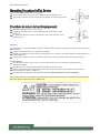
Instruction for the installation of the conductor to building earth by a skilled person.
Before turning on the device, ground the grounding cable of the equipment. Proper grounding (grounding) is very
important to protect the equipment against the harmful effects of external noise and to reduce the risk of
electrocution in the event of a lightning strike. To uninstall the equipment, disconnect the ground wire after turning
off the power. A ground wire (green-and-yellow) is required and the part connecting the conductor must be greater
than 6 mm2 or 8AWG.
Avant d’allumer l’appareil, reliez le câble de mise à la terre de l’équipement à la terre.
Une bonne mise à la terre (connexion à la terre) est très importante pour protéger l’équipement contre les effets
néfastes du bruit externe et réduire les risques d’électrocution en cas de foudre.
Pour désinstaller l’équipement, débranchez le câble de mise à la terre après avoir éteint l’appareil.
Un câble de mise à la terre est requis et la zone reliant les sections du conducteur doit faire plus de 6 mm2 ou 8
AWG.

NCA-6530 User Manual
7
Connect the grounding cable to the ground.
The protection device for the DC power source must provide 40A current.
This protection device must be connected to the power source before DC power.
Branchez le câble de mise à la terre à la terre.
L’appareil de protection pour la source d’alimentation CC doit fournir 40A
de courant.
Cet appareil de protection doit être branché à la source d’alimentation avant
l’alimentation CC.
Warning
This equipment must be grounded. The power cord for product should be connected to a socket-outlet with earthing
connection.
Product shall be used with Class 1 laser device modules.
Suitable for installation in Information Technology Rooms in accordance with Article 645 of the National Electrical
Code and NFPA 75.
The machine can only be used in a restricted access location and be installed and serviced by skilled person.
Avertissement
Cet équipement doit être mis à la terre. La fiche d'alimentation doit être connectée à une prise de terre
correctement câblée
Le produit doit être utilisé avec des modules de dispositifs laser de classe 1.
Peut être installé dans des salles de matériel de traitement de l'information conformément à l'article 645 du
National Electrical Code et à la NFPA 75.
Les matériels sont destinés à être installés dans des EMPLACEMENTS À ACCÈS RESTREINT.
For DC input, this unit is intended to be supplied by an UL listed power source, rated 48V to 60Vdc, 40A min,
60A max, and an altitude operation 5000m min.

NCA-6530 User Manual
8
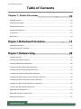
Table of Contents
Chapter 1: Product Overview
Package Content ......................................................................................................................... 10
Ordering Information ................................................................................................................. 10
Optional Accessories .................................................................................................................. 10
System Specifications ................................................................................................................. 11
Front Panel ................................................................................................................................. 12
Rear Panel ................................................................................................................................... 14
Motherboard Layout .................................................................................................................. 16
Internal Jumper & Connectors ................................................................................................... 17
Installing the CPU ....................................................................................................................... 29
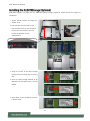
Installing the System Memory .................................................................................................... 36
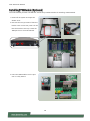
Installing TPM Module (Optional) .............................................................................................. 38
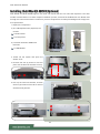
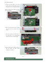
Installing the M.2 SSD Storage (Optional) .................................................................................. 39
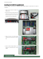
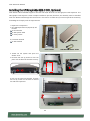
Installing the M.2 SATA Storage (Optional) ................................................................................ 41
Installing the LAN Card (A & B SKU, Optional) ........................................................................... 42
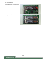
Installing the GPU Graphic Card (C & D SKU, Optional) ............................................................. 44
Installing the Disk Drive(s) (A & C SKU, Optional) ...................................................................... 47
Installing the Disk Drive(s) (B & D SKU, Optional) ...................................................................... 49
Installing the NIC Modules (Optional) ........................................................................................ 51
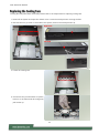
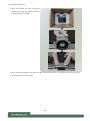
Replacing the Cooling Fans ......................................................................................................... 53
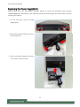
Replacing the Power Supply Units ............................................................................................. 55
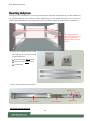
Mounting the System ................................................................................................................. 56

NCA-6530 User Manual
9
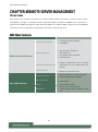
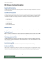
BMC Main Features .................................................................................................................... 61
BMC Firmware Functional Description ...................................................................................... 62
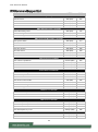
IPMI Commands Support List ..................................................................................................... 64
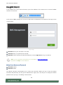
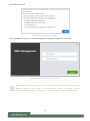
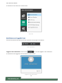
Using BMC Web UI ..................................................................................................................... 66
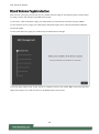
Web UI Layout Introduction ....................................................................................................... 69
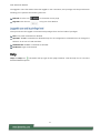
Help............................................................................................................................................. 71
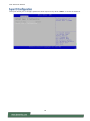
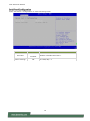
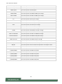
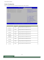
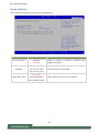
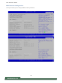
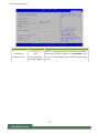
Main Page ................................................................................................................................... 73
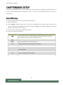
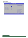
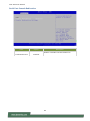
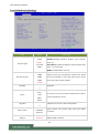
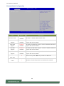
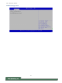
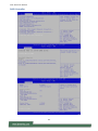
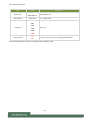
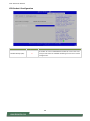
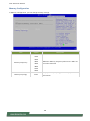
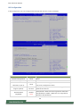
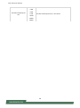
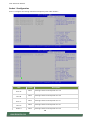
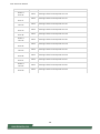
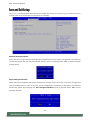
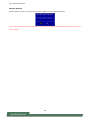
Platform Setup ............................................................................................................................ 94
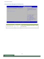
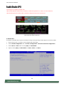
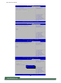
Server Mgmt Setup ................................................................................................................... 113
Security Setup ........................................................................................................................... 119
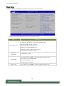
Boot Setup ................................................................................................................................ 122
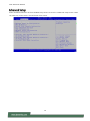
Save and Exit Setup .................................................................................................................. 123
Warranty Policy ........................................................................................................................ 136

NCA-6530 User Manual
10
CHAPTER 1: PRODUCT OVERVIEW
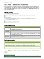
Thank you for choosing NCA-6530. The NCA-6530, a high-performance 2U rackmount network appliance,
is powered by Intel® Xeon® Processor Scalable Family (Codenamed Sapphire Rapids-SP) and supports up
to 8x NIC slots, Max. 1536GB system memory, 6x hot-swappable fans, 1600W/2000W redundant PSUs,
Intel® QAT and optional PCIE.
Your package contains the following items:
1x NCA-6530 Network Security Platform
2x Power Cables, 1x RJ45 Console Cable, 1x RJ45 LAN Cable, 1x RJ45 Cross-over LAN Cable
2x CPU Heatsink
2x Processor Carrier (E1A for XCC CPU Series), 2x Processor Carrier (E1B for MCC CPU Series)
10x 2.5” HDD Screws (SKU A/C only)
12x U.2 NvME Screw Sets (SKU B/D only)
2x Short Ear Rack Mount Kit with Screws
SKU No.
Description
NCA-6530A
Up To 2x Sapphire Rapids-SP (350W), 2x GbE RJ45 MGMT, AST2600 MGMT with 1600W
1+1 Redundancy PSU, 2x 2.5’’HDD
NCA-6530B
Up To 2x Sapphire Rapids-SP (350W), 2x GbE RJ45 MGMT, AST2600 MGMT with 1600W
1+1 Redundancy PSU, 12x 2.5’’ NVME HDD
NCA-6530C
Up To 2x Sapphire Rapids-SP (185W), 2x GbE RJ45 MGMT, AST2600 MGMT with 2000W
1+1 Redundancy PSU, 2x 2.5’’HDD
NCA-6530D
Up To 2x Sapphire Rapids-SP (185W), 2x GbE RJ45 MGMT, AST2600 MGMT with 2000W
1+1 Redundancy PSU, 12x 2.5’’ NVME HDD
Model
Description
Riser Card Kit-1 RC-65301A
Riser card kit for rear FH/HL dual-slot PCIe bracket with fan
Riser Card Kit-2 RC-65301A
Riser card kit for rear FH/HL dual-slot PCIe bracket without fan
Riser Card Kit-3 RC-65301A
Riser card kit for rear FH/HL dual-slot PCIe bracket with fan
Riser Card Kit-4 RC-65301A
Riser card kit for rear FH/HL dual-slot PCIe bracket without fan
FAN KIT 60 NCA-6530A
Swappable Fan kit, suitable for NCA-6530A/B/C/D
Note: If any component is missing or damaged, please contact your dealer immediately for
assistance.

NCA-6530 User Manual
11
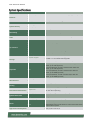
Form Factor
2U 19“ Rackmount
Platform
Processor Options
Intel® Xeon® Processor Scalable Family (Sapphire Rapids-SP)
CPU Socket
2x LGA4677
Chipset
Intel® C741
Security Acceleration
Intel® QuickAssist Technology
BIOS
AMI SPI Flash BIOS
System Memory
Technology
DDR5 4800 MHz R-DIMM
Max. Capacity
1536GB
Socket
24x 288-pin DIMM
Networking
Ethernet Ports
2x GbE RJ45 Intel® i350-AM2
Bypass
Depends on NIC Module Specifications
NIC Module Slot
8x NIC Module Slots
LOM
IO Interface
1x RJ45 LOM Port via BMC for remote management
OPMA Slot
IPMI Onboard
I/O Interface
Reset Button
1x Reset Button
LED Indicators
Power/Status/Storage LED Indicators
Power Button
1x ATX Power Switch
Console Port
1x RJ45 Console Port
USB Port
2x USB 3.0 Ports
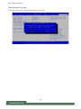
LCD Module
Yes, 2x20 Character LCM w/4 x Keypads
Display Port
1x VGA Port (Internal Pin Header)
Power Input
AC Power Inlet on PSU
Storage
HDD/SSD Support
SKU A&C : 2x 2.5” HDD/SSD Swappable
SKU B&D : 12x U.2 NVMe SSD Swappable
Onboard Slots
2x M.2 2280 M-Key NVME; 1x M.2 2280 M-Key SATA
Expansion
PCIe
SKU A: N/A (Default); 2x PCIE x16 Gen5 FH/HL single-slot
bracket; up to 75W (Optional)
SKU B: N/A (Default); 2x PCIE x16 Gen5 FH/HL single-slot
bracket, up to 75W (Optional)
SKU C: N/A (Default); 2x PCIE x16 Gen5 FH/FL dual-slot
bracket, up to 300W (Optional)
SKU D: N/A (Default); 2x PCIE x16 Gen5 FH/FL dual-slot
bracket, up to 300W (Optional)
Miscellaneous
Watchdog
YES
Internal RTC with Li Battery
YES
TPM
TPM 2.0 (Optional)
Cooling
Processor
Passive CPU Heatsink
System
6x Individual Hot-swappable Cooling Smart Fans
Environmental Parameters
Temperature
0~40ºC Operating
-20~70ºC Non-Operating
Humidity (RH)
5~90% Operating; 5~95% Non-Operating
System Dimensions
(WxDxH)
438mm x 760mm x 88mm
Weight
21.2kg
Package Dimensions
(WxDxH), Weight
588mm x 926mm x 303mm, 31.2kg
Power
Type/Watts
1600W/2000W, 1+1 ATX Redundant PSUs
Input
AC 200~240V @50~60 Hz
Noted: Please input in high voltage to ensure the power supply
output sufficient power.
Approvals and Compliance
RoHS, CE/FCC Class A, UL

NCA-6530 User Manual
12
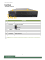
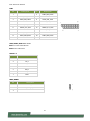
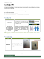
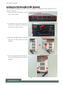
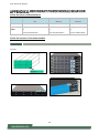
Note: Please refer to Appendix A: LED Indicator Explanations for descriptions of the LED Indicators.
No.
Description
F1
HDD/SSD Bays
2x 2.5” HDD/SSD Trays
F2
LCM
16x2 Character LCD, 4x Keypads
F3
Reset Button
1x Software Reset Button
F4
LED Indicators
F5
USB Port
2x USB 3.0 Ports
F6
LAN Port
2x GbE RJ45 Ports
F7
LOM Port
1x RJ45 LOM Port for Remote Management
F8
Console Port
1x RJ45 Console Port
F9
NCS2 Module
8x Standard NIC Module Slots
NCA-6530A / NCA-6530C
System Power
System Status
HDD Activity
F1
F2
F3
F4
F5
F6
F7
F8
F9

NCA-6530 User Manual
13
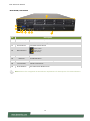
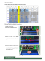
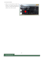
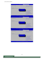
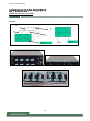
Note: Please refer to Appendix A: LED Indicator Explanations for descriptions of the LED Indicators.
No.
Description
F1
HDD/SSD Bays
12x U.2 NVMe SSD Trays
F2
LCM
16x2 Character LCD, 4x Keypads
F3
Reset Button
1x Software Reset Button
F4
LED Indicators
F5
USB Port
2x USB 3.0 Ports
F6
LAN Port
2x GbE RJ45 Ports
F7
LOM Port
1x RJ45 LOM Port for Remote Management
F8
Console Port
1x RJ45 Console Port
F9
NCS2 Module
8x Standard NIC Module Slots
NCA-6530B / NCA-6530D
System Power
System Status
HDD Activity
F1
F2
F3
F4
F5
F6
F7
F8
F9

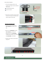
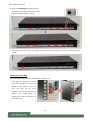
NCA-6530 User Manual
14
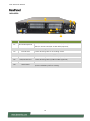
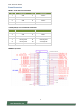
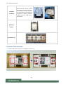
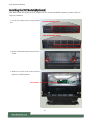
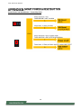
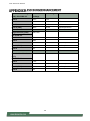
No.
Description
R1
Rear PCIe Expansion
SKU A/B: 2x PCIE x16 FH/HL at Rear Side (Optional);
SKU C/D: 2x PCIE x16 FH/FL at Rear Side (Optional);
R2
ESD Jack
1x Semi-Shearing hole for ESD screws
R3
Ground Hole
2x Semi-Shearing Hole for Grounding screws
R4
Power Supply
2x 1+1 Redundant Power Supply
R5
USB Port
1x Semi-Shearing Hole for USB Port (Optional)
R6
VGA/Console Port
1x Semi-Shearing Hole by DB9 or DB15 (Optional)
R7
Power Switch
1x Power Button
R8
Alarm Reset
1x Alarm Reset Button, an audible alarm will sound when the
system’s redundant power is missing.
NCA-6530
R4
R1
R2
R3
R4
R5
R6
R7
R8

NCA-6530 User Manual
15
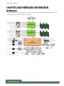
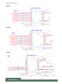
The block diagram indicates how data flows among components on the motherboard. Please refer to the
following figure for the motherboard layout design.

NCA-6530 User Manual
16
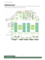
The motherboard layout shows the connectors and jumpers on the board. Refer to the following picture as
a reference of the pin assignments and the internal connectors.

NCA-6530 User Manual
17
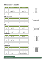
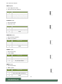
JUSB1: USB 2.0
Pin
Description
Pin
Description
1
+P5V_USB2
2
+P5V_USB2
3
USB20_L_N0
4
USB20_L_N1
5
USB20_L_P0
6
USB20_L_P1
7
USBGND1
8
USBGND1
9
USBGND1
10
USBGND1
PLD1: CPLD pin header
Pin
Description
Pin
Description
1
+P3V3_AUX
2
JTAG_PLD_TDO
3
JTAG_PLD_TDI
4
JTAG_PLD_TMS
5
GND
6
JTAG_PLD_TCK
JGP1
Pin
Description
Pin
Description
1
GPO_B_1
2
GPI_B_1
3
GPO_B_2
4
GPI_B_2
5
GPO_B_3
6
GPI_B_3
7
GPO_B_4
8
GPI_B_4
9
GND
10
GND
JESPI80PORT1
Pin
Description
Pin
Description
1
ESPI_CLK
2
ESPI_IO1
3
ESPI_RST#
4
ESPI_IO0
5
ESPI_CS#
6
+P3V3
7
ESPI_IO3
8
9
ESPI_IO2
10
GND
11
+P3V3_AUX
12
JBMCSPIROM2
Pin
Description
Pin
Description
1
BMC_SPI_HD1#
2
BMC_SPI_DEDI_IO2
3
BMC_SPI_DEDI_CS0
4
+P3V3_SPI_BMC_AUX
5
BMC_SPI_DEDI_MISO
6
BMC_SPI_DEDI_IO3
7
8
BMC_SPI_DEDI_CLK
9
GND
10
BMC_SPI_DEDI_MOSI

NCA-6530 User Manual
18
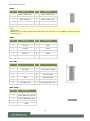
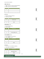
JCOM1
Pin
Description
Pin
Description
1
BMC_COM2_DCD#
2
BMC_COM2_DSR#
3
BMC_COM2_RX
4
BMC_COM2_RTS
5
BMC_COM2_TX
6
BMC_COM2_CTS#
7
BMC_COM2_DTR
8
BMC_COM2_RI#
9
IOGND2
10
JVGA1
Pin
Description
Pin
Description
1
DAC_RO
2
GND
3
DAC_GO
4
GND
5
DAC_BO
6
GND
7
HSYNC_O
8
9
VSYNC_O
10
GND
11
DDC_DATA
12
DDC_CLK
JSPI_TPM1
Pin
Description
Pin
Description
1
SPI_HD1#
2
SPI_CS1#
3
SPI_CS0#
4
+P3V3_SPI_PCH_AUX
5
SPI_MISO_TPM
6
HEADER_SPI_PCH_IO3
7
8
SPI_CLK_TPM
9
GND
10
SPI_MOSI_TPM
11
IRQ_TPM_SPI#_R
12
13
SPI_TPM_CS0#
14
RST_PLTRST_PLD_B_N
JBMC_SGPIO1
Pin
Description
1
SGPIO_DEBUG_PLD_CLK
2
SGPIO_DEBUG_PLD_DOUT
3
SGPIO_DEBUG_PLD_DIN
4
SGPIO_DEBUG_PLD_LD_N
5
GND
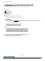
Note
The rear console (COM1) and the front LCM (LCM1) uses the same pin. Only one pin can be supported
for use at a time.

NCA-6530 User Manual
19
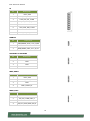
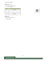
J8
Pin
Description
1
+P3V3_AUX
2
JTAG_ASD_TDO_CONN
3
JTAG_ASD_TDI_CONN
4
JTAG_ASD_NTRST_N_CONN
5
6
JTAG_ASD_TMS_CONN
7
GND
8
JTAG_ASD_TCK_CONN
JPMBUS1
Pin
Description
1
SMB_PMBUS_STBY_LVC3_R_SDA
2
GND
3
SMB_PMBUS_STBY_LVC3_R_SCL
JSATAPW1 & JSATAPW2
Pin
Description
1
+P12V
2
GND
3
GND
4
+P5V
JBMC_UART1
Pin
Description
1
+P3V3_AUX
2
BMC_UART5_RX
3
GND
4
BMC_UART5_TX
JRAID_CON1
Pin
Description
1
GND
2
PU_KEY_CONN_PIN2_R
3
GND
4
FM_PCH_SATA_RAID_KEY_R

NCA-6530 User Manual
20
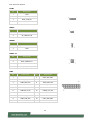
JLCM1
Pin
Description
1
GND
2
BMC_LCM_TX
3
BMC_LCM_RX
4
+P5V
JPWR1
Pin
Description
1
GND
2
FP_PWR_BTN_N
JOPEN1
Pin
Description
1
FP_CHASSIS_INTRUSION
2
GND
JFAN5~10
Pin
Description
1
GND
2
BMC_PWMOUT1
3
+P12V
4
BMC_FAN_TECH_IN3
USB2
Pin
Description
Pin
Description
1
2
USB3_P09_RXN
3
USB3_P09_RXP
4
GND
5
USB3_P09_TXN
6
USB3_P09_TXP
7
GND
8
USB20_P11_DN
9
USB20_P11_DP
10
11
USB20_P13_DP
12
USB20_P13_DN
13
GND
14
USB3_P08_TXP
15
USB3_P08_TXN
16
GND
17
USB3_P08_RXP
18
USB3_P08_RXN
19
20
La page charge ...
La page charge ...
La page charge ...
La page charge ...
La page charge ...
La page charge ...
La page charge ...
La page charge ...
La page charge ...
La page charge ...
La page charge ...
La page charge ...
La page charge ...
La page charge ...
La page charge ...
La page charge ...
La page charge ...
La page charge ...
La page charge ...
La page charge ...
La page charge ...
La page charge ...
La page charge ...
La page charge ...
La page charge ...
La page charge ...
La page charge ...
La page charge ...
La page charge ...
La page charge ...
La page charge ...
La page charge ...
La page charge ...
La page charge ...
La page charge ...
La page charge ...
La page charge ...
La page charge ...
La page charge ...
La page charge ...
La page charge ...
La page charge ...
La page charge ...
La page charge ...
La page charge ...
La page charge ...
La page charge ...
La page charge ...
La page charge ...
La page charge ...
La page charge ...
La page charge ...
La page charge ...
La page charge ...
La page charge ...
La page charge ...
La page charge ...
La page charge ...
La page charge ...
La page charge ...
La page charge ...
La page charge ...
La page charge ...
La page charge ...
La page charge ...
La page charge ...
La page charge ...
La page charge ...
La page charge ...
La page charge ...
La page charge ...
La page charge ...
La page charge ...
La page charge ...
La page charge ...
La page charge ...
La page charge ...
La page charge ...
La page charge ...
La page charge ...
La page charge ...
La page charge ...
La page charge ...
La page charge ...
La page charge ...
La page charge ...
La page charge ...
La page charge ...
La page charge ...
La page charge ...
La page charge ...
La page charge ...
La page charge ...
La page charge ...
La page charge ...
La page charge ...
La page charge ...
La page charge ...
La page charge ...
La page charge ...
La page charge ...
La page charge ...
La page charge ...
La page charge ...
La page charge ...
La page charge ...
La page charge ...
La page charge ...
La page charge ...
La page charge ...
La page charge ...
La page charge ...
La page charge ...
La page charge ...
La page charge ...
La page charge ...
La page charge ...
-
 1
1
-
 2
2
-
 3
3
-
 4
4
-
 5
5
-
 6
6
-
 7
7
-
 8
8
-
 9
9
-
 10
10
-
 11
11
-
 12
12
-
 13
13
-
 14
14
-
 15
15
-
 16
16
-
 17
17
-
 18
18
-
 19
19
-
 20
20
-
 21
21
-
 22
22
-
 23
23
-
 24
24
-
 25
25
-
 26
26
-
 27
27
-
 28
28
-
 29
29
-
 30
30
-
 31
31
-
 32
32
-
 33
33
-
 34
34
-
 35
35
-
 36
36
-
 37
37
-
 38
38
-
 39
39
-
 40
40
-
 41
41
-
 42
42
-
 43
43
-
 44
44
-
 45
45
-
 46
46
-
 47
47
-
 48
48
-
 49
49
-
 50
50
-
 51
51
-
 52
52
-
 53
53
-
 54
54
-
 55
55
-
 56
56
-
 57
57
-
 58
58
-
 59
59
-
 60
60
-
 61
61
-
 62
62
-
 63
63
-
 64
64
-
 65
65
-
 66
66
-
 67
67
-
 68
68
-
 69
69
-
 70
70
-
 71
71
-
 72
72
-
 73
73
-
 74
74
-
 75
75
-
 76
76
-
 77
77
-
 78
78
-
 79
79
-
 80
80
-
 81
81
-
 82
82
-
 83
83
-
 84
84
-
 85
85
-
 86
86
-
 87
87
-
 88
88
-
 89
89
-
 90
90
-
 91
91
-
 92
92
-
 93
93
-
 94
94
-
 95
95
-
 96
96
-
 97
97
-
 98
98
-
 99
99
-
 100
100
-
 101
101
-
 102
102
-
 103
103
-
 104
104
-
 105
105
-
 106
106
-
 107
107
-
 108
108
-
 109
109
-
 110
110
-
 111
111
-
 112
112
-
 113
113
-
 114
114
-
 115
115
-
 116
116
-
 117
117
-
 118
118
-
 119
119
-
 120
120
-
 121
121
-
 122
122
-
 123
123
-
 124
124
-
 125
125
-
 126
126
-
 127
127
-
 128
128
-
 129
129
-
 130
130
-
 131
131
-
 132
132
-
 133
133
-
 134
134
-
 135
135
-
 136
136
-
 137
137


Lanner NCA-6530 Manuel utilisateur
- Catégorie
- Les serveurs
- Taper
- Manuel utilisateur
dans d''autres langues
- English: Lanner NCA-6530 User manual
Documents connexes
-
Lanner HAN-8360B Manuel utilisateur
-
-
-
-
-
-
-
-
Autres documents
-
Dell S4112F 1.1 Mode d'emploi
-
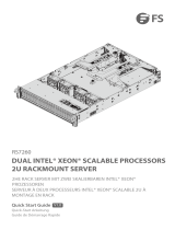 FS RS7260 Manuel utilisateur
-
Adlink MECS-7211 Le manuel du propriétaire
-
-
Sames Volurex electric part PARVEX Motorizing Manuel utilisateur
-
 KVM-TEC kvm-tec KT-6032L USBflex single fiber KVM Extender Guide d'installation
-
Oracle SPARC T7-2 Guide d'installation
-
 SEMES SSD-100 Smoke and Temperature Detection Manuel utilisateur
-
-
Pyramid TTEZEK Mode d'emploi


