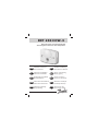
Danfoss RET230 HCW3 Guide d'installation
- Taper
- Guide d'installation

RET 230 HCW-3
GB
F
D
ES
DK
NL
GR
LT
PL
I
Installation Instructions
User Instructions
Instructions d’installation
Instructions d’utilisateur
Anweisungen für Installati
Benutzeranweisen
Instrucciones de instalación
Instrucciones del usuario
Instruktions vejledning
Brugervejleding
Electronic Heat / Cool thermostat with
auto-changeover based on water temperature
Installatie handleiding
Instructiesevoor Gebruik
Ïäçãßåò åãêáôÜóôáóçò
Ïäçãßåò ÷ñÞóçò
Instrukcja instalacji
Instrukcja Użytkownika
Montavimo instrukcijos
Informacija Vartotojui
Istruzioni per l’uso
Istruzioni per l’utente

2
Index
INDEX
Installation Instructions 3-9
User Instructions 10
Instructions d’installation 11-17
Instructions d’utilisateur 18
Anweisungen für Installati 19-25
Benutzeranweisen 26
Instrucciones de instalación 27-33
Instrucciones del usuario 34
Instruktions vejledning 35-41
Brugervejleding 42
Installatie handleiding 43-49
Instructiesevoor Gebruik 50
Ïäçãßåò åãêáôÜóôáóçò 51-57
Ïäçãßåò ÷ñÞóçò 58
Instrukcja instalacji 59-65
Instrukcja Użytkownika 66
Montavimo instrukcijos 67-73
Informacija Vartotojui 74
Istruzioni per l’uso 75-81
Istruzioni per l’utente 82
F
D
ES
DK
NL
GR
PL
LT
I

3
Please note
This product should only be installed by a
suitably qualifi ed electrician or heating installer.
The installation must comply with local Building
Regulations and wiring Regulations, including any
competent person requirements that may exist
Installation
Instructions
GB
GB - Installation Instructions
Thermostat features
Temperature range, heating 5-30°C
Water changeover temp
- Cool to Heat
- Heat to Cool
> 30°C
< 16°C
Manual fan speed selector
Thermostat off/auto & fan on
selector
Power supply 230 Vac ± 15%, 50/60Hz
Relay outputs, heat/cool & fan 2 x SPST, 3(1)A, 10-230 Vac,
Type 1B
Dimensions (mm) 110 wide x 90 high x 40 high
Design standard EN60730-2-9
Rated impulse voltage 2.5Kv
Ball hardness test 75°C
Control pollution situation Degree 2
Temperature accuracy ±1°C
Specifi cation

4
GB - Installation Instructions
Product overview
The thermostat is designed for use in systems equipped
with fan coils served by a 2-pipe central changeover system.
The thermostat controls the operation of a motorized valve
which, during heating periods, opens when heat is required
and which, during cooling periods, opens when cooling is
required.
The changeover from heating to cooling is achieved
automatically by measuring the temperature of the fl ow
pipe. If the fl ow temperature exceeds 30°C the thermostat
operates as a heating thermostat, if the fl ow temperature
is less than 16°C the thermostat operates as a cooling
thermostat
Important note: It is essential that the circuit in which
the pipe sensor is located is not closed off and that water
circulates past the sensor at all times. This may require
the fi tting of a bypass valve between system fl ow and
return at the end of each circuit.
Installation
First remove the wallplate from the back of the unit.
Ensure that there is a minimum of 50mm above the
unit and 100mm below the unit in order to mount the
plug-in module.
!

5
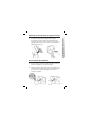
Fix at a height of approximately 1.5m from the fl oor,
away from draughts or heat sources such a fan-coil
outlets, sunlight or offi ce equipment.
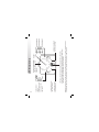
Pipe sensor location
Fix the pipe sensor to the fl ow pipe using the clamping
band supplied.
Important note: It is essential that the circuit in which
the pipe sensor is located is not closed off and that
water circulates past the sensor at all times when the
system is in operation. This may require the fi tting of a
bypass valve between system fl ow and return to ensure
circulation past the sensor.
!
PS1
BYPASS
PS1
GB - Installation Instructions

6
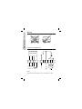
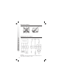
Wiring
2-pipe fan coil application
GB - Installation Instructions
X SEN
X SEN
N
L
FAN
3
FAN
2
FAN
1
COM
O/P
3 SPEED
FAN
ELECTRONICS
OUTPUT
COMMON IN
(LIVE IN)
PS1 PIPE
SENSOR
230 VAC
FIXED 3A
N
Note:
If HEAT/COOL/FAN outputs are 230V, link terminals L-COM

7
GB - Installation Instructions
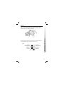
Commissioning
Prior to re-fi tting the thermostat to the wallplate, the DIL
switches on the rear of the unit must be set to the desired
setting.
DIL Switch options, shown in factory set position
(all switches in On position)
ON
ON/OFF
CHRONO
˚C
˚F
Sw On
4
3
2
1
CHRONO 3CHRONO 6

8
DIL Switch descriptions
Switch 4: If set to On/Off, both heating and cooling stages
operate in on/off mode. If set to Chrono, heating
stage operates in chrono-proportional modes,
cooling continues in On/off mode
Switch 3: Active only if switch 4 is set to Chrono. This
switch determines the number of cycles per hour
that the thermostat will impose on the system,
the options are three 20 minute cycles or six 10
minute cycles
Switch 2: Allows Celsius or Fahrenheit temperature scaling
to be selected
Switch 1: Not used in this model
GB - Installation Instructions

9
GB - Installation Instructions
Mounting thermostat to the wallplate
To mount the thermostat to the wallplate, align the
tabs on the top of the thermostat with the apertures in
the wallplate and hinge the thermostat down, pressing
fi rmly to engage the securing clip in the wallplate.
Locking & limiting
To lock or limit the setting range turn the setting dial to 3
and remove knob.
Position the locking springs on the rear of the dial to the
desired position and re-mount the knob ensuring that
number 3 on the dial aligns with the reference mark
on the case.

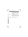
10
Fan runs continuously
Fan runs with heat or
cool demand
Thermostat off
LED lit green when
thermostat is powered
LED lit orange when
fan running
LCD display shows actual room temperature unless knob is moved at which time
a fl ashing set temperature is momentarily displayed. During heating demand a
fl ame symbol is lit, during cooling demand a snowfl ake symbol is lit
LED lit green during
heating or cooling demand
Fan speed 3
Fan speed 2
Fan speed 1
Temperature setting dial,
read setting off LCD display
Note: Should it be necessary to reset the microprocessor for any reason, a reset button is located beneath the setting dial. Use
a non-metallic point, for example a matchstick, to depress the recessed button.
GB - User Instructions
RESET
button

11
Remarque:
Ce produit doit être installé exclusivement par un
électricien qualifi é ou un installateur de chauffage
compétent et doit être conforme à la version en
vigueur des réglementations de câblage IEEE.
Instructions
d’installation
F
F - Instructions d’installation
Thermostat features
Plage de températures, chauffage 5-30°C
Temp de commutation
- Refroidissement à Chauffage
- Chauffage à Refroidissement
> 30°C
< 16°C
Sélecteur de vitesse manuel du
ventilateur
Sélecteur arrêt/automatique
thermostat & marche ventilateur
Alimentation 230 Vac ± 15%, 50/60Hz
Sorties relais, chauffage/
refroidissement & ventilateur
2 x SPST, 3(1)A, 10-230 Vac,
Type 1B
Dimensions (mm)
110 largeur, 90 hauteur, 40 épaisseur
Normes de fabrication EN60730-2-9
Tension de choc nominale 2.5Kv
Essai à la bille 75°C
Niveau de recyclage Degré 2
Précision de la température ±1°C
Specifi cations

12
F - Instructions d’installation
Vue d’ensemble du produit
Le thermostat est conçu pour être utilisé sur des systèmes
équipés d’évaporateurs à ventilation forcée desservis par
un système de commutation central 2 tuyaux. Le thermostat
commande le fonctionnement d’un robinet motorisé qui, pendant
les périodes de chauffage, s’ouvre lorsqu’un chauffage est requis
et, pendant les périodes de refroidissement, s’ouvre lorsqu’un
refroidissement est requis.
La commutation du chauffage au refroidissement s’effectue
automatiquement en mesurant la température du tuyau
d’écoulement. Si la température d’écoulement dépasse 30°C, le
thermostat fonctionne comme un thermostat de chauffage, et si
la température d’écoulement est inférieure à 16°C, le thermostat
fonctionne comme un thermostat de refroidissement.
Remarque importante: Il est primordial que le circuit
dans lequel se trouve le capteur de tuyau ne soit pas
fermé et que l’eau traverse le capteur en permanence.
Ceci peut nécessiter l’installation d’un robinet de
dérivation entre l’écoulement et le retour du système à
l’extrémité de chaque circuit.
Installation
Retirez tout d’abord la plaque murale de l’arrière de l’appareil..
Vous devez disposer d’espacements d’au moins 50 mm au-
dessus et 100 mm en-dessous afi n de pouvoir monter le
module enfi chable.
!

13
Fixez l’appareil à une hauteur d’environ 1,5 m du sol, à
l’écart des courants d’air ou des sources de chaleur telles
que radiateurs, fl ammes nues ou lumière directe du soleil.
Emplacement du capteur de tuyau
Fixer le capteur de tuyau sur le tuyau d’écoulement à
l’aide du collier de serrage fourni.
Remarque importante: Il est primordial que le circuit
dans lequel se trouve le capteur de tuyau ne soit pas
fermé et que l’eau traverse le capteur en permanence.
Ceci peut nécessiter l’installation d’un robinet de
dérivation entre l’écoulement et le retour du système à
l’extrémité de chaque circuit.
!
PS1
BYPASS
PS1
F - Instructions d’installation
Dérivation

14
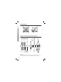
Application évaporateur à ventilation forcée 2 tuyaux
F - Instructions d’installation
X SEN
X SEN
N
L
COM
O/P
Ventilateur
3 vitesses
Electronique
Sortie
Entrée commun
(Entrée phase)
Capteur de
tuyau PS1
230 VCA
3A Fixe
N
Câblage
Remarque:
Si les sorties CHAUFFAGE/REFROIDISSEMENT/VENTILATEUR sont de
230V, relier les bornes L – COM

15
F - Instructions d’installation
ON
Marche/Arrêt
˚C
˚F
Sw On
4
3
2
1
CHRONO
CHRONO 3
CHRONO 6
Instructions
Avant de remonter le thermostat sur le support mural, les inter-
rupteurs à DRC à l’arrière de l’appareil doivent être placés dans
les positions de réglage désirées.
Options interrupteurs à DRC, illustrés en position réglés en usine
(tous les interrupteurs en position Marche)

16
Interrupteur 4: En position Marche/Arrêt, la phase de
chauffage et la phase de refroidissement
fonctionnent en mode marche/arrêt. En
position Chrono, la phase de chauffage
fonctionne en mode chrono-proportionnel, le
refroidissement continue de fonctionner en
mode Marche/Arrêt
Interrupteur 3: Activé uniquement si l’interrupteur 4 est en
position Chrono. Cet interrupteur déter-
mine le nombre de cycles par heure que le
thermostat imposera au système, les options
sont trois cycles de 20 minutes ou six cycles
de 10 minutes
Interrupteur 2: Permet de sélectionner les échelles de
température Celsius ou Fahrenheit
Interrupteur 1: Non utilisé sur ce modèle
F - Instructions d’installation
Descriptions des interrupteurs à DRC

17
F - Instructions d’installation
Fixation du thermostat au support mural
Pour fi xer le thermostat au support mural, aligner
les ergots sur la partie supérieure du thermostat aux
ouvertures du support mural et rabattre le thermostat, en
appuyant fermement pour enclencher le clip de fi xation
dans le support mural.
Verrouillage & Limitation
Pour verrouiller ou limiter la plage de réglage, tourner le
cadran de réglage sur 3 et retirer le bouton.
Placer les ressorts de blocage à l’arrière du cadran à la
position désirée et remonter le bouton en s’assurant que
le chiffre 3 sur le cadran soit aligné à la marque de
repère sur le boîtier.

18
F - Instructions d’utilisateur
Le ventilateur tourne en continu
Le ventilateur tourne avec la
demande de chauffage ou de
refroidissement
Thermostat arrêté
La diode est allumée en
vert lorsque le thermostat
est sous tension
La diode est allumée en
orange lorsque le ventila-
teur tourne
L’écran LCD affi che la température ambiante effective, sauf si le bouton est actionné, cas dans lequel la température
défi nie s’affi che momentanément. Pendant la demande de chauffage, un symbole de fl amme est allumé; pendant la
demande de refroidissement, un symbole de fl ocon de neige est allumé.
La diode est allumée en
vert pendant la demande
de chauffage ou de
refroidissement
Vitesse de ventilateur 3
Vitesse de ventilateur 2
Vitesse de ventilateur 1
Cadran de réglage de
température, lire le réglage
sur l’écran LCD
Remarque: S’il est nécessaire de réinitialiser le micro-processeur pour une raison quelconque, un bouton de réinitialisation se
trouve sous le cadran de réglage. Utiliser une pointe non métallique, par exemple une allumette, pour enfoncer le bouton encastré.
Bouton
REINITIALISER

19
Bitte beachten:
Dieses Produkt darf nur von einem qualifi zierten
Elektriker oder Heizungsinstallateur und gemäß den
aktuellen IEEE-Bestimmungen installiert werden.
Installations-
anweisungen
D
D - Installationsanweisungen
Technische Daten RET 230 HCW-3
Temperaturbereich, Heizen 5-30 °C
Umschaltungstemperatur
- Kühlen zu Heizen
- Heizen zu Kühlen
> 30 °C
< 16 °C
Manuelle Wahl der Ventilatorstufe
Wahlschalter für Thermostat
Aus/Automatik/Ventilator Ein
Stromversorgung
230 Vac ± 15 %, 50/60 Hz
Relaisausgänge, Heizen/Kühlen
und Ventilator
2 x SPST, 3(1)A, 10-230 Vac,
Typ 1B
Abmessungen (B x H x T)
110 x 90 x 40 mm
Bauart EN60730-2-9
Nennimpulsspannung 2.5 Kv
Verformbarkeit unter Druck
75 °C
Emissionswerte Grad 2
Temperaturgenauigkeit ±1 °C
Technische Daten

20
D - Installationsanweisungen
Produktübersicht
Der Thermostat ist für den Einsatz in Heiz-und Kühlsystemen
im 2-Rohr-System mit Ventilator-Luftkühlern gedacht, wobei
die Umschaltung von Heizen auf Kühlen über ein zentrales
Umschaltsystem erfolgt. Der Thermostat regelt den Betrieb
eines elektrischen Ventils, das während der Heizperiode den
Wärmebedarf und während der Kühlperiode den Kühlbedarf
regelt.
Der Übergang von Heizen auf Kühlen erfolgt automatisch
durch Temperaturmessung am Vorlaufrohr. Übersteigt
die Temperatur 30 °C, arbeitet der Thermostat als
Heizthermostat, bei Temperaturen unter 16°C als
Kühlthermostat.
Wichtiger Hinweis: Der Kreislauf, in dem sich der
Anlegefühler befi ndet, darf nicht gesperrt sein und
Wasser muss jederzeit am Fühler vorbeifl ießen. Hierzu
kann u. U. der Einbau eines Bypass-Ventils zwischen
Systemfl uss und Rücklauf am Ende jedes Heiz-/
Kühlkreises erforderlich sein.
Installation
Entfernen Sie zuerst die Wandplatte auf der Geräterückseite
Um das Einsteckmodul zu befestigen, sind 30 mm nach
oben und 100 mm nach unten freizuhalten.
!
La page est en cours de chargement...
La page est en cours de chargement...
La page est en cours de chargement...
La page est en cours de chargement...
La page est en cours de chargement...
La page est en cours de chargement...
La page est en cours de chargement...
La page est en cours de chargement...
La page est en cours de chargement...
La page est en cours de chargement...
La page est en cours de chargement...
La page est en cours de chargement...
La page est en cours de chargement...
La page est en cours de chargement...
La page est en cours de chargement...
La page est en cours de chargement...
La page est en cours de chargement...
La page est en cours de chargement...
La page est en cours de chargement...
La page est en cours de chargement...
La page est en cours de chargement...
La page est en cours de chargement...
La page est en cours de chargement...
La page est en cours de chargement...
La page est en cours de chargement...
La page est en cours de chargement...
La page est en cours de chargement...
La page est en cours de chargement...
La page est en cours de chargement...
La page est en cours de chargement...
La page est en cours de chargement...
La page est en cours de chargement...
La page est en cours de chargement...
La page est en cours de chargement...
La page est en cours de chargement...
La page est en cours de chargement...
La page est en cours de chargement...
La page est en cours de chargement...
La page est en cours de chargement...
La page est en cours de chargement...
La page est en cours de chargement...
La page est en cours de chargement...
La page est en cours de chargement...
La page est en cours de chargement...
La page est en cours de chargement...
La page est en cours de chargement...
La page est en cours de chargement...
La page est en cours de chargement...
La page est en cours de chargement...
La page est en cours de chargement...
La page est en cours de chargement...
La page est en cours de chargement...
La page est en cours de chargement...
La page est en cours de chargement...
La page est en cours de chargement...
La page est en cours de chargement...
La page est en cours de chargement...
La page est en cours de chargement...
La page est en cours de chargement...
La page est en cours de chargement...
La page est en cours de chargement...
La page est en cours de chargement...
La page est en cours de chargement...
La page est en cours de chargement...
-
 1
1
-
 2
2
-
 3
3
-
 4
4
-
 5
5
-
 6
6
-
 7
7
-
 8
8
-
 9
9
-
 10
10
-
 11
11
-
 12
12
-
 13
13
-
 14
14
-
 15
15
-
 16
16
-
 17
17
-
 18
18
-
 19
19
-
 20
20
-
 21
21
-
 22
22
-
 23
23
-
 24
24
-
 25
25
-
 26
26
-
 27
27
-
 28
28
-
 29
29
-
 30
30
-
 31
31
-
 32
32
-
 33
33
-
 34
34
-
 35
35
-
 36
36
-
 37
37
-
 38
38
-
 39
39
-
 40
40
-
 41
41
-
 42
42
-
 43
43
-
 44
44
-
 45
45
-
 46
46
-
 47
47
-
 48
48
-
 49
49
-
 50
50
-
 51
51
-
 52
52
-
 53
53
-
 54
54
-
 55
55
-
 56
56
-
 57
57
-
 58
58
-
 59
59
-
 60
60
-
 61
61
-
 62
62
-
 63
63
-
 64
64
-
 65
65
-
 66
66
-
 67
67
-
 68
68
-
 69
69
-
 70
70
-
 71
71
-
 72
72
-
 73
73
-
 74
74
-
 75
75
-
 76
76
-
 77
77
-
 78
78
-
 79
79
-
 80
80
-
 81
81
-
 82
82
-
 83
83
-
 84
84


Danfoss RET230 HCW3 Guide d'installation
- Taper
- Guide d'installation
dans d''autres langues
- italiano: Danfoss RET230 HCW3 Guida d'installazione
- English: Danfoss RET230 HCW3 Installation guide
- español: Danfoss RET230 HCW3 Guía de instalación
- Deutsch: Danfoss RET230 HCW3 Installationsanleitung
- Nederlands: Danfoss RET230 HCW3 Installatie gids
- dansk: Danfoss RET230 HCW3 Installationsvejledning
- polski: Danfoss RET230 HCW3 Instrukcja instalacji
Documents connexes
-
Danfoss RET230 HCW1 Guide d'installation
-
-
-
-
-
-
-
-
-