
®
RMM4 Rack Mount 1
The RMM4 is a 1RU rack mount carriage with a built-in power
supply. The assembly accepts up to four mini modules, such
as Video Modulators, Video or Audio Switching Modules, etc.
® is a registered trademark of the R. L. Drake Company
© Copyright 1998 R. L. Drake Co. P/N: 3852477A-7-1998 Printed in the U. S. A.
MODULE INSTALLATION
All mini modules install through one of the four openings in the
front panel of the RMM4. Each module is installed with the
handle toward the right-hand side of the RMM4 unit. Each
module should be secured with #4-40 x 1/2" screws via
mounting tabs/holes at the four corners of each module. DC
power cable connections, and any other module-to-module
interconnections, should be made to each module prior to
mounting the RMM4 system into the rack. Observe proper
polarity of cable connectors.
RACK MOUNTING
Adequate ventilation is very important in multi-channel installa-
tions. Units should be spaced apart by at least one panel height
wherever possible, and some air movement is advisable in en-
closed rack cabinets. Excessive heat will shorten component
life and system performance will be degraded without proper cool-
ing.
The power supply features a universal input voltage switching
power supply with attached 115 VAC line cord and four
separate DC output cables with polarized 3-circuit connectors.
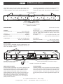
FIGURE 1 - Front Panel View of RMM4.
Space allows for up to four mini-modules
(modules not included).
Standoffs (16 total), located at the
four corners of each module.
DC Power Cables (4) typical.
(Observe proper polarity and maximum ratings.)
AC Cord
FIGURE 2 - Rear Panel View of RMM4
Power Supply Module
SPECIFICATIONS:
GENERAL
Power Requirements: ------------------------------ 100 VAC to 240 VAC
(and -10%/+10% of end limits).
Frequency: ---------------------------------------------------------- 50/60 Hz.
AC Input Power: ------------------------------------------------- 30 WATTS.
Temperature Range: ------------------------------------------ 0 to +50
0
C.
Output Voltages: ---------------------- +12 VDC @ 1.5A (WHITE wire),
+5 VDC @ 1.5A (RED wire),
(BLACK wire = Ground).
CONNECTORS
AC Line Cord ----------------- Attached, with North American plug.
(Power supply module is internally fused: 2A, 250V, SLO-BLO,
5x20 mm. Power supply module also employs current sense
limiting protection).
DC Output: -------------------------- Four separate cables with 3-CKT
Molex connector, female, polarized.
MECHANICAL
Dimensions: (WxHxD): --------------------- 19 in. x 1.75 in. x 8.5 in.,
(40.1 cm x 4.4 cm x 21.6 cm).
Weight: ----------------------------------------------------- 2.8 lbs. (1.3 kgs).
INSTALLATION
Secure modules to the RMM4 using the supplied #4-40 x 1/2"
PAN PHL screws (R. L. Drake part # 3320351) at the four cor-
ners of each module as shown.

2 Important Safeguards
WARNING:
TO REDUCE THE RISK OF ELECTRIC
SHOCK,
DO NOT REMOVE POWER SUPPLY COVERS
NO USER-SERVICABLE PARTS INSIDE
REFER SERVICING TO QUALIFIED PERSONNEL
RISK OF ELECTRIC SHOCK
DO NOT OPEN
¡WARNING!
WARNING: TO PREVENT FIRE OR
ELECTRICAL SHOCK DO NOT
EXPOSE TO RAIN OR MOISTURE
An appliance and cart combination should be moved with care. Quick stops,
excessive force and uneven surfaces may cause the appliance and cart combina-
tion to overturn.
The lightning flash with arrow head symbol, within an equilateral triangle, is
intended to alert the user to the presence of uninsulated "dangerous voltage"
within the product's enclosure that may be of sufficient magnitude to constitute a
risk of electric shock to persons.
The exclamation point within an equilateral triangle is intended to alert the user to
the presence of important operating and maintenance (servicing) instructions in
the literature accompanying the appliance.
TO REDUCE THE RISK OF FIRE OR ELECTRIC SHOCK, DO NOT
EXPOSE THIS APPLIANCE TO RAIN OR MOISTURE. DO NOT
OPEN THE CABINET, REFER SERVICING TO QUALIFIED PER-
SONNEL ONLY.
WARNING:
when it is left unattended and unused for long periods of time, unplug it from the wall
outlet.
14. Power Lines—An outside antenna system should not be located in the vicinity
of overhead power lines, other electric light or power circuits, where it can fall into
such power lines or circuits. When installing an outside antenna system, extreme
care should be taken to keep from touching such power lines or circuits as contact
with them may be fatal.
15. Overloading—Do not overload wall outlets and extension cords as this can
result in a risk of fire or electric shock.
16. Object and Liquid Entry—Never push objects of any kind into this product
through openings as they may touch dangerous voltage points or short-out parts that
could result in a fire or electric shock. Never spill liquid of any kind on the product.
17. Servicing—Do not attempt to service this product yourself as opening or
removing covers may expose you to dangerous voltage or other hazards. Refer all
servicing to qualified service personnel.
18. Damage Requiring Service—Unplug this product from the wall outlet and refer
servicing to qualified service personnel under the following conditions:
a. When the power-supply cord or plug is damaged.
b. If liquid has been spilled, or objects have fallen into the product.
c. If the product has been exposed to rain or water.
d. If the product does not operate normally by following the operating instructions.
Adjust only those controls that are covered by the operating instructions. An improper
adjustment may result in damage and will often require extensive work by a qualified
technician to restore the product to its normal operation.
e. If the product has been dropped or the cabinet has been damaged.
f. When the product exhibits a distinct change in performance—this indicates a need
for service.
19. Replacement Parts—When replacement parts are required, be sure the service
technician has used replacement parts specified by the manufacturer or have the
same characteristics as the original parts. Unauthorized substitutes may result in fire,
electric shock or other hazards.
20. Safety Check—Upon completion of any service or repairs to this product, ask the
service technician to perform safety checks to determine that the product is in proper
operating condition.
21. Outdoor Antenna Grounding—Before attempting to install this product, be sure
the antenna or cable system is grounded so as to provide some protection against
voltage surges and built-up static charges.
a. Use No.10 AWG (5.3mm
2
) copper, No.8 AWG (8.4mm
2
) aluminum, No.17 AWG
(1.0mm
2
) copper-clad steel or bronze wire or larger, as ground wire.
b. Secure antenna lead-in and ground wires to house with stand-off insulators spaced
from 4 feet (1.22m) to 6 feet (1.83m) apart.
c. Mount antenna discharge unit as close as possible to where lead-in enters house.
d. A driven rod may be used as the grounding electrode where other types of electrode
systems do not exist. Refer to the National Electrical Code, ANSI/NFPA 70-1990 for
information.
e. Use jumper wire not smaller than No.6 AWG 13.3mm
2
) copper or equivalent, when
a separate antenna grounding electrode is used.
POUR PREVENIR LES CHOCS ELECTRIQUES, NE PAS
UTILISER CETTE FICHE POLARISEE AVEC UN
PROLONGATEUR, UNE PRISE DE COURANT OU UNE AU-
TRE SORTIE DE COURANT, SAUF SI LES LAMES PEUVENT
ETRE INSEREES A FOND SANS EN LAISSER AUCUNE
PARTIE A DECOUVERT.
ATTENTION:
CAUTION:
TO PREVENT ELECTRIC SHOCK, DO NOT USE THIS (POLAR-
IZED) PLUG WITH AN EXTENSION CORD RECEPTACLE OR
OTHER OUTLET UNLESS THE BLADES CAN BE FULLY INSERTED
TO PREVENT BLADE EXPOSURE.
1. Read Instructions—All the safety and operating instructions should be read
before the appliance is operated.
2. Retain Instructions—The safety and operating instructions should be retained
for future reference.
3. Heed Warnings—All warnings on the appliance should be adhered to.
4. Follow Instructions—All operating and use instructions should be followed.
5. Cleaning—Unplug this appliance from the wall outlet before cleaning. Do not
use liquid cleaners or aerosol cleansers. Use a damp cloth for cleaning.
6. Do Not Use Attachments—not recommended by the manufacturer or they may
cause hazards.
7. Water and Moisture—Do not use this product near water—for example, near a
bathtub, wash bowl, kitchen sink, laundry tub, in a wet basement, or near a
swimming pool—and the like.
8. Accessories—Do not place this product on an unstable cart, stand, tripod,
bracket, or table. The product may fall, causing serious injury to a child or adult,
and serious damage to the appliance.
9. Ventilation—This video product should never be placed near or over a radiator
or heat register. This video product should not be placed in a built-in installation
such as a bookcase or rack unless proper ventilation is provided or the manufac-
turer’s instructions have been adhered to. Any slots or openings in the cabinet are
provided for ventilation. To ensure reliable operation of the video product and to
protect it from overheating, these openings must not be blocked or covered. The
openings should never be blocked by placing the product on a bed, sofa, rug, or
other similar surface.
10. Grounding or Polarization—This video product is equipped with a 3- wire line
cord. It is intended for use with a 3-wire properly grounded power socket. Do not
defeat the safety purpose of the supplied line cord and plug.
10A. Mise à la terre ou Polarisation—Cet appareil est équipé avec un cordon
d'alimentation à trois fils. Il est a brancher sur une prise ayant un connecteur a la
terre. Assurez-vous que la connection a la terre ne manque pas.
11. Power Sources—This product should be operated only from the type of power
source indicated on the marking label. If you are not sure of the type of power
supplied to your home, consult your appliance dealer or local power company.
12. Power-cord Protection—Power-supply cords should be routed so they are
not likely to be walked on or pinched by items placed upon or against them. Pay
particular attention to cords at plugs, convenience receptacles, and the point where
they exit from the appliance.
13. Lightning—For added protection for this product during a lightning storm, or
NOTE TO CATV SYSTEM INSTALLERS:
THIS REMINDER IS PROVIDED TO CALL THE CATV SYS-
TEM INSTALLER'S ATTENTION TO ARTICLE 820 - 40 OF
THE NEC THAT PROVIDES GUIDELINES FOR PROPER
GROUNDING AND, IN PARTICULAR, SPECIFIES THAT THE
CABLE GROUND SHALL BE CONNECTED TO THE GROUND-
ING SYSTEM OF THE BUILDING, AS CLOSE TO THE POINT
OF CABLE ENTRY AS PRACTICAL.
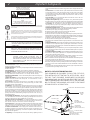
EXAMPLE OF ANTENNA GROUNDING
GROUND CLAMP
GROUND CLAMPS
POWER SERVICE GROUNDING
ELECTRODE SYSTEM
(NEC ART 250, PART H)
ANTENNA
LEAD IN
WIRE
ELECTRIC
SERVICE
EQUIPMENT
GROUNDING
CONDUCTORS
(NEC SECTION 810-21)
ANTENNA
DISCHARGE UNIT
(NEC SECTION 810-20)
-
 1
1
-
 2
2

