Vulcan VCCG24 Le manuel du propriétaire
- Catégorie
- Plaques électriques
- Taper
- Le manuel du propriétaire

©ITW Food Equipment Group, LLC
3600 North Point Blvd.
Baltimore, MD 21222
RETAIN THIS MANUAL FOR FUTURE USE
FORM F-45402 (rev. 10-15)
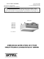
INSTALLATION & OPERATION MANUAL
HEAVY DUTY GAS GRIDDLES
MODELS
VCCG24
VCCG36
VCCG48
VCCG60
VCCG72
VCCG36
For additional information on Vulcan or to locate an authorized parts and
service provider in your area, visit our website at www.vulcanequipment.com

- 2 -
IMPORTANT FOR YOUR SAFETY
THIS MANUAL HAS BEEN PREPARED FOR PERSONNEL QUALIFIED TO
INSTALL GAS EQUIPMENT, WHO SHOULD PERFORM THE INITIAL FIELD
START-UP AND ADJUSTMENTS OF THE EQUIPMENT COVERED BY THIS
MANUAL.
POST IN A PROMINENT LOCATION THE INSTRUCTIONS TO BE FOLLOWED IN
THE EVENT THE SMELL OF GAS IS DETECTED. THIS INFORMATION CAN BE
OBTAINED FROM THE LOCAL GAS SUPPLIER.
IMPORTANT
IN THE EVENT A GAS ODOR IS DETECTED, SHUT
DOWN UNITS AT MAIN SHUTOFF VALVE AND
CONTACT THE LOCAL GAS COMPANY OR GAS
SUPPLIER FOR SERVICE.
FOR YOUR SAFETY
DO NOT STORE OR USE GASOLINE OR OTHER
FLAMMABLE VAPORS OR LIQUIDS IN THE VICINITY OF
THIS OR ANY OTHER APPLIANCE.
IN THE EVENT OF A POWER FAILURE, DO NOT
ATTEMPT TO OPERATE THIS DEVICE.
Improper installation,
adjustment, alteration, service or maintenance
can cause property damage, injury, or death.
Read the installation, operating and maintenance
instructions thoroughly before installing or
servicing this equipment.

- 3 -
TABLE OF CONTENTS
GENERAL…………………………………………………………………………………………...…...…
Specifications……………………………………………………………………….…………….........
INSTALLATION…………………………………………………………………………………………….
Unpacking……………………………………………………………………………………………….
Location………………………………………………………………………………………………….
Installation Codes and Standards…………………………………………………………………….
Griddle Mounted On Stands with Casters……………………………………………………………
Flue Connections……………………………………………………………………………………….
Stands……………………………………………………………………………………………………
Gas Connections………………………………………………………………………………………..
Testing The Gas Supply System………………..……………………………………………………
Gas Pressure Regulation…………..………………………………………………………………….
Electrical Connections …………………………………………………………………………………
OPERATION………………………………………………………………………………………………..
Before First Use…………………………………………………………………………………………
Seasoning The Griddle…………..…………………………………………………………………….
Controls …………………..……………………………………………………………………………..
Startup Of Griddle………………………….…………………………………………………………...
Shutdown Of Griddle…………………………………....……………………………………………..
Extended Shutdown Of Griddle………..……………………………………………………………..
Using The Griddle………..…………………………………………………………………………….
Zone Cooking……………………………………………………………………………………………
CLEANING……..…………………………………………………………………………………………..
Cleaning The Standard Steel Griddle Plate Cooking Surface………………………………….…
Cleaning The Optional Chrome Griddle Griddle Plate Cooking Surface ….…………………….
Cleaning The Optional Rapid Recovery™ Griddle Plate Cooking Surface …………………..…
ADJUSTMENTS…………………………………………………………………………………………….
Calibration……………………………………………….….…………………………………………..
Leveling………………………………………………………………………………..………………..
MAINTENANCE…………………………………………………………………………………………….
General….……………………………………………………………………………………………….
Vent………………………………………………………………………………………………………
Service and Parts Information…………………………………………………………………………
TROUBLESHOOTING……………………………………………………………………………………
ACCESSORY INSTALLATION…………………………………………………………………………..
4
4
4
4
4
5
5
6
6
6
6
7
7
7
7
8
8
9
10
10
10
10
11
12
13
13
14
14
15
15
15
15
15
16
17

- 4 -
INSTALLATION, OPERATION AND CARE OF
HEAVY DUTY GAS GRIDDLES
GENERAL
VCCG Heavy Duty Gas Griddles are produced with quality workmanship and materials. Proper
installation, usage and maintenance of your griddle will result in many years of satisfactory
performance.
Thoroughly read this entire manual and carefully follow all of the instructions provided.
Model
Number of
Burners
BTU/hr Input
Standard Infrared Burner
BTU/hr Input
Optional
U-Shaped Burner
Natural Gas
Propane Gas
VCCG24
2
48,000
44,000
60,000
VCCG36
3
72,000
66,000
90,000
VCCG48
4
96,000
88,000
120,000
VCCG60
5
120,000
110,000
150,000
VCCG72
6
144,000
132,000
180,000
INSTALLATION
Before installing, verify that the type of gas supply (natural gas or propane) agrees with the
specifications on the rating plate located on the outside right of the unit. If the supply and
equipment requirements do not agree, do not proceed with the installation. Contact your dealer
immediately. It is recommended that a trained gas service technician with the necessary tools,
instruments and skills perform the installation of the griddle.
UNPACKING
This griddle was inspected before leaving the factory. The carrier assumes full responsibility for the
safe delivery upon acceptance of the shipment. Check for possible shipping damage immediately after
receipt.
If the griddle is found to be damaged, complete the following steps:
1. Carrier must be notified within 5 business days of receipt.
2. Carrier’s local terminal must be notified immediately upon discovery (note time, date, and
who was spoken to), and follow up and confirm with written or electronic communication.
3. All original packing materials must be kept for inspection purposes.
4. The griddle cannot have been moved, installed, or modified.
5. Notify Vulcan Customer Service immediately at 800-814-2028.
Carefully unpack your griddle and make sure that no parts are discarded with packaging material.
LOCATION
The installation location must be kept free and clear of combustibles. When installing, never
enclose the bottom of the griddle with a raised curb or other constructions that would obstruct
flow of air into or out of the griddle. Adequate clearance for air openings into the combustion
chamber must be provided. Make sure there is an adequate supply of air in the room to replace
air taken out by the ventilation system.

- 5 -
Do not permit air to blow directly at the griddle. Avoid open windows next to the griddle
wherever possible. Avoid wall-type fans which create air cross-currents within the room.
This griddle is Design Certified for installation on a non-combustible counter with 4” legs,
or combustible floor with a stand.
INSTALLATION CLEARANCES
COMBUSTIBLE CONSTRUCTION
NON-COMBUSTIBLE CONSTRUCTION
Back:
6”
0”
Right
Side:
6”
0”
Left Side
6”
0”
INSTALLATION CODES AND STANDARDS
The griddle must be installed in accordance with:
In the United States of America:
1. State and local codes.
2. National Fuel Gas Code, ANSI-Z223.1/NFPA #54 (latest edition). This shall include but
not be limited to: NFPA #54 Section 10.3.5.2 for Venting. Copies may be obtained
from The American Gas Association Accredited Standards Committee Z223, @ 400
N. Capital St. NW, Washington, DC 20001 or the Secretary Standards Council, NFPA,
1 Batterymarch Park Quincy, MA 02169-7471
NOTE: In the Commonwealth of Massachusetts
All gas appliances vented through a ventilation hood or exhaust system equipped with
a damper or with a power means of exhaust shall comply with 248 CMR.
3. NFPA Standard # 96 Vapor Removal from Cooking Equipment, latest edition, available
from the National Fire Protection Association, Batterymarch Park, Quincy, MA 02269.
In Canada:
1. Local codes.
2. CAN/CSA-B149.1 Natural Gas Installation (latest edition)
3. CAN/CSA-B149.2 Propane Installation Code (latest edition), available from the
Canadian Gas Association, 178 Rexdale Blvd., Etobicoke, Ontario, Canada M9W 1R3
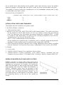
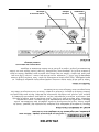
GRIDDLES MOUNTED ON STANDS WITH CASTERS
Griddles mounted on stands with casters must use a
flexible connector (not supplied) that complies with the
Standard for Connectors for Movable Gas Appliances
ANSI Z21.69•CSA6.16, and a quick -disconnect device
that complies with Gas Fuel, ANSI Z21.3•CSA6.9. In
addition, adequate means must be provided to limit
movement of the appliance without depending on the
connector and the quick-disconnect device (or its
associated piping) to limit appliance movement. Attach
the restraining device at the rear of the griddle as
shown.

- 6 -
If disconnection of the restraint is necessary, turn off the gas supply before
disconnecting. Reconnect the restraint prior to turning the gas supply on and returning
the griddle to its installation position.
Casters are only supplied on a griddle stand. If the griddle is moved for any reason the
griddle should be re-leveled (see LEVELING in this manual).
FLUE CONNECTIONS
Do not obstruct the flow of flue gases from the flue, located at the rear of the griddle. It is
recommended that flue gases be ventilated to the outside of the building through a
ventilation system installed by qualified personnel.
From the termination of the flue to the filters of the hood venting system, a minimum
clearance of 18” must be maintained.
Information on the construction and installation of ventilating hoods may be obtained from
the standard for “Vapor Removal from Cooking Equipment”, NFPA No. 96 (latest edition),
available from the National Fire Protection Association, Batterymarch Park, Quincy, MA
02269.
STANDS
The griddle has an optional stainless steel stand with locking casters.
GAS CONNECTIONS
Gas supply connections and any pipe joint compound must be
resistant to the action of propane gases.
Use a ¾” NPT gas supply line for the griddle inlet, located at the rear of the griddle. All
flexible and semi-rigid gas supply lines must comply with the applicable ANSI standard.
To ensure maximum operating efficiency this appliance must be connected with a gas
supply line of solid pipe or a commercial type Flexible Connector with the net inside
diameter (I.D.) as large as or larger than the gas pipe inlet on this appliance. Codes
require that a gas shutoff valve must be installed in the gas line upstream of the griddle.
Prior to lighting, check all joints in the gas supply line for leaks.
Use soap and water solution. Do not use an open flame.
After checking for leaks all lines receiving gas should be fully purged to remove air.
TESTING THE GAS SUPPLY SYSTEM
When the gas supply pressure exceeds ½ psig (3.45 kPa), the griddle and its individual
shutoff valve must be disconnected from the gas supply piping system.
When the gas supply pressure is ½ psig (3.45 kPa) or less, the griddle should be isolated
from the gas supply system by closing its individual manual shutoff valve.

- 7 -
GAS PRESSURE REGULATION
The VCCG griddle is constructed with internal gas regulators on each burner valve. The
valves are pre set to 4” W.C. on natural gas units or 10” W.C. on propane gas units. An
external gas regulator is not required as long as the gas pressure supplied to the unit is
not greater than ½ psig (3.45 kPa) or 14” W.C. The recommended supply pressure
(upstream of the griddle) should be 7-9” W.C. for natural gas and 11-12” W.C. for propane
gas.
At no time should the griddle be connected to supply pressure greater than ½
psig (3.45 kPa) or 14” W.C.
ELECTRICAL CONNECTIONS
Electrical and grounding connections must comply with the
applicable portions of the National Electrical Code and/or other local electrical
codes.
Disconnect the electrical power to the griddle and follow lockout /
tagout procedures.
Appliances equipped with a flexible electric supply cord are provided
with a three-prong grounding plug. It is imperative that this plug be connected into
a properly grounded three-prong receptacle. If the receptacle is not the proper
grounding type, contact an electrician. Do not remove the grounding prong from
this plug.
Power supply for electric ignition is 120 volts, 2 amp, 50/60 Hertz, 1 phase.
Do not connect the griddle to electrical supply until after gas connections are made.
OPERATION
The griddle and its parts are hot. Use care when operating, cleaning
or servicing the griddle.
BEFORE FIRST USE
Remove all packing material and protective plastic from the surfaces of the unit. Before
leaving the factory the griddle is coated with vegetable oil as a rust inhibitor. Remove this
film when the griddle plate is being cleaned prior to its first cooking use. Heat the griddle
to 200-300°F to loosen and melt the coating, then clean the surface by adding water or
a non-corrosive, grease dissolving commercial cleaner, following the manufacturer’s
directions. Scrape the oil residue from the plate with a griddle scraper. Rinse thoroughly
and wipe dry with a soft clean cloth. Clean all accessories.

- 8 -
SEASONING THE GRIDDLE
Season the griddle to avoid possible surface corrosion before first use, and after every
cleaning. This will also help reduce the sticking of cooked food product. Heat griddle to a
low temperature (300-350°F) and apply a small amount of cooking oil – about one ounce
per square foot of surface. Use a soft lint-free cloth to spread the oil over the entire
griddle surface to create a thin film. Wipe off any excess oil with a cloth. Repeat the
procedure until the griddle has a slick, mirror-like finish.
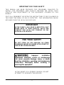
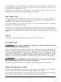
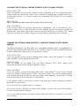
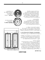
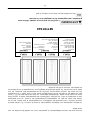
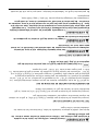
CONTROLS
POWER SWITCH
The VCCG turns off and on by a single power switch. Pushing the power switch to the
ON position is all that is required to put the unit into production once the thermostats
have been set.
IGNITER CYCLE LIGHT
The igniter cycle light is a clear hole where the user can view the diagnostic LED on the ignition
module. In order to view the light, user must have a straight line of sight through the hole to be able to
see the green or red light.
The igniter cycle lights are located at the 8 o’clock position to each corresponding
thermostat knob. There is one pilot and one igniter cycle light for each burner (12” section
of griddle). Once the power switch has been pushed to the ON position, the igniters will
begin to ignite the pilots. The igniter cycle light will flash the color green while attempting
Power Switch
Igniter Cycle Light
Thermostat Cycle Light
Thermostat Knob
Pilot And Burner Sight Slots

- 9 -
to ignite the pilot. Once the pilot is lit and recognized by the igniter safety, the light will
illuminate a steady green color. The pilot must be ignited (burning) and the igniter cycle
light must be emitting a steady green color before the griddle burner will be allowed to
ignite.
If the pilot fails to ignite after approximately 90 seconds, the igniter cycle light will
illuminate a flashing red color that indicates the pilot did not ignite. Pushing the power
switch to the OFF position and then back to the ON position will restart the pilot ignition
cycle and the pilots will attempt to ignite again.
THERMOSTAT KNOB
Each 12” section of the griddle is independently controlled by a solid state thermostat
control. The thermostats have an operating range of 150 to 550 degrees for standard
steel and chrome plate surfaces (150 to 450 degrees for Rapid Recovery™ composite
plate option). The thermostat knobs will need to be turned to a temperature setting for the
burners to ignite. Each 12” griddle section may be turned off independently by setting the
corresponding thermostat to the OFF position. You may also leave all thermostats set at
the desired settings and turn all sections off at once by pushing the power switch to the
OFF position.
THERMOSTAT CYCLE LIGHT
The thermostat cycle lights are located at the 12 o’clock position to each corresponding
thermostat knob. The light will illuminate when the surface cooking temperature drops
below the thermostat knob set point. The illumination of this light indicates that the burner
for that zone is lit.
STARTUP OF GRIDDLE
1. Set all thermostats to the desired temperature set points.
2. Push the power switch to the ON position. The red light behind the ON should
illuminate indicating that electrical power is being supplied to the unit.
3. If the thermostat cycle lights do not illuminate a steady red color within
approximately 90 seconds, push the power switch to OFF and back to ON again, this
will restart the pilot ignition cycle .This process may need to be repeated several times
on the initial installation of the griddle or if the griddle has been disconnected from the
gas supply.
4. Check that all thermostat cycle lights are illuminating a steady red color to verify that
all burners are lit and functioning properly.

- 10 -
SHUTDOWN OF GRIDDLE
Push the power switch to the OFF position, all lights should go off indicating that the
griddle is no longer heating.
EXTENDED SHUTDOWN OF GRIDDLE
1. Push the power switch to the OFF position
1. Shut the main gas supply valve to the OFF position.
2. Unplug the griddle electrical supply cord.
3. Apply a coat of vegetable oil over the griddle plate to inhibit rust.
USING THE GRIDDLE
To preheat, turn the burners on about 20 minutes before cooking.
A uniform and systematic approach to loading the griddle will produce the most consistent
product results.
The griddle plate is steel, but the surface is relatively soft and can be scored or dented by
careless use of a spatula or scraper. Be careful not to dent, scratch, or gouge the plate
surface. Do not try to knock off loose food that may be on the spatula by tapping the
corner or the edge of the spatula on the griddle surface. Use spatulas with rounded
edges. Do not use tempered steel utensils. Do not chop on the griddle cooking surface.
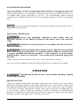
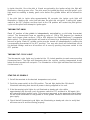
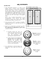
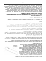
ZONE COOKING
This griddle features infrared box burners in 12” sections (U-shaped burners optional),
each controlled by independent thermostat controllers. Each 12” section is a separate
cooking zone, and allows for cooking a variety of products over a single griddle plate.
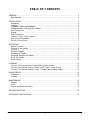
The chart is a suggested usage of zone cooking. When zone cooking, it is suggested that
you start with your lowest temperature setting at either side of the griddle, increasing the
zone temperature as you move up the zone line. Typically, the temperature differential
between the center of one cooking zone to the center of another zone that is directly
adjacent cannot be varied by more than 50 degrees. Some heat transfer from one area to
the next is to be expected. These zone cooking guidelines will vary depending on product
temperatures, size and shape. This guide should be adjusted to suit your product and
operational cooking preference.

- 11 -
ZONE 1
(300°F)
ZONE 2
(350°F)
ZONE 3
(350°F)
ZONE 4
(400°F)
PRODUCT
Sausage
Eggs (Hard Fried)
Eggs (Scrambled)
Burger (Well Done)
Steak (Well Done)
Chicken Breast
Frozen Foods
Pork Chops
PRODUCT
PRODUCT
Steak (Rare)
Stir Fry Vegetables
Salmon
Fish Cakes
Lobster
Scampi
Pancakes
French Toast
Bacon
Omelet
Hash Browns
Canadian Bacon
Eggs (Sunny Side Up)
Boiled Ham
Steak (Medium Well)
Fresh Burger (Medium Well)
Small Frozen Burger (Medium Well)
CLEANING
The griddle and its parts are hot. Use care when operating, cleaning
or servicing the griddle.
Do not use a water jet stream to clean the griddle.
Empty the grease drawer as needed throughout the day and regularly clean at least once
daily.
Clean the griddle regularly. A clean griddle always looks better, lasts longer and performs
better. To produce evenly cooked, perfectly browned griddle products keep the griddle
plate clean and free of carbonized grease. Carbonized grease on the surface hinders the
transfer of heat from the griddle surface to the food, resulting in spotty browning and loss
of cooking efficiency. Carbonized grease tends to cling to griddle foods, giving them a
highly unsatisfactory and unappetizing appearance.

- 12 -
To keep the griddle clean and operating at peak efficiency, follow these procedures:
AFTER EACH USE
Clean the griddle cooking surface accordingly to the type of surface on your model. See
the specific cleaning instructions by cooking surface finish. Empty the grease drawer
throughout the day as needed.
ONCE PER DAY
Thoroughly clean the griddle back splash, sides and front. Do not hit the backsplash with
a spatula or any other tool. This may create a gap between the splash and griddle plate
that is hard to clean. Remove, empty and wash the grease drawer in the same manner as
an ordinary cooking utensil.
ONCE PER WEEK
Clean the griddle surface thoroughly per the instructions for the surface finish of your
particular model. After cleaning the plate, the griddle should be seasoned according to
the instructions in this manual.
Clean stainless steel surfaces with a damp cloth and polish with a soft dry cloth. To
remove discoloration, use a griddle cleaner.
If the griddle usage is very high, consider conducting this weekly cleaning procedure
more than once per week.
CLEANING THE STANDARD STEEL GRIDDLE PLATE COOKING SURFACE
AFTER EACH USE
Clean the griddle cooking surface regularly with a griddle scraper during the work shift.
ONCE PER DAY
Turn the griddle off and allow it to cool down between 275°F-300°F, apply room
temperature water and clean it with a griddle scraper.
ONCE PER WEEK
Clean the griddle surface thoroughly. Use a griddle brick, screen, or Scotch Bright™ pad
on the surface as necessary. Rub with the grain of the metal while the griddle is still
warm (not hot). A detergent may be used on the plate surface to help clean it, but be sure
the detergent is thoroughly removed by flushing with clear water. After cleaning, reseason
the cooking surface according to the instructions in this manual. If the griddle usage is
very high, consider conducting this weekly cleaning procedure more than once per week.

- 13 -
CLEANING THE OPTIONAL CHROME GRIDDLE PLATE COOKING SURFACE
AFTER EACH USE
Clean the griddle cooking surface regularly with a palmetto brush and a bladed griddle
scraper during the work shift. Never use an abrasive scouring pad or griddle brick on a
chrome plate surface. The chrome surface can be damaged by careless use of a spatula
or scraper.
ONCE PER DAY
Clean chrome surfaces with a damp cloth and polish with a soft dry cloth.
ONCE PER WEEK
If the chrome plate has become carbonized or blackened, use a non-abrasive, non-
silicated cleaner such as Bon Ami®. Be sure the cleaning agent is thoroughly removed by
flushing with clear water. Wipe with a damp cloth and polish with a soft dry cloth. After
cleaning, reseason the cooking surface according to the instructions in this manual.
CLEANING THE OPTIONAL RAPID RECOVERY™ COMPOSITE GRIDDLE PLATE COOKING
SURFACE
The Rapid Recovery™ griddle plate is a composite material which is engineered to
provide a high heat transfer rate to the food. The top surface is stainless steel and can be
scored or dented by careless use of a spatula or scraper.
AFTER EACH USE
Clean the griddle cooking surface regularly with Nemco Easy Grill Scraper™ or similar
type of griddle scraper during the work shift.
ONCE PER DAY
Turn the griddle off and allow it to cool down between 275°F-300°F, apply room
temperature water and clean it with a griddle scraper.
ONCE PER WEEK
Clean the griddle surface thoroughly with water, Scotch-Brite
TM
Quick Clean Griddle
System or Ecolab Grease Express™ High-Temp Grill Cleaner. Be sure the cleaning agent
is thoroughly removed by flushing with clear water. After cleaning, reseason the cooking
surface according to the instructions in this manual.
If the griddle usage is very high, consider conducting this weekly cleaning procedure
more than once per week.
Do not use a brick or griddle stone for cleaning.
Do not use chlorine sanitizer in contact with griddle. Contact can cause discoloration,
corrosion and permanent damage.
Do not use cleaning agents including Sodium Hydroxide, which is common in household
oven cleaners.

- 14 -
ADJUSTMENTS
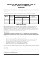
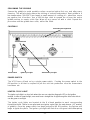
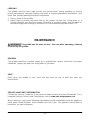
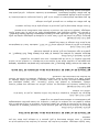
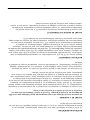
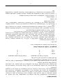
CALIBRATION
1. Each thermostat controls a 12” zone of the
griddle. Using a Surface Probe temperature
measurement device, observe the temperatures
at the center points of the cooking zones.
These points are located by starting 6” from the
side splash (left or right) and every 12” across
the width of the griddle, with all points located
12” back from the front edge of the griddle
plate.
NOTE: Use of infrared thermometers is not
recommended. These devices are highly
sensitive to surface color (clean or dirty), angle
of reading and distance from the unit.
2. Set thermostats to 350°F and allow to stabilize,
allowing the burner to cycle ON and OFF at
least two times.
3. Watch for the thermostat cycle light to go OFF,
then measure the temperature for that zone.
The temperature should be 350°F ±10°F. If not,
continue to Step 4.
4.
a. Carefully loosen the knob set
screw. DO NOT allow the knob to
turn. Carefully remove the knob
from the thermostat shaft,
exposing the temperature dial.
b. Loosen screws on the temperature
dial and adjust so the temperature
indicated by the knob arrow
matches the griddle plate
temperature reading. Knob will
have to be placed back on the
shaft to verify adjustment.
5. Once calibration is achieved, tighten the
temperature dial screws and knob set
screws.
Step 4a. Set knob &
check Temperature.
Remove knob
Step 4b. – Adjust
temperature dial &
verify temperature
setting
Step 5 –Replace
knob & tighten
screws

- 15 -
LEVELING
The griddle must be level (side-to-side and front-to-back) during operation to ensure
proper performance. Improper leveling can result in uneven temperature distribution, cold
spots, and possibly damage electrical components.
1. Place a level on the griddle.
2. Adjust legs by turning the bullet feet at the bottom of each leg. Using pliers or a
crescent wrench, turn the feet counter-clockwise to increase height, and clockwise to
decrease height until leveling is achieved. Do not extend the legs more than 1-¾”.
MAINTENANCE
The griddle and its parts are hot. Use care when operating, cleaning
or servicing the griddle.
GENERAL
The griddle should be checked yearly by a qualified gas service technician for proper
calibration, proper gas pressure and grease or gas leaks.
VENT
Daily, when the griddle is cool, check the flue vent (at rear of unit) and clear any
obstructions.
SERVICE AND PARTS INFORMATION
Contact the Service Contractor in your area to obtain service and parts information. For a
complete listing of Service and Parts depots refer to www.vulcanequipment.com.
When calling for service the following information should be available from the appliance
serial plate: Model Number, Serial Number and Gas Type. The appliance serial plate is
located on the right side panel.

- 16 -
TROUBLESHOOTING
PROBLEM
POSSIBLE CAUSES
Heat does not come on
when individual
thermostat knob is set
1. Cooking surface temp is above set point.
2. Pilot burner not lit.
3. Problem with burner solenoid valves. (Call for service)
4. Problem with thermocouple. (Call for service)
5. Low gas pressure. (Call for service)
Pilot burners will not light
1. Main gas shut-off valve not in On position.
2. Power switch not in ON position.
3. Push power switch to OFF and back to ON to restart pilot
ignition cycle.
4. Problem with safety-ignition module. (Call for service)
5. Obstructed pilot orifice. (Call for service)
6. Low gas pressure. (Call for service)
Pilot burner will not stay
lit
1. Obstructed orifice. (Call for service)
2. Gas supply not purged of air. Air blowing pilot out. (Call
for service)
3. Problem with pilot safety valve. (Call for service)
4. Electrode sensor not in flame. (Call for service)
5. Low gas pressure. (Call for service)
Fat appears to smoke
excessively
1. Temperature set too high.
2. Moisture in food may be turning into steam
Food sticks to griddle or
burned around edges or
contains dark specs
1. Temperature set too high.
2. Griddle surface requires cleaning and/or seasoning.
3. Surface under food not covered with enough cooking oil.
Food under-cooked inside
1. Temperature set too low.
2. Food not cooked for long enough time.
Food tastes greasy or has
objectionable off-flavor
1. Food itself may have off-flavor.
2. Food stored improperly before cooking.
3. Too much griddle fat used.
4. Temperature set too low.
Noticeable build-up of
gum on griddle
1. Temperature set too high.
2. Griddle surface needs cleaning and/or seasoning.
3. Too much griddle fat used.

- 17 -
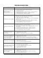
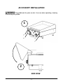
ACCESSORY INSTALLATION
The griddle and its parts are hot. Use care when operating, cleaning
or servicing the griddle.
1
SIDE VIEW
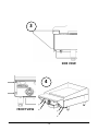
2

- 18 -
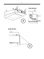
SIDE VIEW
FRONT VIEW
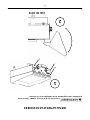
4
3

- 19 -
NOTES

- 19 -
NOTES
La page est en cours de chargement...
La page est en cours de chargement...
La page est en cours de chargement...
La page est en cours de chargement...
La page est en cours de chargement...
La page est en cours de chargement...
La page est en cours de chargement...
La page est en cours de chargement...
La page est en cours de chargement...
La page est en cours de chargement...
La page est en cours de chargement...
La page est en cours de chargement...
La page est en cours de chargement...
La page est en cours de chargement...
La page est en cours de chargement...
La page est en cours de chargement...
La page est en cours de chargement...
La page est en cours de chargement...
-
 1
1
-
 2
2
-
 3
3
-
 4
4
-
 5
5
-
 6
6
-
 7
7
-
 8
8
-
 9
9
-
 10
10
-
 11
11
-
 12
12
-
 13
13
-
 14
14
-
 15
15
-
 16
16
-
 17
17
-
 18
18
-
 19
19
-
 20
20
-
 21
21
-
 22
22
-
 23
23
-
 24
24
-
 25
25
-
 26
26
-
 27
27
-
 28
28
-
 29
29
-
 30
30
-
 31
31
-
 32
32
-
 33
33
-
 34
34
-
 35
35
-
 36
36
-
 37
37
-
 38
38


Vulcan VCCG24 Le manuel du propriétaire
- Catégorie
- Plaques électriques
- Taper
- Le manuel du propriétaire
dans d''autres langues
- English: Vulcan VCCG24 Owner's manual
Documents connexes
Autres documents
-
none I 3003 Guide d'installation
-
Vulcan-Hart 24RRG-ML-135339-00024 spécification
-
Vulcan-Hart MSA48-ML-135238 Manuel utilisateur
-
Wolf Range WCRG48-T Manuel utilisateur
-
Wolf Range WCRG36-T Mode d'emploi
-
Wolf TYG60 Installation & Operation Manual
-
Garland E20 Series Owner Instruction Manual
-
Garland PERFORMER S Series Manuel utilisateur
-
Vulcan-Hart SX60F Mode d'emploi
-
Magikitchn MKG24 Manuel utilisateur