Toro Drive Shield Kit, Power Max Snowthrower Guide d'installation
- Catégorie
- Kits de voiture
- Taper
- Guide d'installation

FormNo.3361-375RevA
DriveShieldKit
PowerMax
®
Snowthrowers
ModelNo.115-5699
InstallationInstructions
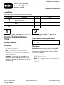
LooseParts
Usethechartbelowtoverifythatallpartshavebeenshipped.
ProcedureDescription
Qty.
Use
1
Nopartsrequired
–
Driveshield1
2
Bolt2
Installthedriveshield.
3
Trimseal1Installthetrimseal.
1
RemovingtheBeltCoversand
CleaningtheSnowthrower
Frame
NoPartsRequired
Procedure
1.Removethe4boltsthatholdthebeltcoversinplace,
andremovethebeltcovers.
Note:Savethescrewstoinstallthebeltcover.
2.Cleananddrythetopofthesnowthrowerframeto
removealloilanddirt.
Important:Thesealantwillnotadheretoa
dirtyframe,andanimpropersealmayallow
moisturetopenetratethesealandleakontothe
frictionwheel.
2
InstallingtheDriveShield
Partsneededforthisprocedure:
1Driveshield
2Bolt
Procedure
Important:YouwillneedaexiblesiliconeRTV
sealant(suchasLoctite5045orLoctite5905)to
completethisprocedure.Thesealantshouldbe
waterandoilresistant.
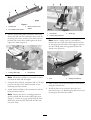
1.Apply2parallelbeadsofsealanttothebottomof
thedriveshield(Figure1).
Note:Donotapplysealantintheareabetweenthe
locatingtabsandthefrontedgeofthedriveshield
(Figure1).
©2008—TheToro®Company
8111LyndaleAvenueSouth
Bloomington,MN55420
Registeratwww.Toro.com.
OriginalInstructions(EN)
PrintedintheUSA
AllRightsReserved

Figure1
1.Locatingtab
3.BeadofsiliconeRTV
sealant
2.Frontedgeofdriveshield
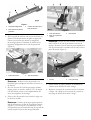
2.Pullthetractionidlerpulleytowardthesideofthe
frame,andslidethedriveshieldintoplace,withthe
mountingtabsontheoutsideoftheframeandthe
positiontabsonthedriveshieldagainstthefront
edgeoftheframe(Figure2).
Figure2
1.Tractionidlerpulley2.Driveshield
Note:Tiltthedriveshieldasyouinstallittomove
itaroundthebeltsandtheengine.
3.Usingthedriveshieldasatemplate,drilla5/32-inch
holeoneachsideoftheframecenteredonthe
mountingtabholelocations.
4.Attachthedriveshieldtothesnowthrowerwiththe
boltsprovidedinthekit.
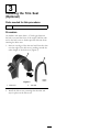
Note:Ensurethatthereisasmallgapbetween
thedriveshieldandthetractionidlerpulleyarm
(Figure3).Ifthereisnogap,gentlybendthedrive
shieldawayfromtheidlerarmuntiltheidlerarm
canmovefreely.
Figure3
1.Driveshield
3.Smallgap
2.Tractionidlerpulleyarm
Note:Insertawedge(suchasascrewdriver)
betweenthetopofthedriveshieldandthebottom
oftheengineonbothsidesoftheenginetoprevent
thedriveshieldfrombowingupwardbeforethe
sealantcures(Figure4).
Figure4
1.Bolt
2.Wedge(Screwdriver)
5.Allowatleast2hoursforthesealanttocurebefore
usingthesnowthrower.
6.Installthebeltcoversusingtheboltsthatyou
removedinstep1of“RemovingtheBeltCoversand
CleaningtheSnowthrowerFrame.”
2

3
InstallingtheTrimSeal
(Optional)
Partsneededforthisprocedure:
1Trimseal
Procedure
Onmodelswithmorethana1/2-inchgapbetween
thebeltcoverandthefrontoftheengine,addthetrim
sealtothebeltcovertofurtherpreventmoisturefrom
enteringthedrivearea.
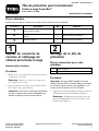
1.Startononeedgeofthetrimsealandforcethetrim
overtheedgeofthebeltcover,workingaroundthe
entirelengthofthebeltcover(Figure5).
Figure5
1.Beltcover2.Trimseal
2.Installthebeltcovers,ensuringthatthetrimseal
staysinplaceonthebeltcover.
3

Notes:
4

FormNo.3361-375RevA
Tôledeprotectionpourtransmission
FraisesàneigePowerMax
®
N°demodèle115-5699
Instructionsdemontage
Piècesdétachées
Reportez-vousautableauci-dessouspourvériersitouteslespiècesontétéexpédiées.
Procédure
Description
Qté
Utilisation
1
Aucunepiècerequise
–
Tôledeprotection1
2
Boulon2
Montezlatôledeprotection.
3
Jointdegarniture1Montezlejointdegarniture.
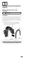
1
Déposeducouverclede
courroieetnettoyagedu
châssisdelafraiseàneige
Aucunepiècerequise
Procédure
1.Retirezles4visdexationducouvercledecourroie
etdéposezlecouvercle.
Remarque:Mettezlesvisdecôtéenprévision
delareposeducouvercle.
2.Nettoyezl'huileetlessaletéssurlehautduchâssis
delafraiseàneige,puisséchez-le.
Important:Lemasticnecollerapassilechâssis
estsale,etlaisseraalorspasserl'humiditéqui
viendrasedéposersurlarouedefriction.
2
Montagedelatôlede
protection
Piècesnécessairespourcette
opération:
1Tôledeprotection
2Boulon
Procédure
Important:UnmasticRTVexibleàbasede
silicone(Loctite5045ouLoctite5905parexemple)
estnécessairepourréalisercetteprocédure.Le
masticdoitêtrerésistantàl'eauetl'huile.
1.Appliquez2cordonsparallèlesdemasticaubasdela
tôledeprotectiondelatransmission(Figure1).
Remarque:N'appliquezpasdemasticentreles
languettesd'alignementetlebordavantdelatôle
deprotection(Figure1).
©2008—TheToro®Company
8111LyndaleAvenueSouth
Bloomington,MN55420
Enregistrezvotreproduitàwww.Toro.com.Traductiondutexted'origine(FR)
ImpriméauxÉtats-Unis
Tousdroitsréservés

Figure1
1.Languetted'alignement
3.CordondemasticRTVà
basedesilicone
2.Bordavantdelatôlede
protection
2.Tirezlapouliedetensionverslecôtéduchâssis,et
glissezlatôledeprotectionenplaceenappuyant
contrelebordavantduchâssisleslanguettes
demontagesituéesàl'extérieurduchâssisetles
languettesd'alignementdelatôledeprotection
(Figure2).
Figure2
1.Pouliedetension2.Tôledeprotection
Remarque:Inclinezlatôledeprotectionen
l'installantpourladéplacerautourdescourroieset
dumoteur.
3.Envousservantdelatôledeprotectioncomme
repère,percezuntroude4mm(5/32")dechaque
côtéduchâssis,centrésurlesemplacementsdes
trousdeslanguettesdemontage.
4.Fixezlatôledeprotectionsurlafraiseàneigeavec
lesboulonsfournis.
Remarque:Vériezqu'unlégerespaceséparela
tôledeprotectionetlebrasdelapouliedetension
(Figure3).Sicen'estpaslecas,échissezlatôle
avecprécautionpourl'écarterdubrasdelapouliede
tensionjusqu'àcequelebrasbougelibrement.
Figure3
1.Tôledeprotection3.Petitespace
2.Brasdelapouliede
tension
Remarque:Insérezuncoin(commeuntournevis)
entrelehautdelatôledeprotectionetlebasdu
moteur,desdeuxcôtésdumoteur,pourempêcherla
tôledeprotectiondesebomberverslehautavantla
prisedumastic(Figure4).
Figure4
1.Boulon
2.Coin(tournevis)
5.Laissezsécherlemasticpendantunminimumde
2heuresavantd'utiliserlafraiseàneige.
6.Montezlecouvercledecourroieaveclesvisretirées
àl'étape1de“Déposeducouvercledecourroieet
nettoyageduchâssisdelafraiseàneige”.
2

3
Montagedujointdegarniture
(option)
Piècesnécessairespourcette
opération:
1Jointdegarniture
Procédure
Surlesmodèlesprésentantunécartdeplusde1,25cm
(1/2")entrelecouvercledecourroieetl'avantdu
moteur,ajoutezlejointdegarnituresurlecouverclede
courroiepourrenforcerlaprotectioncontrel'humidité
delatransmission.
1.Commencezd'uncôtédujointdegarnitureet
forcez-lepeuàpeusurlebordducouverclede
courroiejusqu'aubout(Figure5).
Figure5
1.Couvercledecourroie
2.Jointdegarniture
2.Montezlecouvercledecourroieenveillantàlaisser
lejointdegarnitureenplacesurlecouvercle.
3

-
 1
1
-
 2
2
-
 3
3
-
 4
4
-
 5
5
-
 6
6
-
 7
7
-
 8
8


Toro Drive Shield Kit, Power Max Snowthrower Guide d'installation
- Catégorie
- Kits de voiture
- Taper
- Guide d'installation
dans d''autres langues
Autres documents
-
Simplicity 1695386 Manuel utilisateur
-
-
MTD 31AE664 Le manuel du propriétaire
-
 Poulan Pro PR121ES Le manuel du propriétaire
-
 Poulan Pro PR121ES Le manuel du propriétaire
-
 Poulan Pro PR111 Le manuel du propriétaire
-
 Poulan Pro PR111 Le manuel du propriétaire
-
 Poulan Pro PR100 Le manuel du propriétaire
-
 Poulan Pro PR100 Le manuel du propriétaire


