Marvel MP15WS1F4RP Mode d'emploi

Catégorie
Boissons glacées
Taper
Mode d'emploi
MP15WSG4**
MP15WSF4**
MP24WSG5**
MP24WSF5**
MP24WDG5**
MP24WDF5**
MP24WSG0**
Note: Wine refrigerators / coolers are designed exclusively
for the storage of wine. Wine refrigerators / coolers cannot
attain storage temperatures suitable for fresh food storage.
Remarque : Les réfrigérateur sont conçues exclusivement
pour y garder des vins. Elles ne peuvent pas atteindre des
températures de conservation convenant à l’entreposage
d’aliments frais.
EN Installation, Operation and Maintenance Instructions
FR Instructions d’installation, d’utilisation et d’entretien
Built in Wine Refrigerator / Cooler
Le vin réfrigérateur intégrées
2
NOTE
!
CAUTION
Contents:
Safety information ...............................................................2
Unpacking your appliance ..................................................3
Warranty registration .....................................................3
Installing your appliance ......................................................4
Cabinet clearances .........................................................4
Leveling the appliance ....................................................4
Electrical connection ......................................................5
Product dimensions ............................................................6
Using your Electronic control .............................................8
Starting your appliance ...................................................8
Sleep mode ....................................................................8
Turning your appliance "ON" or "OFF" ...........................8
Adjusting the temperature ..............................................8
Interior display lighting ....................................................9
Temperature mode .........................................................9
Control lock ....................................................................10
Temperature sensor error codes ...................................10
Alarms ...........................................................................10
Door ajar ..................................................................10
Power failure .............................................................11
Temperature alarm ....................................................11
Vacation mode ..............................................................11
Overlay door panel installation ........................................12
Shelving congurations ....................................................18
Care and cleaning .............................................................20
Energy saving tips ............................................................20
Obtaining service .............................................................21
Troubleshooting ................................................................22
Warranty ...........................................................................23
!
WARNING
State of California Proposition 65 Warning:
This product contains one or more chemicals known
to the State of California to cause cancer.
!
WARNING
State of California Proposition 65 Warning:
This product contains one or more chemicals known
to the State of California to cause birth defects or
other reproductive harm..
CONTENTS
Important Safety Instructions
Warnings and safety instructions appearing in this guide
are not meant to cover all possible conditions and situa-
tions that may occur. Common sense, caution, and care
must be exercised when installing, maintaining, or operat-
ing this appliance.
Recognize Safety Symbols,
Words, and Labels.
CAUTION-Hazards or unsafe practices which could re-
sult in personal injury or property / product damage.
NOTE-Important information to help assure a problem
free installation and operation.
!
WARNING
WARNING - You can be killed or seriously injured
if you do not follow these instructions.
3
NOTE
!
CAUTION
XXXXXXXXXXXX
XXXXXXXXXXXX
!
WARNING
WARNING - Help Prevent Tragedies
Child entrapment and suffocation are not problems of
the past. Junked or abandoned refrigerators are still
dangerous - even if they sit out for "just a few hours".
If you are getting rid of your old refrigerator, please
follow the instructions below to help prevent acci-
dents.
Before you throw away your old refrigerator or
freezer:
Take off the doors or remove the drawers.
Leave the shelves in place so children may not
easily climb inside.
!
WARNING
WARNING - Dispose of the plastic bags which can
be a suffocation hazard.
MARVEL
If the appliance was shipped, handled, or stored in other
than an upright position for any period of time, allow the ap-
pliance to sit upright for a period of at least 24 hours before
plugging in. This will assure oil returns to the compressor.
Plugging the appliance in immediately may cause damage
to internal parts.
Figure 1
It is important you send in your warranty registration card
immediately after taking delivery of your appliance or you
can register online at www.marvelrefrigeration.com.
The following information will
be required when registering
your appliance.
Service Number
Serial Number
Date of Purchase
Dealer’s name and address
The service number and serial number can be found on the
serial plate which is located inside the cabinet on the left
side near the top. (See gure 1).
Warranty Registration
UNPACKING YOUR APPLIANCE
Remove Interior Packaging
Your appliance has been packed for shipment with all parts
that could be damaged by movement securely fastened.
Remove internal packing materials and any tape holding in-
ternal components in place. The owners manual is shipped
inside the product in a plastic bag along with the warranty
registration card, and other accessory items.
Important
Keep your carton and packaging until your appliance has
been thoroughly inspected and found to be in good condi-
tion. If there is damage, the packaging will be needed as
proof of damage in transit. Afterwards please dispose of all
items responsibly.
Note to Customer
This merchandise was carefully packed and thoroughly
inspected before leaving our plant. Responsibility for its
safe delivery was assumed by the retailer upon acceptance
of the shipment. Claims for loss or damage sustained in
transit must be made to the retailer.
DO NOT RETURN DAMAGED MERCHANDISE TO THE
MANUFACTURER - FILE THE CLAIM WITH THE
RETAILER.
Online registra-
tion available at
www.marvelrefrig-
eration.com
!
WARNING
EXCESSIVE WEIGHT HAZARD
Use two or more people to move product.
Failure to do so can result in personal injury.
4
!
CAUTION
!
WARNING
INSTALLING YOUR APPLIANCE
Select Location
The proper location will ensure peak performance of your
appliance. We recommend a location where the unit will
be out of direct sunlight and away from heat sources. To
ensure your product performs to specications, the recom-
mended installation location temperature range is from 55
to 100°F (13 to 38°C).
Cabinet Clearance
Ventilation is required from the bottom front of the appli-
ance. Keep this area open and clear of any obstructions.
Adjacent cabinets and counter top can be installed around
the appliance as long as the front grille remains unob-
structed. Overlay door models with articulated hinges are
intended for built-in applications only.
Front Grille
Do not obstruct the front grille. The openings within the
front grille allow air to ow through the condenser heat ex-
changer. Restrictions to this air ow will result in increased
energy usage and loss of cooling capacity. For this reason
it is important this area not be obstructed and the grille
openings kept clean. Marvel does not recommend the use
of a custom made grille as air ow may be restricted. (See
Figure 2).
Leveling Legs
Adjustable legs at the front and rear corners of the appli-
ance should be set so the unit is rmly positioned on the
oor and level from side to side and front to back. The over-
all height of your Marvel appliance may be adjusted higher
(by turning the leveling leg out, CCW) and lower (by turning
the leveling leg in, CW) dimensions as shown in Table "A".
To adjust the leveling legs, place the appliance on a solid
surface and protect the oor beneath the legs to avoid
scratching the oor. With the assistance of another person,
lean the appliance back to access the front leveling legs.
Raise or lower the legs to the required dimension by turning
the legs. Repeat this process for the rear by tilting the appli-
ance forward using caution. On a level surface check the
appliance for levelness and adjust accordingly.
The front grille screws may be loosened and the grille ad-
justed to the desired height. When adjustment is complete
tighten the two front grille screws. (See Figure 5).
An optional stacking kit, shown in is required to stack
products. Failure to use a stacking kit could result in
personal injury. Contact your dealer or Marvel customer
service at 800-223-3900 to order.
Figure 2
Front Leveling
Legs
Front Grille,
keep this area
open.
Rear
Leveling
Legs
Model Door Style
Minimum
Height
Maximum
Height
MP(15)(24)* (G)
34"
(86.4 cm)
35"
(88.9 cm)
MP(15)(24)* (F)
34"
(86.4 cm)
35"
(88.9 cm)
Table A
5
NOTE
Electrical Shock Hazard
• Do not use an extension cord with this appliance.
They can be hazardous and can degrade product
performance.
• This appliance should not, under any circumstanc-
es, be installed to an un-grounded electrical supply.
• Do not remove the grounding prong from the power
cord. (See Figure 3).
Do not use an adapter. (See Figure 4).
• Do not splash or spray water from a hose on the
appliance. Doing so may cause an electrical shock,
which may result in severe injury or death.
!
WARNING
Ground Fault Circuit Interrupters (GFCI) are prone to nui-
sance tripping which will cause the appliance to shut down.
GFCI’s are generally not used on circuits with power equip-
ment that must run unattended for long periods of time, un-
less required to meet local building codes and ordinances.
Electrical Connection
A grounded 115 volt, 15 amp dedicated circuit is required.
This product is factory equipped with a power supply
cord that has a three-pronged, grounded plug. It must be
plugged into a mating grounding type receptacle in accor-
dance with the National Electrical Code and applicable lo-
cal codes and ordinances (see Figure 6). If the circuit does
not have a grounding type receptacle, it is the responsibility
and obligation of the customer to provide the proper power
supply. The third ground prong should not, under any cir-
cumstances, be cut or removed.
Figure 6
INSTALLING YOUR APPLIANCE
Figure 5
Front grille screw
Front grille
Figure 3
Figure 4
Do not remove
ground prong
6
DOOR STYLE
(G) Glass Frame Door
(F) Frame Glass Overlay Door (no handle)
PRODUCT DIMENSIONS
Figure 7a
ROUGH-IN OPENING DIMENSIONS CABINET DIMENSIONS
MODEL "A" "B" "C" "D" "E" "F" "G" "H" "J"
MP15WSG
15"
(38.1 cm)
**34
1
4" to 35
1
4"
(87 to 89.5 cm)
24"
(61 cm)
14
7
8"
(37.8 cm)
34" to 35"
(86.4 to 88.9 cm)
23
23
32"
(60.2 cm)
26
7
32"
(66.6 cm)
37
13
32"
(95 cm)
17
7
16"
(44.3 cm)
MP15WSF
15"
(38.1 cm)
**34
1
4" to 35
1
4"
(87 to 89.5 cm)
*24"
(61 cm)
14
7
8"
(37.8 cm)
34" to 35"
(86.4 to 88.9 cm)
22
7
8"
(58.1 cm)
-
37
1
2"
(95.2 cm)
14
1
8"
(35.9 cm)
MP24**G
24"
(61 cm)
**34
1
4" to 35
1
4"
(87 to 89.5 cm)
24"
(61 cm)
23
7
8"
(60.7 cm)
34" to 35"
(86.4 to 88.9 cm)
23
23
32"
(60.2 cm)
26
7
32"
(66.6 cm)
46
13
⁄32"
(117.9 cm)
26
7
16"
(67.2 cm)
MP24**F
24"
(61 cm)
**34
1
4" to 35
1
4"
(87 to 89.5 cm)
*24"
(61 cm)
23
7
8"
(60.7 cm)
34" to 35"
(86.4 to 88.9 cm)
22
7
8"
(58.1 cm)
-
46
1
2"
(118.1 cm)
23
1
8"
(58.7 cm)
MP24WSG0
24"
(61 cm)
**34" to 35"
(86.4 to 88.9 cm)
24"
(61 cm)
23
7
8"
(60.7 cm)
33
3
4" to 34
3
4"
(85.7 to 88.3 cm)
23
23
32"
(60.2 cm)
26
7
32"
(66.6 cm)
46
13
⁄32"
(117.9 cm)
267⁄16"
(67.2 cm)
If necessary to gain clearance inside the rough-in
opening a hole can be cut through the adjacent cabi-
net and the power cord routed through this hole to a
power outlet. Another way to increase the available
opening depth is to recess the power outlet into the
rear wall to gain the thickness of the power cord plug.
Not all recessed outlet boxes will work for this applica-
tion as they are too narrow, but a recessed outlet box
equivalent to Arlington #DVFR1W is recommended for
this application, (see Figure 8).
Figure 8
"A"
"B"
"C"
"D"
"E"
Figure 7
(G) Glass door
shown
7
"F"
"D"
"E"
"H"
"J"
"G"
PRODUCT DIMENSIONS
21
1
2"
(54.6 cm)
1"
(2.5 cm)
Figure 9
PRODUCT DATA
MODEL
ELECTRICAL
REQUIREMENTS #
PRODUCT
WEIGHT
MP15WSG 115V/60Hz/15A
105 lbs
(47.6 kg)
MP15WSF 115V/60Hz/15A
105 lbs
(47.6 kg)
MP24**G 115V/60Hz/15A
140 lbs
(63.6 kg)
MP24**F 115V/60Hz/15A
140 lbs
(63.6 kg)
* To install (F) models with the door face ush with adja-
cent cabinetry doors, custom decorative panel thickness
cannot exceed
3
4" (19 mm).
** Minimum rough-in opening required is to be larger than
the adjusted height of the cabinet.
# A grounded 15 amp dedicated circuit is required. Follow
all local building codes when installing electrical and appli-
ance.
APPLIES TO THE FOLLOWING MARVEL MODELS
MP15WS MP24WS
MP24WD
8
NOTE
Power Failure
ALARM RESET
USING YOUR ELECTRONIC CONTROL
Upper/Lower
zones
(Dual Zone
models only)
System Status
indicators
Starting your appliance (Single and Dual
Zone:
Plug the appliance power cord into a 115 volt wall outlet.
Your appliance is shipped from the factory in the "On" posi-
tion and will begin start-up of cooling as soon as power is
supplied. If the appliance does not start, conrm that the
wall outlet has power, and that the control is in the "On"
position, (See "Turning your appliance On and Off" below).
The control display is covered with a clear plastic lm. This
lm may be removed by carefully lifting the lm at a corner.
On initial power up, the control display will indicate a
"Power Failure" alarm. This is a normal condition as the ap-
pliance was powered-up at the factory for quality inspection
and then removed from power. A momentary press of the
"On/Off" keypad will reset this alarm condition. (See Alarms
section on page 10).
Turning your appliance ON and OFF (Single
and Dual Zone):
If the appliance is "On", (and out of sleep mode) the tem-
perature will be shown in the display area of the control.
To turn the appliance "Off", press and hold the "On/Off"
keypad for 4-seconds. "OFF" will now be displayed on the
control.
To turn the appliance "On", press and hold the "On/Off"
keypad for 4-seconds.
Sleep mode (Single and Dual Zone):
If no keypads are pressed for 60 seconds, the display will
enter sleep mode to conserve power. The control panel will
go dark with the exception of the system status "OK" indi-
cator which will remain enabled. Alarm conditions will wake
the display, (see alarms on page 10).
To make the following changes to the control settings
(turning the appliance ON/OFF, adjusting the tempera-
ture, changing the interior lights, and activating vaca-
tion mode), the control must be awake.
To wake the display press any keypad. A conrm tone will
sound, and the current storage compartment temperature
will be displayed.
The sleep mode can be disabled if you prefer to have the
display on continuously. Press and hold the "Lock" key-
pad until the display goes past "Loc" and reads "nSL". To
enable the sleep mode, repeat the instruction, again going
past "Loc" until the display reads "SLP".
Figure 10
Electronic control
Temp
Minus
keypad
On/Off
keypad
Temp
Plus
keypad
Display Area
Lights
keypad
Lock
keypad
Adjusting the temperature:
When initially loading your product with warm contents, it
may take up to 48-hours for the storage compartment tem-
perature to stabilize.
When making temperature set-point changes, it may take
up to 24-hours for the stored contents to stabilize at your
new set-point temperature.
9
USING YOUR ELECTRONIC CONTROL
Factors that affect the storage compartment stabilized
temperature:
Changes to temperature setting.
Room temperature changes.
Temperature of stored contents.
- Loading warm contents.
- Cold content load will delay the change to a warmer
set-point temperature.
- Warm content load will delay the change to a colder
set-point temperature.
Usage, (number and duration of the door openings).
Use of the storage compartment display lighting, (glass
door product only).
Installation of the appliance in direct sunlight or next to
a heat source.
Interior lighting (Single and Dual Zone):
Display lighting :
Display lighting is intended for glass door models only, to
illuminate the interior with the door closed.
With the control out of sleep mode press the "Light" keypad
once to activate the interior lighting display feature at full
illumination. A conrmation tone will sound, and the light
bulb "Icon" will illuminate. Pressing the "Light" keypad a
2nd time will dim the lighting to 50%. A 3rd press will deacti-
vate the display lighting feature. The display lighting will
automatically deactivate after 4-hours.
If you have a solid door/drawer product the display lighting
function is only used to select the color of the interior light.
Single Zone Models:
To set or check the set-point temperature (with the control
out of sleep mode), press the "-" or "+" keypads. "SET" will
be indicated on the user interface panel and the current
set-point temperature will display and ash. Subsequent
presses of the "-" or "+" keypads will adjust the temperature
colder or warmer respectively. When you have reached
your desired set-point temperature, press the "On/Off" key-
pad to accept, or do nothing and the "Set" mode will time-
out in 10-seconds accepting the displayed temperature as
the new set-point.
The available set-point temperature range for your appli-
ance is 40°F (4.5°C) to 65°F (18.4°C). If you attempt to
adjust the temperature outside of this range you will receive
an audible notication.
will adjust the temperature colder or warmer respectively.
When you have reached your desired set-point tempera-
ture, press the "On/Off" keypad to accept, or do nothing
and the "Set" mode will time-out in 10-seconds accepting
the displayed temperature as the new set-point.
The available set-point temperature range for your appli-
ance is 45°F (7.3°C) to 55°F (12.9°C) for the lower zone
and 55°F (12.9°C) to 62°F (16.8°C) for the upper zone.
If you attempt to adjust the temperature outside of these
ranges you will receive an audible notication.
Lower zone
selected
Upper zone
selected
Dual Zone Models:
Temperatures can be set for each individual zone (upper
and lower) in the dual zone wine cellar. To do so you must
rst select the zone you want to set the temperature for.
You do so by pressing the upper or lower button on the
display. When pressed the LED light will be illuminated for
the respective display.
Changing the Tri-Color lighting:
To change the color between white, amber, or blue, with the
control out of sleep mode, momentarily press the "Light"
keypad. The keypad will illuminate. Then press and hold
the keypad for approximately 3 seconds the interior light
will start to cycle through the 3 available colors. On solid
door/drawer product this will need to be done with the door/
drawer open to be able to observe the colors. Release the
keypad when the desired color is on, and your interior light
will be changed to that color. After selection of color for
solid door/drawer product, the display light feature should
be turned-off, ("Light" keypad not illuminated).
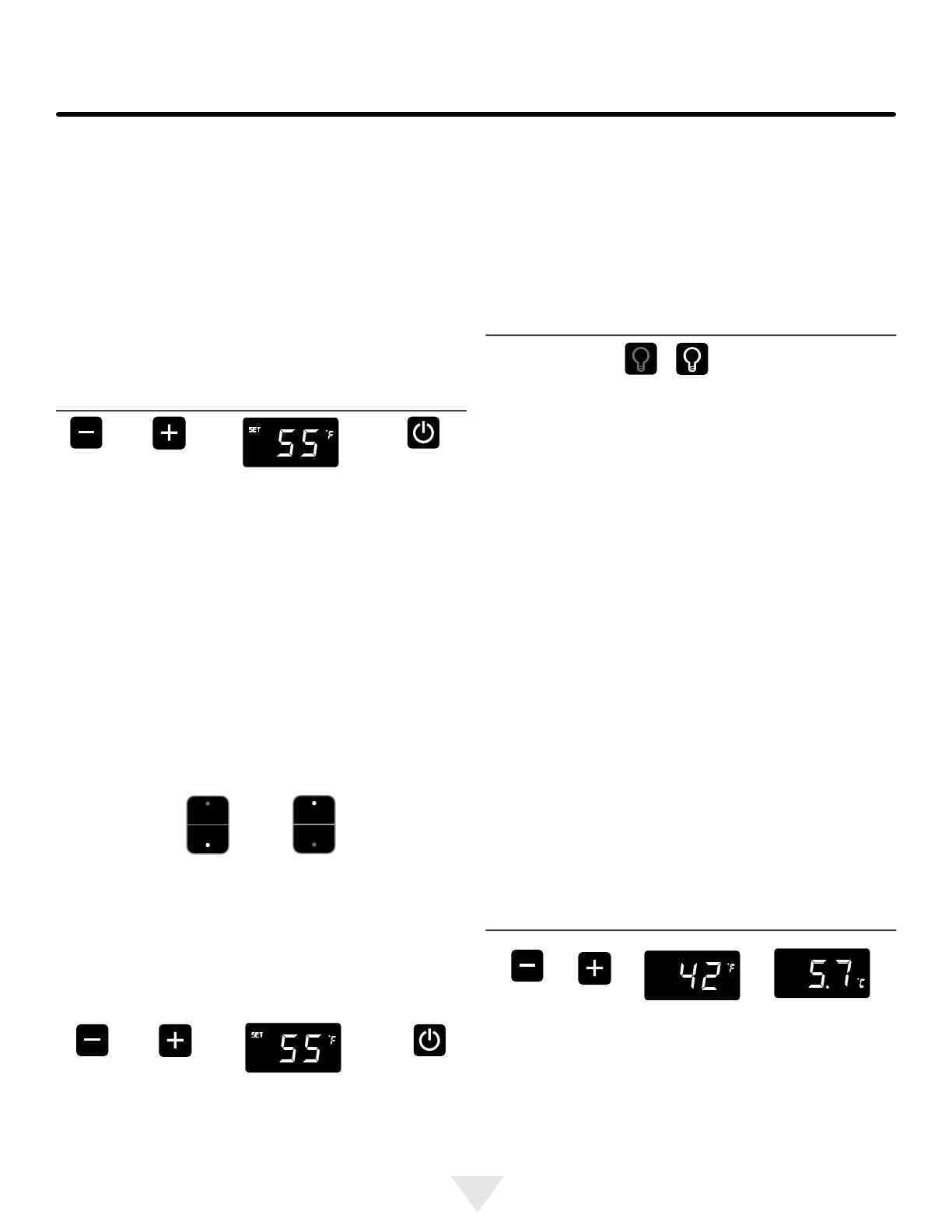
Temperature mode (Single and Dual Zone):
The temperature mode is preset from the factory in Fahren-
heit (°F) but you have the option to change it to Centigrade
(°C). To change the mode, press and hold the "-" keypad,
while pressing the "+" keypad, then release the "-" keypad.
The temperature will now be displayed in Centigrade (°C).
Repeat the procedure to change the temperature mode
back to Fahrenheit (°F).
To change the set temperature for a particular zone, with
the zone selected and out of sleep mode, press the "-" or
"+" keypads. "SET" will be indicated on the user interface
panel and the current set-point temperature will display
and ash. Subsequent presses of the "-" or "+" keypads
10
Door Ajar
ALARM RESET
Control lock (Single and Dual Zone):
The control panel can be locked to avoid unintentional
changes. To lock the control, press and hold the "Lock" key-
pad until the display reads "Loc" then immediately release
your nger from the keypad. The lock icon will ash 3-times
and then continuously illuminate. When the control panel is
locked, only the Lock keypad, System Status OK indicator
, and the Alarm indicator are active. To un-lock the control
panel, repeat this instruction until the display reads "nLc"
then immediately release your nger from the keypad.
Alarms (Single and Dual Zone):
The control will alert you to conditions that could adversely
affect the performance of the appliance.
Door ajar - If the door is open, or not closed prop-
erly, for more than 5-minutes the System Status OK
indicator will turn-off, the "Door Ajar" indicator will ash,
and a tone will sound every 60 seconds. Additionally,
an "ALARM RESET" indicator will be displayed below
the "On/Off" keypad.
USING YOUR ELECTRONIC CONTROL
NOTE
If the control lock is active (illuminated lock icon) the control
will have to be unlocked before using the keypad to reset
an alarm condition. See page 10 (Control Lock) for instruc-
tions for unlocking the control.
The temperature sensors are monitored continuously. Any
OPEN or SHORTED circuit condition will initiate an
ERROR CODE as listed below:
Temperature Sensor Error Codes
Sensor Displayed Code Error Description Action to Take
Single Zone
Temperature Sensor
Failed temperature sensor in the single
zone compartment. Can lead to unwant-
ed wine storage temperatures.
Call service to have the tem-
perature sensor replaced.
Defrost Sensor
Failed defrost temperature sensor.
Causes unit to not defrost properly and
can create large frost build-up. Can lead
to water damage to the unit and sur-
rounding oor.
Unplug the power cord imme-
diately and call service to have
the defrost sensor replaced.
Single Zone Models:
Dual Zone Models:
Temperature Sensor Error Codes
Sensor Displayed Code Error Description Action to Take
Upper Zone
Temperature Sensor
Failed temperature sensor in the upper
zone compartment. Can lead to unwant-
ed wine storage temperatures.
Call service to have the tem-
perature sensor replaced.
Lower Zone
Temperature Sensor
Failed temperature sensor in the lower
zone compartment. Can lead to unwant-
ed wine storage temperatures.
Call service to have the tem-
perature sensor replaced.
Defrost Sensor
Failed defrost temperature sensor.
Causes unit to not defrost properly and
can create large frost build-up. Can lead
to water damage to the unit and sur-
rounding oor.
Unplug the power cord imme-
diately and call service to have
the defrost sensor replaced.
Temperature Sensor Error Codes
This alarm condition can be reset by closing the door
or momentarily pressing the "On/Off" keypad, (i.e.-if
you are cleaning the storage compartment, etc.). The
alarm will recur in 5-minutes if the alarm condition
persists.
NOTE
The audible alarm can be muted, for each occurrence,
by pressing the lock keypad.
11
ALARM RESET
Power Failure
ALARM RESET
Temp
NOTE
Door Ajar
Temp
Power failure - If power to the appliance is inter-
rupted the System Status indicator will turn-off and
the "Power Failure" indicator will ash. Additionally, an
"ALARM RESET" indicator will be displayed below the
"On/Off" keypad. No audible tone will sound. This alarm
condition can be reset by momentarily pressing the
"On/Off" keypad. If this alarm occurs, it is recommend-
ed that you check the condition of any perishables,
even if the appliance is operating normally and the tem-
perature has recovered, as prolonged power outages
could result in excessive temperature excursions which
may spoil perishables.
Temperature alarm - If the storage compart-
ment temperature deviates excessively from your
set-point temperature for an extended period of time,
the "TEMP" indicator will ash, and an audible tone
will sound every 60 seconds. Additionally, an "ALARM
RESET" indicator will be displayed below the "ON/
OFF" keypad.
Multiple alarms are possible, i.e.- "Door Ajar" for a pro-
longed period may trigger a "Temp" alarm, in which case
both "Door Ajar" and "Temp" indicators will activate.
USING YOUR ELECTRONIC CONTROL
Vacation mode (Single and Dual Zone):
This operating mode can be used to save energy during
high cost energy periods, or when you won't be using your
appliance for an extended period of time by disabling the
lights, alarm tones, and keypad entry tones. Vacation mode
also serves as a Sabbath mode, disabling functions and
its controls in accordance with the weekly Sabbath and
religious holidays observed within the Orthodox Jewish
community. When used as Sabbath mode, you may open
or close the door at any time to access contents without
concern of directly turning on or off any lights, digital read-
outs, solenoids, fans, valves, compressor, icons, tones, or
alarms.
When activated, the display, alarm indicators and tones,
keypad touch tones, interior lights, and all options are dis-
abled. All keypad functions are disabled, with the exception
of the "On/Off" keypad which is required to exit Vacation-
mode. Storage compartment temperatures are monitored
and controlled at the settings prior to entering Vacation
mode.
To enter Vacation Mode (with the control out of sleep
mode), press and hold the "On/Off" keypad until the display
goes past "OFF" and reads "VAC". The display will ash
"VAC" 3-times to acknowledge your request, then will
display "VAC" continuously until Vacation mode is exited.
A power outage will not exit Vacation mode, exiting can
only be accomplished manually. To exit Vacation mode and
return to normal operation, press and hold the "On/Off"
keypad until the control displays the temperature.
NOTE
The audible alarm can be muted, for each occurrence, by
pressing the lock keypad.
This alarm condition can be reset by momentarily pressing
the "On/Off" keypad. If this alarm occurs it is recommended
that you check the condition of your stored contents, even
though the appliance is operating normally and the temper-
ature has recovered, as prolonged temperature excursions
could spoil perishables.
NOTE
NOTE
After a high temperature alarm condition, check all perish-
ables to ensure they are safe for consumption.
The temperature alarm may occur as a result of high usage
or introduction of warm contents to the storage compart-
ment. If the temperature alarm continues to occur, your unit
may require service.
12
!
WARNING
!
WARNING
!
CAUTION
OVERLAY DOOR PANEL INSTALLATION
!
WARNING
Use extreme caution with the articulated hinges. The
hinge is self closing and many pinch points exist prior
to built-in installation. Do not remove the cabinet "Z"
bracket from the top of the cabinet.
Loosen (do not remove ) these
2 phillips head screws on the
top and bottom hinges
If you purchased an overlay panel model, your unit is
equipped with articulated hinges to allow fully integrated
built-in installations. Custom panel thicknesses of
5
8" (15
mm) and
3
4" (18 mm) are accommodated.
It is important to use the factory provided grille that came
with the product to assure proper air ow is maintained
through the condenser. The use of a custom grille is not
recommended and will void the warranty.
Figure 11
Figure 11b
Bottom of
door
Figure 11a
"P" clamp
and screw
Wire connector
see Figure 12
Cabinet
"Z" Bracket
Overlay panel models are designed for use with built-
in installations only. Use in freestanding installations
could result in personal injury.
Step 1: Removing the Door
With a phillips screwdriver remove the screw and "P" clamp
from the bottom of the door near the hinge. See Figure 11b.
Disconnect the door wire harness by pressing and holding
down the locking tab on the wire connector and pulling the
connector apart. See Figure 12.
Open the door and loosen the screws holding the hinges to
the cabinet (2 at the top and 2 at the bottom hinge). Do not
remove the screws but loosen them enough so the hinges
can be slipped off of the screws when sliding the door to
the side.
With a helper, and being careful not to scratch the cabinet
or the door, slide the door to the side about
1
2 inch and
remove the hinges and door from the unit.
The articulated hinges have many pinch points. Care-
fully close / collapse the hinges as soon as the door is
removed from the cabinet.
13
Figure 13a
OVERLAY DOOR PANEL INSTALLATION
Step 2: Remove the door gasket
With the door laying on a at surface and starting at a
corner of the door remove the magnetic door gasket from
the interior side of the door, see Figure 13. Set the gasket
aside on a at surface.
There are 10 holes in the gasket retainer extrusions, (3 on
each side and 2 at the top and bottom which are used to
fasten the panel to the front of the door. The screws are
provided in the literature pack.
Figure 13
Overlay panel
ush with top
of door.
Holes in
gasket
retainer.
Magnetic Gasket
remove starting at a
corner, grasp and pull
away from the door.
Step 3: Cut and drill the overlay panel
Depending on your model cut the overlay door panel to the
dimensions shown in Figures 14 to 21.
Overlay panel to
be centered on
width of door.
Figure 12
Press and hold down this
tab on the wire connector
and pull the connector apart.
14
1
4" (6 mm)
radius is
permissible
1
5
32"
(2.9 cm)
1
5
32"
(2.9 cm)
Clearance for
screw head,
4 places
Figure 16
Right Hand Hinged
Door 15" (38.1 cm) wide
appliance
OVERLAY DOOR PANEL INSTALLATION
Figure 14
Left Hand Hinged Door
15" (38.1 cm) wide
appliance
Top of door
Clearance for
screw head,
4 places
Hinge side of door
Hinge side of door
Clearance
for hinge
2 places
14
3
4"
(37.5 cm)
1
4" (6 mm)
Deep
Clearance
for hinge
2 places
Figure 15
Left Hand Hinged Door
15" (38.1 cm) Wide Appliance
3
27
32"
(9.7 cm)
1
11
16"
(4.3 cm)
14
3
4"
(37.5 cm)
1
4" (6 mm)
Deep
1" (25.4 mm) diameter
counter bore
1
4" (6.4mm)
deep 4 places.
4
1
8"
(10.5 cm)
Minimum
3
1
8"
(7.9 cm)
Minimum
Figure 17
Right Hand Hinged Door
15" (38.1 cm) wide appliance
4
1
8"
(10.5 cm)
Minimum
1
1
2"
(3.8 cm)
typical
2"
(5.1 cm)
3
11
16"
(9.4 cm)
3
27
32"
(9.7 cm)
1
1
2"
(3.8 cm)
typical
1" (25.4 mm) diameter
counter bore
1
4" (6 mm)
deep 4 places.
2"
(5.1 cm)
3
11
16"
(9.4 cm)
3
1
8"
(7.9 cm)
Minimum
1
11
16"
(4.3 cm)
4
7
8"
(12.4 cm)
1
3
16"
(3 cm)
3
1
8"
(7.9 cm)
5"
(12.7 cm)
1
3
4"
(4.4 cm)
4
7
8"
(12.4 cm)
5"
(12.7 cm)
3
1
8"
(7.9 cm)
Minimum
1
3
4"
(4.4 cm)
30
11
32"
(77.1 cm)
1
4" (6 mm)
radius is
permissible
1
3
16"
(3 cm)
3
1
8"
(7.9 cm)
3
1
8"
(7.9 cm)
Minimum
30
11
32"
(77.1 cm)
This side
facing interior
This side
facing interior
15
!
CAUTION
1
3
16"
(3 cm)
1
5
32"
(2.9 cm)
Figure 18
Left Hand Hinged Door
24" (61 cm) wide appliance
Weight of overlay door panel
must not exceed 10 pounds
(4.5 kg) for a glass door model.
Figure 20
Right Hand Hinged Door
24" (61 cm) wide appliance
Clearance
for hinge
at top and
bottom
Clearance for
screw head,
4 places
Figure 19
Left Hand Hinged Door
24" (61 cm) wide appliance
Figure 21
Right Hand Hinged Door
24" (61 cm) wide appliance
Clearance for hinge
at top and bottom
Clearance for
screw head,
4 places
Hinge side of door
Top of door
Top of door
Hinge side of door
OVERLAY DOOR PANEL INSTALLATION
This side
facing interior
This side
facing interior
23
3
4"
(60.3 cm)
1
4"
(6 mm)
Deep
23
3
4"
(60.3 cm)
1
4"
(6 mm)
Deep
1" (2.5 cm) diameter
x
1
4" (6 mm) deep
4 places
1
1
2"
(3.8 cm)
typical
1
11
16"
(4.3 cm)
1" (2.5 cm) diameter
x
1
4" (6 mm) deep
4 places
4
7
8"
(12.4 cm)
3
1
8"
(7.9 cm)
2"
(5.1 cm)
3
11
16"
(9.4 cm)
3
11
16"
(9.4 cm)
1
1
2"
(3.8 cm)
typical
1
11
16"
(4.3 cm)
3
27
32"
(9.8 cm)
1
4" (6 mm)
radius is
permissible
14"
(35.6 cm)
1
3
16"
(3 cm)
3
1
8"
(7.9 cm)
30
11
32"
(77.1 cm)
30
11
32"
(77.1 cm)
3
1
8"
(7.9 cm)
4
1
8"
(10.5 cm)
3
1
8"
(7.9 cm)
1
3
4"
(4.4 cm)
3
1
8"
(7.9 cm)
2"
(5.1 cm)
4
1
8"
(10.5 cm)
1
4" (6 mm)
radius is
permissible
14"
(35.6 cm)
4
7
8"
(12.4 cm)
3
27
32"
(9.8 cm)
3
1
8"
(7.9 cm)
1
3
4"
(4.4 cm)
1
5
32"
(2.9 cm)
16
Counter bore
lock hole
on back side.
Figure 22a
#10 x
1
2"
screw
Figure 22
Hinge side of door
1
2" (13 mm) diameter
drill through door panel,
from other side (see
detail above)
13
16"
(20.5 mm) counter bore,
7
16" (11 mm) deep.
17
32"
(13.7 mm)
3
1
2"
(89 mm)
OVERLAY DOOR PANEL INSTALLATION
Step 5: Assemble lock parts
Two (2) lock extensions are provided with the lock. Use the
longer extension for
3
4" thick overlay panels and the shorter
one for
5
8" thick overlay panels. Assemble the lock exten-
sion, cam stop washer, spring washer, and set screw to the
lock as shown in Figure 23 and 24.
Install this lock assembly into the lock hole in the overlay
panel and secure with the retaining nut on the back side
with a 15 mm socket and ratchet. Make sure the key slot in
the front of the lock is vertical.
Step 6: Install lock cam
Attach the lock cam to the back of the lock assembly with
the phillips head screw provided. Orient the lock cam verti-
cally when installing on the lock.
Step 4: Assemble the panel to the door
The preferred method of attaching the panel to the door
is to clamp the panel to the door so it cannot move while
drilling the screw pilot holes. Use bar clamps or "C" clamps
with pads on the clamping surfaces that will not mar the
panel or the door. The custom overlay panel should be
ush with the top of the door and centered along the width
of the door. See Figure 13a. Drill holes through the gasket
extrusion using the 10 holes as pilot holes. Use the drill
size from the chart in Table "B", being careful not to drill
through the front surface of the panel. If the overlay panel is
thinner than
5
8" (16 mm) thick shorter screws will have to be
obtained. Fasten the panel to the door with the 10 screws
provided in the literature pack. (See Figure 22a). Remove
the clamps and replace the gasket in the gasket extrusion
channels of the door. Some force may be required to seat
the gasket into the channels. Be sure the gasket corners
are seated properly.
Material Type #10 Wood Screw
Hardwood
1
8" (3.2 mm) Diameter. Pilot Hole
Softwood
7
64 (2.8 mm) Diameter. Pilot Hole
Table B
17
SECTION A-A
SCALE 1 : 1
LOCK
NUT
BRASS EXTENSION
CAM
PHILLIPS SCREW
13/16 COUNTER
BORE 7/16 DEEP
1/2 HOLE
3/4 INCH
WOOD PANEL
SPRING WASHER
INNER
DOOR
Figure 23
Figure 24
Cam stop
washer
Spring
washer
Cam
Set screw
Lock
Key
Retainer
nut
Screw
Brass extension
(2 lengths provided
Step 8: Secure the cabinet
Use the #8 x
3
4" black screws from the literature pack to
secure the counter top to the cabinet top through the holes
in the cabinet "Z" bracket.
Step 7: Install the door
Carefully open the top and bottom hinges on the door being
careful as there are many pinch points. Place the hinges
over the 4 screws in the cabinet, 2 at the top and 2 at the
bottom and slide the door into position. Tighten the 4 hinge
screws with a phillips screwdriver. (See Figures 11 and
11a). Place wire harness from the grille and mount to the
bottom of the door with the screw and "P" clamp removed
in step 1. (See Figure 11b). Reconnect the wire harness,
(See Figure 12).
Cabinet
"Z" bracket
#8 x
3
4" black
screws
(3 places)
Figure 25
OVERLAY DOOR PANEL INSTALLATION
18
SHELVING CONFIGURATIONS
Shelving Congurations
Your Marvel Professional Series appliance is equipped with
full extension ball bearing shelf glides to provide maximum
access and visibility for the product stored on the shelving
arrangements listed below.
Dual Zone Wine Cellar:
24" (61 cm) Wide models:
Upper Zone: (3) 8 bottle wire racks
Lower Zone: (1) 8 bottle wire rack
(2) 4 bottle half-depth wire racks
Single Zone Wine Cellar:
24" (61 cm) Wide models:
(5) 8 bottle wire racks
(2) 4 bottle half-depth wire racks
Single Zone Wine Cellar:
15" (38.1 cm) Wide models:
(6) 4 bottle wire racks
Figure 26
Figure 28
Figure 27
19
SHELF REMOVAL AND INSTALLATION
Figure 29
Figure 29a
!
CAUTION
Never try to remove a loaded shelf, remove everything from
the shelf before removing. Use both hands when removing
the shelf.
To remove a shelf:
Extend the shelf out of the cabinet until it stops.
Unload the shelf (see Figure 29).
Depress the locking tabs on both sides of the shelf and pull
the shelf straight out (see Figure 29a). When the shelf is
removed, push the extended cabinet mounted shelf exten-
sions back into the cabinet.
To re-install a shelf:
Pull out the cabinet mounted shelf extensions to assist the
engagement with the wire rack shelf.
Insert the wire rack side track into the cabinet mounted
shelf extensions on both sides.
Push the wire rack completely into the cabinet to engage
the locking tabs.
Pull the shelf out, (unloaded), to verify the wire rack is
locked into the side rails. If the wire rack falls out, the lock-
ing tabs are not engaged; repeat the installation.
Load the shelf as required.
Locking tab
Remove the
wine from the
shelf to be
removed
20
The following suggestions will minimize the
cost of operating your refrigeration appliance.
1. Do not install your appliance next to a hot appliance
(cooker, dishwasher, etc.), heating air duct, or other
heat sources.
2. Install product out of direct sunlight.
3. Ensure the front grille vents at front of appliance be-
neath door are not obstructed and kept clean to allow
ventilation for the refrigeration system to expel heat.
4. Plug your appliance into a dedicated power circuit. (Not
shared with other appliances).
5. When initially loading your new product, or whenever
large quantities of warm contents are placed within
refrigerated storage compartment, minimize door
openings for the next 12 hours to allow contents to pull
down to compartment set temperature.
6. Maintaining a relatively full storage compartment will
require less appliance run time than an empty compart-
ment.
7. Ensure door closing is not obstructed by contents
stored in your appliance.
8. Allow hot items to reach room temperature before plac-
ing in product.
9. Minimize door openings and duration of door openings.
10. Use the warmest temperature control set temperature
that meets your personal preference and provides the
proper storage for your stored contents.
11. When on vacation or away from home for extended pe-
riods, set the appliance to warmest acceptable tem-
perature for the stored contents.
12. Set the control to the “off” position if cleaning the
appliance requires the door to be open for an extended
period of time.
13. For wine storage products:
When serving temperatures are not required,
return the compartment(s) set temperature to the
ideal red and white wine long term storage tem-
perature of 13°C / 55°F.
Front Grille
Be sure that nothing obstructs the required air ow open-
ings in front of the cabinet. At least once or twice a year,
brush or vacuum lint and dirt from the front grille area (see
page 4).
SHOCK HAZARD: Disconnect electrical power from the
appliance before cleaning with soap and water.
Cabinet
The painted cabinet can be washed with either a mild soap
and water and thoroughly rinsed with clear water. NEVER
use abrasive scouring cleaners.
Interior
Wash interior compartment with mild soap and water. Do
NOT use an abrasive cleaner, solvent, polish cleaner or
undiluted detergent.
Care of Appliance
1. Avoid leaning on the door, you may bend the door
hinges or tip the appliance.
2. Exercise caution when sweeping, vacuuming or mop-
ping near the front of the appliance. Damage to the
grille can occur.
3. Periodically clean the interior of the appliance as
needed.
4. Periodically check and/or clean the front grille as
needed.
In the Event of a Power Failure
If a power failure occurs, try to correct it as soon as pos-
sible. Minimize the number of door openings while the
power is off so as not to adversely affect the appliance's
temperature.
Light assembly replacement
All models use LED lamps to illuminate the interior of the
appliance. This component is very reliable, but should one
fail, contact a qualied service technician for replacement
of the LED.
CARE AND CLEANING AND ENERGY SAVING TIPS
!
CAUTION
  • Page 1 1
  • Page 2 2
  • Page 3 3
  • Page 4 4
  • Page 5 5
  • Page 6 6
  • Page 7 7
  • Page 8 8
  • Page 9 9
  • Page 10 10
  • Page 11 11
  • Page 12 12
  • Page 13 13
  • Page 14 14
  • Page 15 15
  • Page 16 16
  • Page 17 17
  • Page 18 18
  • Page 19 19
  • Page 20 20
  • Page 21 21
  • Page 22 22
  • Page 23 23
  • Page 24 24
  • Page 25 25
  • Page 26 26
  • Page 27 27
  • Page 28 28
  • Page 29 29
  • Page 30 30
  • Page 31 31
  • Page 32 32
  • Page 33 33
  • Page 34 34
  • Page 35 35
  • Page 36 36
  • Page 37 37
  • Page 38 38
  • Page 39 39
  • Page 40 40
  • Page 41 41
  • Page 42 42
  • Page 43 43
  • Page 44 44
  • Page 45 45
  • Page 46 46
  • Page 47 47
  • Page 48 48

Marvel MP15WS1F4RP Mode d'emploi

Catégorie
Boissons glacées
Taper
Mode d'emploi

dans d''autres langues