Marvel ML24WDF4RP Manuel utilisateur
- Catégorie
- Boissons glacées
- Taper
- Manuel utilisateur
Ce manuel convient également à

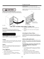
EN Installation, Operation and Maintenance Instructions
FR Instructions d’installation, d’utilisation et d’entretien
ES Instrucciones de instalación, operación y mantenimiento
Wine Refrigerator / Cooler
ML15WSG2**
ML15WSF3**
ML15WSP3**
ML24WSG3**
ML24WSF4**
ML24WSP4**
ML24WDG3**
ML24WDF4**
ML24WDP4**
Note: Wine refrigerators / coolers are designed exclusively
for the storage of wine. Wine refrigerators / coolers cannot
attain storage temperatures suitable for fresh food storage.

2
Remarque : Les celliers sont conçues exclusivement pour y
garder des vins. Elles ne peuvent pas atteindre des
températures de conservation convenant à l’entreposage
d’aliments frais.
Nota: Estas bodegas están diseñadas exclusivamente para
el almacenamiento de vino. Las bodegas para vinos no
pueden alcanzar las temperaturas adecuadas para el almacenamiento de alimentos frescos.
CONTENTS
Contents:
Safety information
...............................................................2 Unpacking your
appliance ..................................................3 Warranty
registration .....................................................3 Installing
your appliance ......................................................4
Cabinet clearances .........................................................4
Leveling the appliance ....................................................4
Electrical connection ......................................................5
Installing the anti-tip device
.................................................6 Product dimensions
............................................................8 Using your
Electronic control ............................................10 Starting
your appliance ..................................................10 Sleep
mode ...................................................................10
Turning your appliance "ON" or "OFF" ..........................10
Adjusting the temperature .............................................10
Interior display lighting ...................................................11
Temperature mode ........................................................11
Control lock ....................................................................12
Temperature sensor error codes .................................12
Alarms
...........................................................................12
Door ajar ..................................................................12
Power failure .............................................................13
Temperature alarm ....................................................13
Vacation mode ..............................................................13
Overlay door panel installation ........................................14
Shelving configurations
....................................................18 Care and cleaning
.............................................................20 Energy saving
tips ............................................................20 Obtaining
service .............................................................21
Troubleshooting
................................................................22 Warranty
...........................................................................23
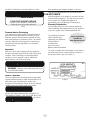
Important Safety Instructions
Warnings and safety instructions appearing in this guide
are not meant to cover all possible conditions and
situations that may occur. Common sense, caution, and
care must be exercised when installing, maintaining, or
operating this appliance.
Recognize Safety Symbols, Words,
and Labels.
CAUTION-Hazards or unsafe practices which could
result in personal injury or property / product damage.
NOTE-Important information to help assure a problem
free installation and operation.
! WARNING
State of California Proposition 65 Warning: This
product contains one or more chemicals known to
the State of California to cause cancer.
! WARNING
State of California Proposition 65 Warning: This
product contains one or more chemicals known to
!
CAUTION
!
WARNING
WARNING -
You can be killed or seriously injured
if you do not follow these instructions.
NOTE

3
the State of California to cause birth defects or other
reproductive harm..
! WARNING
EXCESSIVE WEIGHT HAZARD
Use two or more people to move product.
Failure to do so can result in personal
injury.
Remove Interior Packaging
Your appliance has been packed for shipment with all
parts that could be damaged by movement securely
fastened. Remove internal packing materials and any
tape holding internal components in place. The owners
manual is shipped inside the product in a plastic bag
along with the warranty registration card, and other
accessory items.
Important
Keep your carton and packaging until your appliance
has been thoroughly inspected and found to be in good
condition. If there is damage, the packaging will be
needed as proof of damage in transit. Afterwards
please dispose of all items responsibly.
This merchandise was carefully packed and thoroughly
inspected before leaving our plant. Responsibility for its
safe delivery was assumed by the retailer upon
acceptance of the shipment. Claims for loss or damage
sustained in transit must be made to the retailer.
DO NOT RETURN DAMAGED MERCHANDISE TO
THE MANUFACTURER - FILE THE CLAIM WITH THE
RETAILER.
If the appliance was shipped, handled, or stored in
other than an upright position for any period of time,
allow the appliance to sit upright for a period of at least
24 hours before plugging in. This will assure oil returns
to the compressor. Plugging the appliance in
immediately may cause damage to internal parts.
Warranty Registration
It is important you send in your warranty registration
card immediately after taking delivery of your appliance
or you can register online at www.agamarvel.com.
The following information
will be required when
registering your appliance.
Service Number
Serial Number
Date of Purchase
Dealer’s name and address
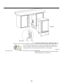
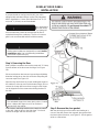
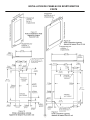
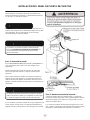
The service number and serial number can be found on
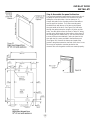
the serial plate which is located inside the cabinet on
the left side near the top. (See Figure 1).
Figure 1
UNPACKING YOUR APPLIANCE
!
WARNING
WARNING -
Dispose of the plastic bags which can
be a suffocation hazard.
Note to Customer
NOTE
XXXXXXXXXXXX
XXXXXXXXXXXX
!
CAUTION
Online registration
available at
www.agamarvel.com

4
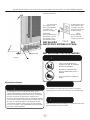
! WARNING
WARNING - Help Prevent Tragedies
Child entrapment and suffocation are not problems
of the past. Junked or abandoned refrigerators are
still dangerous - even if they sit out for "just a few
hours".
If you are getting rid of your old refrigerator, please
follow the instructions below to help prevent
accidents.
Before you throw away your old refrigerator or
freezer:
• Take off the doors or remove the drawers.
• Leave the shelves in place so children may not
easily climb inside.
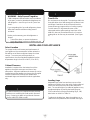
Select Location
The proper location will ensure peak performance of
your appliance. We recommend a location where the
unit will be out of direct sunlight and away from heat
sources. To ensure your product performs to
specifications, the recommended installation location
temperature range is from 55 to 100°F (13 to 38°C).
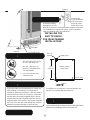
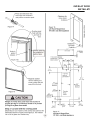
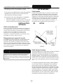
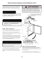
Cabinet Clearance
Ventilation is required from the bottom front of the
appliance. Keep this area open and clear of any
obstructions. Adjacent cabinets and counter top can be
installed around the appliance as long as the front grille
remains unobstructed. Overlay door models with
articulated hinges are intended for built-in applications
only.
! WARNING
An optional stacking kit is required to stack products.
Failure to use a stacking kit could result in personal
injury. Contact your dealer or Aga Marvel customer
service at 800-223-3900 to order.
Front Grille
Do not obstruct the front grille. The openings within the
front grille allow air to flow through the condenser heat
exchanger. Restrictions to this air flow will result in
increased energy usage and loss of cooling capacity.
For this reason it is important this area not be
obstructed and the grille openings kept clean. AGA
MARVEL does not recommend the use of a custom
made grille as air flow may be restricted. (See Figure
2).
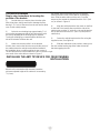
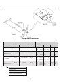
Leveling Legs
Adjustable legs at the front and rear corners of the
appliance should be set so the unit is firmly positioned
on the floor and level from side to side and front to
back. The overall height of your Marvel appliance may
be adjusted higher (by turning the leveling leg out,
CCW) and lower (by turning the leveling leg in, CW)
dimensions as shown in Table "A".
To adjust the leveling legs, place the appliance on a
solid surface and protect the floor beneath the legs to
INSTALLING YOUR APPLIANCE
!
CAUTION

5
avoid scratching the floor. With the assistance of
another person, lean the appliance back to access the
front leveling legs. Raise or lower the legs to the
required dimension by turning the legs. Repeat this
process for the rear by tilting the appliance forward
using caution. On a level surface check the appliance
for levelness and adjust accordingly.
The front grille screws may be loosened and the grille
adjusted to the desired height. When adjustment is
complete tighten the two front grille screws. (See Figure
5).
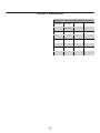
Model
Door Style
Minimum
Height
Maximum
Height
ML(15)(24)*
(S) or (G)
33
3
⁄4"
(85.7 cm)
34
3
⁄4"
(88.3 cm)
ML(15)(24)*
(P) or (F)
34"
(86.4 cm)
35"
(88.9 cm)
Table A
INSTALLING YOUR APPLIANCE
! WARNING
Electrical Shock Hazard
Do not remove • Do not use an extension cord with this appliance. ground prong They can be
hazardous and can degrade product
performance.
• This appliance should not, under any circumstances, be installed to an un-
grounded electrical supply.
• Do not remove the grounding prong from the power
cord. (See Figure 3).
Figure 3
• Do not use an adapter. See Figure 4).
• Do not splash or spray water from a hose on the appliance. Doing so may cause an electrical
shock, which may result in severe injury or death.
Electrical Connection
A grounded 115 volt, 15 amp dedicated circuit is required.
This product is factory equipped with a power supply cord that has a
three-pronged, grounded plug. It must be
Figure 4 plugged into a mating grounding type receptacle in accor-
dance with the National Electrical Code and applicable local codes and ordinances (see Figure 6). If the
circuit does not have a grounding type receptacle, it is the responsibility and obligation of the customer to
provide the proper power supply. The third ground prong should not, under any circumstances, be cut or
removed.

6
Figure 6
Ground Fault
Circuit Interrupters
(GFCI) are prone
to nuisance tripping which will cause
the appliance to shut down. GFCI’s are
generally not used on circuits with power equipment that must
run unattended for long periods of time, unless required to
meet local building codes and ordinances.
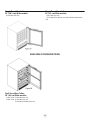
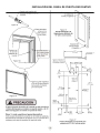
INSTALLING THE
ANTI TIP DEVICE
FOR FREESTANDING
INSTALLATIONS
! WARNING
If your wine cellar is not located under a counter top
(free standing), you must use an anti-tip device
installed as per these instructions. If the wine cellar is
removed from its location for any reason, make sure
that the device is properly engaged with the anti-tip
bracket when you push the wine cellar back into the
original location. If the device is not properly engaged,
there is a risk of the wine cellar tipping over, with the
potential for property damage or personal injury.
NOTE
If installing on a concrete floor, concrete fasteners are
required, (not included with the anti-tip kit).
Any finished flooring should be protected with appropriate
material to avoid damage when moving the unit.
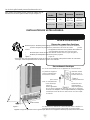
Front of cabinet
Figure 7
21
1
⁄
2
"
(54.6
cm
)
Anti-Tip
Bracket
Leveling Leg
Bottom View of
Wine Cellar
!
WARNING
•
ALL APPLIANCES CAN TIP
RESULTING IN INJURY.
•
INSTALL THE ANTI-TIP
BRACKET PACKED WITH
THE APPLIANCE.
•
FOLLOW THE INSTRUC
-
TIONS BELOW
Anti-Tip Device
!
CAUTION
Front grille
Front grille screw
Figure 5
NOTE

7
Floor Mount Installation
Step by step instructions for locating the
position of the bracket:
1) Decide where you want to place the wine cellar.
Slide it into place, being careful not to damage the floor,
leaving 1" (2.5 cm) of clearance from the rear wall to allow
room for the anti-tip bracket.
2) Raise the rear leveling legs approximately
1
⁄4" (6
mm) to allow engagement with the anti-tip bracket. Level
the unit by adjusting all the leveling legs as required.
Turning the leveling leg counterclockwise will raise the
unit and clockwise will lower the unit.
3) Make sure the wine cellar is in the desired
location, then mark on the floor the rear and side corner of
the cabinet where the anti-tip bracket will be installed. If
the installation does not allow marking the rear corner of
the cabinet, then make temporary lines on the floor
marking the front corner of the cabinet, excluding the
door. Slide the wine cellar out of the way. From the
temporary line extend the sidewall line back 21
1
⁄2" (54.6
cm) as shown in Figure 8.
4) Align the anti-tip bracket to the marks on the floor
so the side of the bracket lines up with the side of the
cabinet mark, and the "V" notches on the anti-tip bracket
line up with the end of the 21
1
⁄2" (54.6 cm) line (Rear of
cabinet line).
5) Fasten the anti-tip bracket to the floor using the
supplied screw. (See Figure 8).
6) Slide the cabinet back into position, making sure
the rear cabinet leveling leg slides under the anti-tip
bracket engaging the slot.
The anti-tip bracket is to be located on the floor in the left or right
rear corner of the wine cellar as shown in Figure 7.
INSTALLING THE ANTI TIP DEVICE FOR FREESTANDING
INSTALLATIONS
When the floor mounted anti-tip bracket is used the
minimum adjusted height of the cabinet is increased by
3
⁄8" (9 mm).
NOTE

8
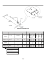
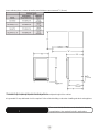
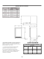
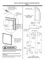
PRODUCT DIMENSIONS
ROUGH-IN OPENING DIMENSIONS
CABINET DIMENSIONS
MODEL
"A"
"B"
"C"
"D"
"E"
"F"
"G"
"H"
"J"
ML15WSG
15"
(38.1 cm)
**34" to 35"
(86.4 to 88.9 cm)
24"
(61 cm)
14
7
⁄8"
(37.8
cm)
33
3
⁄4" to
34
3
⁄4"
(85.7 to
88.3 cm)
23
23
⁄32"
(60.2
cm)
25
21
⁄32"
(65.2
cm)
37
13
⁄32"
(95 cm)
16
11
⁄16"
(42.4
cm)
ML15WS(P) or (F)
15"
(38.1 cm)
**34
1
⁄4" to 35
1
⁄4" (87 to 89.5
cm)
*24" (61
cm)
14
7
⁄8"
(37.8
cm)
34" to 35"
(86.4 to
88.9 cm)
22
7
⁄8"
(58.1
cm)
-
37
1
⁄2"
(95.2
cm)
14
1
⁄8"
35.9
cm)
ML24W*G
24"
(61 cm)
**34" to 35"
(86.4 to 88.9 cm)
24"
(61 cm)
23
7
⁄8"
(60.7
cm)
33
3
⁄4" to
34
3
⁄4"
(85.7 to
88.3 cm)
23
23
⁄32"
(60.2
cm)
25
21
⁄32"
(65.2
cm)
46
13
⁄32"
(117.9
cm)
25
11
⁄16"
(65.2
cm)
ML24W*(P) or (F)
24"
(61 cm)
**34
1
⁄4" to 35
1
⁄4" (87 to 89.5
cm)
*24" (61
cm)
23
7
⁄8"
(60.7
cm)
34" to 35"
(86.4 to
88.9 cm)
22
7
⁄8"
(58.1
cm)
-
46
1
⁄2"
(118.1
cm)
23
1
⁄8"
(58.7
cm)
DOOR STYLE
(G) Glass Frame Door
(P) Solid Overlay Door (no handle)
(F) Frame Glass Overlay Door (no handle)

9
opening a hole can be cut through the adjacent cabinet and the power cord routed through this hole
to a power outlet. Another way to increase the available opening depth is to
recess the power outlet into the rear wall to gain the thickness of the power
cord plug. Not all recessed outlet boxes will work for this applica-
Figure 10
tion as they are too narrow, but a recessed outlet box
equivalent to Arlington #DVFR1W is recommended
for this application, (see Figure 10).

10
PRODUCT DIMENSIONS
APPLIES TO THE FOLLOWING MARVEL MODELS
ML15WS
ML24WS
ML24WD

11
jacent cabinetry doors, custom decorative panel thickness cannot exceed
3
⁄4" (19 mm).
** Minimum rough-in opening required is to be larger than the adjusted height of the cabinet.
# A grounded 15 amp dedicated circuit is required. Follow all local building codes when installing electrical and appliance.
Floor mount Anti-tip Bracket must be installed for freestand-
! WARNING ing applications. Not required for built in applications.

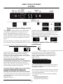
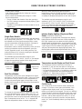
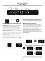
USING YOUR ELECTRONIC
CONTROL
12
Upper/Lower
Temp Temp zones Lights keypad
Plug the appliance power cord into a 115 volt wall outlet.
Your appliance is shipped from the factory in the "On"
position and will begin start-up of cooling as soon as
power is supplied. If the appliance does not start, confirm
that the wall outlet has power, and that the control is in the
"On" position, (See "Turning your appliance On and Off"
below).
The control display is covered with a clear plastic film. This
film may be removed by carefully lifting the film at a corner.
On initial power up, the control display will indicate a
"Power Failure" alarm. This is a normal condition as the
appliance was powered-up at the factory for quality
inspection and then removed from power. A momentary
press of the "On/Off" keypad will reset this alarm condition.
(See Alarms section on page 12).
The sleep mode can be disabled if you prefer to have the
display on continuously. Press and hold the "Lock" keypad
until the display goes past "Loc" and reads "nSL". To
enable the sleep mode, repeat the instruction, again going
past "Loc" until the display reads "SLP".
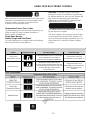
Turning your appliance ON and OFF (Single
and Dual Zone):
If the appliance is "On", (and out of sleep mode) the
temperature will be shown in the display area of the
control. To turn the appliance "Off", press and hold the
"On/Off" keypad for 4-seconds. "OFF" will now be
displayed on the
Sleep mode (Single and Dual Zone):
If no keypads are pressed for 60 seconds, the display will
enter sleep mode to conserve power. The control panel will
go dark with the exception of the system status "OK"
indicator which will remain enabled. Alarm conditions will
wake the display, (see alarms on page 12).
To make the following changes to the control settings
(turning the appliance ON/OFF, adjusting the
temperature, changing the interior lights, and
activating vacation mode), the control must be awake.
To wake the display press any keypad. A confirm tone will
sound, and the current storage compartment temperature
will be displayed.
keypad for 4-seconds.
Adjusting the temperature:
When initially loading your product with warm contents, it
may take up to 48-hours for the storage compartment
temperature to stabilize.
When making temperature set-point changes, it may take
up to 24-hours for the stored contents to stabilize at your
new set-point temperature.
Factors that affect the storage compartment stabilized
temperature:
• Changes to temperature setting.
• Room temperature changes.
• Temperature of stored contents.
NOTE
control.
To turn the appliance "On", press and hold the "On/Off"

USING YOUR ELECTRONIC CONTROL
13
- Loading warm contents.
- Cold content load will delay the change to a warmer
set-point temperature.
- Warm content load will delay the change to a colder
set-point temperature.
• Usage, (number and duration of the door openings).
• Use of the storage compartment display lighting, (glass
door product only).
• Installation of the appliance in direct sunlight or next to
a heat source.
To set or check the set-point temperature (with the control
out of sleep mode), press the "-" or "+" keypads. "SET" will
be indicated on the user interface panel and the current
set-point temperature will display and flash. Subsequent
presses of the "-" or "+" keypads will adjust the
temperature colder or warmer respectively. When you have
reached your desired set-point temperature, press the
"On/Off" keypad to accept, or do nothing and the "Set"
mode will timeout in 10-seconds accepting the displayed
temperature as the new set-point.
The available set-point temperature range for your
appliance is 40°F (4.5°C) to 65°F (18.4°C). If you attempt
to adjust the temperature outside of this range you will
receive an audible notification.
Dual Zone Models:
Temperatures can be set for each individual zone (upper
and lower) in the dual zone wine cellar. To do so you must
first select the zone you want to set the temperature for.
You do so by pressing the upper or lower button on the
display. When pressed the LED light will be illuminated for
the respective display.
To change the set temperature for a particular zone, with
the zone selected and out of sleep mode, press the "-" or
"+" keypads. "SET" will be indicated on the user interface
panel and the current set-point temperature will display and
flash. Subsequent presses of the "-" or "+" keypads will
adjust the temperature colder or warmer respectively.
When you have reached your desired set-point
temperature, press the "On/Off" keypad to accept, or do
nothing and the "Set" mode will time-out in 10-seconds
accepting the displayed temperature as the new set-point.
The available set-point temperature range for your
appliance is 45°F (7.3°C) to 55°F (12.9°C) for the lower
zone and 55°F (12.9°C) to 62°F (16.8°C) for the upper
zone. If you attempt to adjust the temperature outside of
these ranges you will receive an audible notification.
Interior display lighting (Single and Dual
Zone): (Glass door models only)
Your appliance is equipped with a dual light level display
lighting feature. With the control out of sleep mode press
the "Light" keypad once to activate the interior lighting
display feature at full illumination. A confirmation tone will
sound, and the light bulb "Icon" will illuminate. Pressing the
"Light" keypad a 2nd time will dim the lighting to 50%. A
3rd press will deactivate the display lighting feature. The
display lighting will automatically deactivate after 4-hours.
Temperature mode (Single and Dual Zone):
The temperature mode is preset from the factory in
Fahrenheit (°F) but you have the option to change it to
Centigrade (°C). To change the mode, press and hold the
"-" keypad, while pressing the "+" keypad, then release the
"-" keypad. The temperature will now be displayed in
Centigrade (°C). Repeat the procedure to change the
temperature mode back to Fahrenheit (°F).
Control lock:
The control panel can be locked to avoid unintentional
changes. To lock the control, press and hold the "Lock"
keypad until the display reads "Loc" then immediately
release your finger from the keypad. The lock icon will flash
3-times and then continuously illuminate. When the control
panel is locked, only the Lock keypad, System Status OK
indicator , and the Alarm indicator are active. To un-lock
the control panel, repeat this instruction until the display
reads "nLc", then immediately release your finger from the
keypad.
Single Zone Models:
Lower zone
selected
Upper zone
selected

USING YOUR ELECTRONIC CONTROL
14
If the control lock is active (illuminated lock icon) the control
will have to be unlocked before using the keypad to reset
an alarm condition. See page 12 (Control Lock) for
instructions for unlocking the control.
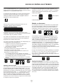
Temperature Sensor Error Codes
The temperature sensors are monitored continuously. Any
OPEN or SHORTED circuit condition will initiate an
ERROR CODE as listed below:
Single Zone Models:
Alarms (Single and Dual Zone):
The control will alert you to conditions that could adversely
affect the performance of the appliance.
• Door ajar - If the door is open, or not closed
properly, for more than 5-minutes the System Status
OK indicator will turn-off, the "Door Ajar" indicator will
flash, and a tone will sound every 60 seconds.
Additionally, an "ALARM RESET" indicator will be
displayed below the "On/Off" keypad.
The audible alarm can be muted, for each occurrence,
by pressing the lock keypad.
This alarm condition can be reset by closing the door
or momentarily pressing the "On/Off" keypad, (i.e.-if
you are cleaning the storage compartment, etc.). The
alarm will recur in 5-minutes if the alarm condition
persists.
Temperature Sensor Error Codes
Sensor
Displayed Code
Error Description
Action to Take
Single Zone
Temperature Sensor
Failed temperature sensor in the single
zone compartment. Can lead to
unwanted wine storage temperatures.
Call service to have the
temperature sensor replaced.
Defrost Sensor
Failed defrost temperature sensor.
Causes unit to not defrost properly and
can create large frost build-up. Can lead
to water damage to the unit and
surrounding floor.
Unplug the power cord
immediately and call service to
have the defrost sensor
replaced.
Dual Zone Models:
NOTE
Door Ajar
ALARM RESET
NOTE

USING YOUR ELECTRONIC CONTROL
15
• Power failure - If power to the appliance is
interrupted the System Status indicator will turn-off and
the "Power Failure" indicator will flash. Additionally, an
"ALARM RESET" indicator will be displayed below the
"On/Off" keypad. No audible tone will sound. This
alarm condition can be reset by momentarily pressing
the "On/Off" keypad. If this alarm occurs, it is
recommended that you check the condition of any
perishables, even if the appliance is operating normally
and the temperature has recovered, as prolonged
power outages could result in excessive temperature
excursions which may spoil perishables.
• Temperature alarm - If the storage compartment
temperature deviates excessively from your set-point
temperature for an extended period of time, the
"TEMP" indicator will flash, and an audible tone will
sound every 60 seconds. Additionally, an "ALARM
RESET" indicator will be displayed below the "ON/
OFF" keypad.
After a high temperature alarm condition, check all
perishables to ensure they are safe for consumption.
The temperature alarm may occur as a result of high usage
or introduction of warm contents to the storage
compartment. If the temperature alarm continues to occur,
your unit may require service.
The audible alarm can be muted, for each occurrence, by
pressing the lock keypad.
This alarm condition can be reset by momentarily pressing
the "On/Off" keypad. If this alarm occurs it is recommended
that you check the condition of your stored contents, even
though the appliance is operating normally and the
temperature has recovered, as prolonged temperature
excursions could spoil perishables.
Multiple alarms are possible, i.e.- "Door Ajar" for a
prolonged period may trigger a "Temp" alarm, in which
case both "Door Ajar" and "Temp" indicators will activate.
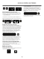
Vacation mode (Single and Dual Zone):
This operating mode can be used to save energy during
high cost energy periods, or when you won't be using your
appliance for an extended period of time by disabling the
lights, alarm tones, and keypad entry tones. Vacation
mode also serves as a Sabbath mode, disabling functions
and its controls in accordance with the weekly Sabbath and
religious holidays observed within the Orthodox Jewish
community. When used as Sabbath mode, you may open
or close the door at any time to access contents without
concern of directly turning on or off any lights, digital
readouts, solenoids, fans, valves, compressor, icons,
tones, or alarms.
When activated, the display, alarm indicators and tones,
keypad touch tones, interior lights, and all options are
disabled. All keypad functions are disabled, with the
exception of the "On/Off" keypad which is required to exit
Vacationmode. Storage compartment temperatures are
monitored and controlled at the settings prior to entering
Vacation mode.
To enter Vacation Mode (with the control out of sleep
mode), press and hold the "On/Off" keypad until the display
goes past "OFF" and reads "VAC". The display will flash
"VAC" 3-times to acknowledge your request, then will
display "VAC" continuously until Vacation mode is exited. A
power outage will not exit Vacation mode, exiting can only
be accomplished manually. To exit Vacation mode and
return to normal operation, press and hold the "On/Off"
keypad until the control displays the temperature.
ALARM RESET
Power Failure
ALARM RESET
Temp
NOTE
NOTE
NOTE
NOTE
Door Ajar
Temp

OVERLAY DOOR PANEL
INSTALLATION
16
If you purchased an overlay panel model, your unit is
equipped with articulated hinges to allow fully integrated
built-in installations. Custom panel thicknesses of
5
⁄8" (15
mm) and
3
⁄4" (18 mm) are accommodated.
It is important to
use the factory
provided grille
that came with the product to assure proper air flow is
maintained through the condenser. The use of a custom
grille is not recommended and will void the warranty.
! WARNING
Overlay panel models are designed for use with builtin
installations only. Use in freestanding installations
could result in personal injury.
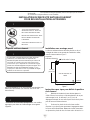
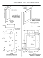
Step 1: Removing the Door
With a phillips screwdriver remove the screw and "P" clamp
from the bottom of the door near the hinge. See Figure
13b.
Disconnect the door wire harness by pressing and holding
down the locking tab on the wire connector and pulling the
connector apart. See Figure 14.
Open the door and loosen the screws holding the hinges to
the cabinet (2 at the top and 2 at the bottom hinge). Do not
remove the screws but loosen them enough so the hinges
can be slipped off of the screws when sliding the door to
the side.
! WARNING
The articulated hinges have many pinch points. Carefully
close / collapse the hinges as soon as the door is
removed from the cabinet.
With a helper, and being careful not to scratch the cabinet
or the door, slide the door to the side about
1
⁄2 inch and
remove the hinges and door from the unit.
Step 2: Remove the door gasket
With the door laying on a flat surface and starting at a
corner of the door remove the magnetic door gasket from
the interior side of the door, see Figure 15. Set the gasket
aside on a flat surface.
!
CAUTION

OVERLAY DOOR PANEL INSTALLATION
17
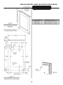
There are 10 holes in the gasket retainer extrusions, (3
on each side and 2 at the top and bottom which are used
to fasten the panel to the front of the door. The screws
are provided in the literature pack.

OVERLAY DOOR PANEL
INSTALLATION
18

OVERLAY DOOR PANEL
INSTALLATION
19
screw head,

OVERLAY DOOR PANEL
INSTALLATION
20
4 places
This side
facing
interior
1" (2.5 cm) diameter (9.4 cm)
x
1
⁄4" (6 mm) deep
4 places
La page est en cours de chargement...
La page est en cours de chargement...
La page est en cours de chargement...
La page est en cours de chargement...
La page est en cours de chargement...
La page est en cours de chargement...
La page est en cours de chargement...
La page est en cours de chargement...
La page est en cours de chargement...
La page est en cours de chargement...
La page est en cours de chargement...
La page est en cours de chargement...
La page est en cours de chargement...
La page est en cours de chargement...
La page est en cours de chargement...
La page est en cours de chargement...
La page est en cours de chargement...
La page est en cours de chargement...
La page est en cours de chargement...
La page est en cours de chargement...
La page est en cours de chargement...
La page est en cours de chargement...
La page est en cours de chargement...
La page est en cours de chargement...
La page est en cours de chargement...
La page est en cours de chargement...
La page est en cours de chargement...
La page est en cours de chargement...
La page est en cours de chargement...
La page est en cours de chargement...
La page est en cours de chargement...
La page est en cours de chargement...
La page est en cours de chargement...
La page est en cours de chargement...
La page est en cours de chargement...
La page est en cours de chargement...
La page est en cours de chargement...
La page est en cours de chargement...
La page est en cours de chargement...
La page est en cours de chargement...
La page est en cours de chargement...
La page est en cours de chargement...
La page est en cours de chargement...
La page est en cours de chargement...
La page est en cours de chargement...
La page est en cours de chargement...
La page est en cours de chargement...
La page est en cours de chargement...
La page est en cours de chargement...
La page est en cours de chargement...
La page est en cours de chargement...
La page est en cours de chargement...
La page est en cours de chargement...
La page est en cours de chargement...
La page est en cours de chargement...
La page est en cours de chargement...
La page est en cours de chargement...
La page est en cours de chargement...
La page est en cours de chargement...
La page est en cours de chargement...
La page est en cours de chargement...
La page est en cours de chargement...
La page est en cours de chargement...
La page est en cours de chargement...
La page est en cours de chargement...
La page est en cours de chargement...
La page est en cours de chargement...
La page est en cours de chargement...
La page est en cours de chargement...
La page est en cours de chargement...
La page est en cours de chargement...
La page est en cours de chargement...
La page est en cours de chargement...
-
 1
1
-
 2
2
-
 3
3
-
 4
4
-
 5
5
-
 6
6
-
 7
7
-
 8
8
-
 9
9
-
 10
10
-
 11
11
-
 12
12
-
 13
13
-
 14
14
-
 15
15
-
 16
16
-
 17
17
-
 18
18
-
 19
19
-
 20
20
-
 21
21
-
 22
22
-
 23
23
-
 24
24
-
 25
25
-
 26
26
-
 27
27
-
 28
28
-
 29
29
-
 30
30
-
 31
31
-
 32
32
-
 33
33
-
 34
34
-
 35
35
-
 36
36
-
 37
37
-
 38
38
-
 39
39
-
 40
40
-
 41
41
-
 42
42
-
 43
43
-
 44
44
-
 45
45
-
 46
46
-
 47
47
-
 48
48
-
 49
49
-
 50
50
-
 51
51
-
 52
52
-
 53
53
-
 54
54
-
 55
55
-
 56
56
-
 57
57
-
 58
58
-
 59
59
-
 60
60
-
 61
61
-
 62
62
-
 63
63
-
 64
64
-
 65
65
-
 66
66
-
 67
67
-
 68
68
-
 69
69
-
 70
70
-
 71
71
-
 72
72
-
 73
73
-
 74
74
-
 75
75
-
 76
76
-
 77
77
-
 78
78
-
 79
79
-
 80
80
-
 81
81
-
 82
82
-
 83
83
-
 84
84
-
 85
85
-
 86
86
-
 87
87
-
 88
88
-
 89
89
-
 90
90
-
 91
91
-
 92
92
-
 93
93


Marvel ML24WDF4RP Manuel utilisateur
- Catégorie
- Boissons glacées
- Taper
- Manuel utilisateur
- Ce manuel convient également à
dans d''autres langues
- English: Marvel ML24WDF4RP User manual
- español: Marvel ML24WDF4RP Manual de usuario
Documents connexes
-
Marvel MLWC224SG01A Mode d'emploi
-
Marvel ML24WDG3LS Mode d'emploi
-
-
Marvel MP15WS1F4RP Mode d'emploi
-
Marvel ML15CPS1RB Mode d'emploi
-
-
Marvel MP24WDG5RS Manuel utilisateur
-
Marvel MP15CLP2LP Mode d'emploi
-
Marvel ML24WBG1RS Le manuel du propriétaire
-