
UHF Wireless Systems
ESW-R210
UHF Synthesized Diversity Receiver
Installation and Operation

2
ESW-R210 UHF Synthesized Diversity Receiver
Installation and Operation
CAUTION! The circuits inside the receiver and transmitter
have been precisely adjusted for optimum performance and
compliance with federal regulations. Do not attempt to open
the receiver or transmitter. To do so will void the warranty, and
may cause improper operation.
Individuals with implanted cardiac pacemakers or AICD
devices: Please see notice on back cover.
This device complies with part 15 of the FCC Rules. Operation
is subject to the condition that this device does not cause
harmful interference.
This device complies with INDUSTRY CANADA R.S.S. 210, en
conformité avec IC: RSS-210/CNR210. Operation is subject to
the following conditions: 1) This device may not cause harmful
interference and 2) this device must accept any interference
received, including interference which may cause undesired
operation.
AVIS
RISQUE DE CHOC ÉLECTRIQUE
NE PAS OUVRIR
CAUTION
RISK OF ELECTRIC SHOCK
DO NOT OPEN
Warning: This apparatus must be grounded.
This product is a safety class 1 product.
There must be an uninterruptible safety earth
ground from the main power source to the
product‘s AC input. Whenever it is likely that
the protection has been impaired, disconnect
the power cord until the ground has been
restored.
Attention: Cet appareil doit être mise à la
terre. Cet appareil est de classe de sûreté 1.
Il doit y avoir un ininterrompable de mise à la
terre de sécurité provenant de la source
principale de courant de l‘appareil de l‘entrée
du courant alternatif. Quand la protection a été
affaiblie, débrancher le fil de courant jusqu‘à la
mise à terre a bien été réétablie.
Warning: To prevent fire or shock hazard, do
not expose this appliance to rain or moisture.
Attention: Pour prévenir feu ou choc
électrique, ne pas exposé l’appareil à la pluie
ou à l’humidité.
Caution/Avis: For continued protection
against fire hazard, replace only with same
type/rating of fuse.
Pour poursuivre la protection contre le feu,
replacez la fusible de même type/cote.
Warning/Attention: There are some sharp
edges inside. To reduce the risk of injury,
do not remove cover.
Bord tranchant à l‘intérieur. Pour réduire le
risque de blessure, ne pas ouvir le couvercle.
To prevent electric shock, do not remove the
cover. There are no user-serviceable parts
inside. Internal adjustments are for qualified
professionals only. Refer all servicing to
qualified service personnel.
Pour prévenir un choc électrique, ne pas ouvrir
le couvercle. Il n’y aucune pièces de rechanges
à l’intérieur. Tout ajustement interne doit être
fait par une personne qualifié seulement.
Référez tout réparation au personnel qualifié.
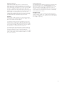
Location
For best operation the receiver should be at least 3 ft.
above the ground and at least 3 ft. away from a wall or
metal surface to minimize
reflections. The transmitter
should be at least 3 ft. from
the receiver, as shown in
Figure A.
Keep antennas away from
noise sources such as digital
equipment, motors,
automobiles and neon
lights, as well as large
metal objects.
Introduction
Audio-Technica Engineered Sound
®
wireless systems are
offered as separate receiver and transmitter units, rather
than in predetermined combinations, for greatest system
flexibility. Operating details for Engineered Sound transmit-
ters are included with each transmitter.
Engineered Sound receivers feature a sophisticated Tone
Lock
™
tone squelch system that opens only when an
Engineered Sound transmitter is detected, reducing the
possibility of interference. As a result, Engineered Sound
transmitters and receivers must be used together and
should not be used with components from other
Audio-Technica wireless systems, or with those of other
manufacturers.
The ESW-210 Receiver offers 100 PLL-synthesized UHF
frequencies and true diversity reception. Two antennas feed
two completely independent RF sections (Tuners) on the
same frequency. Automatic logic circuitry continuously
compares and selects the superior received signal,
providing better sound quality and reducing the possibility of
interference and dropouts. The ESW-R210 also provides
+12V DC on the antenna jacks to power in-line RF devices.
The receiver is housed in a full-width standard 19" (1U)
rack-mountable case, with rack-mount adapters included.
Please note that in multiple-system applications there must
be a transmitter-receiver pair set to a separate frequency for
each input desired (only one transmitter at a time for each
receiver). Because the wireless frequencies are on UHF TV
frequencies, only certain wireless frequencies may be use-
able in a particular geographic area. Also, only certain of the
available operating frequencies may be used together in
multi-channel systems. (Suggestions for multiple-frequency
groupings will be found on page 7.)
Fig. A
Receiver Installation

3
Output Connections
There are two audio output jacks on the back panel:
balanced (4 mV) and unbalanced (40 mV). Use shielded
audio cable for the connection between the receiver and the
mixer. If the input of the mixer is a
1
/
4
" jack, connect a cable
from the
1
/
4
" unbalanced audio output on the back of the
receiver housing to the mixer. If the input of the mixer is an
XLR-type input, connect a cable from the balanced XLR-type
audio output on the back panel to the mixer. The two
isolated audio outputs permit simultaneous feeds to both
unbalanced and balanced inputs. For example, both a tape
recorder and a mixer can be driven by the receiver.
Antennas
Attach a pair of UHF antennas to the antenna input jacks.
The antennas are normally positioned in the shape of a “V”
(45° from vertical) for best reception.
The antennas can be remotely located from the receiver.
However, due to signal loss in cables at UHF frequencies,
use the lowest-loss RF cable type(s) practical for any cable
runs over 25 feet. RG-8 is a good choice. Use only copper-
shielded cable, not CATV-type foil-shielded wire.
The antenna input jacks also provide +12V DC output on
their center pins to power in-line RF devices. Twenty (20)
mA can be drawn from each of the jacks. While an
accidental short-circuit will not harm the internal 12V supply,
make certain that an antenna cable shield does not contact
the center conductor.
Power Connections
The switching power supply is designed to operate properly
from any AC power source 120-240V, 50/60 Hz without
adjustment. Simply connect to a standard AC power outlet,
using an IEC input cordset approved for the country of
operation. Use the included cable clamp to secure the plug
in the chassis connector. Power to the unit is controlled by
the front-panel Power switch.
Headphone Jack
A headphone jack on the front panel provides monitoring
of the receiver’s output. The
1
/
4
" TRS jack is intended for use
with stereo headphones. The “Phones” level control affects
the headphone jack only.

4
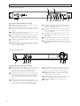
Receiver Controls And Functions
Fig. B Receiver Front Panel
Fig. C Receiver Rear Panel
1
2
3
4
6
7 8 9
10
5
11
12
13
14
15
16 17
18
15 UNBALANCED AUDIO OUTPUT JACK:
1
/
4
" phone
jack. Can be connected to an unbalanced aux-level
input of a mixer, guitar amp or tape recorder.
16 AC POWER: IEC-type connector for 120-240V AC
50/60 Hz power input. No adjustment for mains
voltage/frequency is necessary.
17 POWER CABLE CLAMP: Use provided cable clamp
to secure the plug in the chassis connector.
18 GROUND TERMINAL: Case grounding screw, if
needed.
Front Panel Controls and Functions (Fig. B)
1 POWER SWITCH: Press switch On and the Channel
Designator Display (5) will light.
2 AF LEVEL INDICATOR: Indicates the audio modulation
level of the received signal. The LEDs light up from left
to right.
3 RF LEVEL INDICATOR: Indicates the strength of the RF
signal received from the transmitter.
4 TUNER OPERATION INDICATOR: Indicates which Tuner
(A or B) has the better reception and is in operation.
Lights only when receiving an ES transmitter’s signal.
5 CHANNEL DESIGNATOR DISPLAY: Indicates the current
channel setting.
6 CHANNEL SET BUTTON: Hold this button in and press
“Up” or “Down” to change the channel shown in the
Channel Designator Display.
7 CHANNEL SELECTOR “DOWN” SWITCH: Changes
the channel designator, decreasing from 99 to 00.
“Rolls over” from 00 to 99.
8 CHANNEL SELECTOR “UP” SWITCH: Changes the
channel designator, increasing from 00 to 99. “Rolls
over” from 99 to 00.
9 “PHONES” LEVEL CONTROL: Adjusts the level of
the headphone jack only; it does not affect receiver
audio output.
10 HEADPHONE OUTPUT:
1
/
4
" TRS phone jack. Plug in
a “stereo” headphone to monitor receiver signal.
11 MOUNTING ADAPTERS: For mounting the receiver in
any standard 19" rack. Attach to receiver with screws
supplied.
12
Rear Panel Controls and Functions (Fig. C)
12 ANTENNA INPUT JACKS: BNC-type antenna connectors
for “A” and “B” Tuners. Attach antennas directly, or
extend them with low-loss antenna cable. See the
“Antennas” section on page 3 for more details.
13 GROUND LIFT SWITCH: Disconnects the ground pin
of the balanced output (14) from ground. Normally, the
switch should be to the right (ground connected). If
hum caused by a ground loop occurs, slide switch to
the left.
14 BALANCED AUDIO OUTPUT JACK: XLRM-type connec-
tor. A standard 2-conductor shielded cable can be used
to connect the receiver output to a balanced micro-
phone-level input on a mixer or integrated amplifier.

Turn down the mixer/amplifier level before starting up the
wireless system.
Switch on the receiver. Do
not
switch on the transmitter yet.
Receiver On…
The Channel Designator Display will light. If any of the RF
LEDs light up at this point, there may be RF interference in the
area. If this occurs, select another frequency using the front-
panel channel selectors. While holding in the “Set” button,
press the “Up” or “Down” button to access the desired
frequency; then release the Set button to select the channel.
Transmitter On…
Refer to the manual included with each Engineered Sound
transmitter for details of setup and operation.
Before turning on the transmitter,
make certain it is set to the
same operating channel as the receiver.
When the transmit-
ter is switched on and in normal operation, the
receiver’s RF signal level indicators will light up from left to
right. For optimum performance at least four, and preferably
five, of the signal strength indicators should light up when the
transmitter is switched on. One of the Tuner LEDs (A or B)
also will light up when the transmitter is on, indicating that its
signal has been received and the receiver’s Tone Lock squelch
circuit has opened.
Setting Levels
Although Engineered Sound receivers require no level
adjustment, correct adjustment of transmitter audio input
and mixer/amplifier input and output levels is important for
optimum system performance.
Engineered Sound transmitters include adjustments for
optimum audio modulation levels. Refer to the transmitter’s
manual for full details. Maximum audio input to the mic or
guitar should light about three or four green LEDs on the
receiver’s AF Level indicator. Audio modulation from the
transmitter level should not be allowed to light the red LED –
doing so will cause the system to overload and distort.
The audio output level of the ESW-R210 has been optimized
for best performance and no adjustment is necessary. The
level control on the front panel controls the headphone jack
only.
Receiver Squelch
The sophisticated Tone Lock system in ES wireless units
eliminates the need for any user-adjustable squelch control on
the receiver. Do not attempt to open the receiver housing or
adjust any internal alignment controls.
RF Interference
Please note that wireless frequencies are shared with other
radio services. According to Federal Communications
Commission regulations, “Wireless microphone operations are
unprotected from interference from other licensed operations
in the band. If any interference is received by any Government
or non-Government operation, the wireless microphone must
cease operation...”
If you need assistance with operation or frequency selection,
please contact your dealer or the Audio-Technica professional
division. Extensive wireless information also is available on the
Audio-Technica Web site at www.audio-technica.com.
5
System Operation
Ten Tips To Obtain The Best Results
1. Use only fresh alkaline batteries. Do not use “general
purpose” (carbon-zinc) batteries.
2. Position the receiver so that it has the fewest
possible obstructions between it and the normal
location of the transmitter. Line-of-sight is best.
3. The transmitter and the receiver should be as close
together as conveniently possible, but no closer
together than three feet.
4. The receiver antennas should be in the open and
away from any metal. If mounted in a rack, have the
unit on top, or use external/remote antennas.
5. Each transmitter/receiver pair must be set to the
same channel number.
6. A single receiver cannot receive signals from two
transmitters at the same time.
7. For best operation, all the RF Level LEDs should be
lit (maximize RF input); but only the first two or three
AF Level LEDs should be lit (don’t overmodulate).
8. You need to change channels 1) when a strong
interference signal is received, 2) when the channel
breaks down, or 3) during multiple-system operation
in order to select an interference-free channel.
9. In the UniPak transmitter, the “MT” or “GT” input
control not in use should be set to minimum.
10. Turn the transmitter off when not in use. Remove the
batteries if the transmitter is not to be used for a
period of time.

6
Specifications
†
Receiver Accessories
OVERALL SYSTEM
Operating Frequency UHF band, 728.125 to 740.500 MHz
Number of Channels 100 total
Frequency Stability ±0.005%, Phase Lock Loop
frequency control
Modulation Mode FM
Normal Deviation ±5 kHz
Tone Squelch Frequency 32.768 kHz
Operating Range 300' typical
Operating Temperature Range 41° F (5° C) to 113° F (45° C)
Frequency Response 100 Hz to 15 kHz
ESW-R210 RECEIVER
Receiving System Dual independent tuners, automatic
switching diversity
Image Rejection >100 dB
Signal-to-noise Ratio >107 dB (IEC-weighted at ±40 kHz
deviation)
Total Harmonic Distortion <1% (±5 kHz deviation at 1 kHz)
Sensitivity 18 dBµV (S/N 60 dB at ±5 kHz
deviation, IEC-weighted)
Intermediate Frequencies 54.25 MHz, 10.7 MHz
Audio Output
Unbalanced: 40 mV (at 1 kHz, ±5 kHz deviation,
1M ohm load)
Balanced: 4 mV (at 1 kHz, ±5 kHz deviation,
600 ohm load)
Output Connectors
Unbalanced:
1
/
4
" phone jack
Balanced: XLRM-type
Headphone Output 20 mW max. into 16 ohms
(at 1 kHz, ±5 kHz deviation)
Antenna Inputs BNC-type, 50 ohms
Antenna Power +12V DC on input jacks, 20 mA max.
from each jack
Power Supply 120-240V AC, 50/60 Hz, autoadjusting
Dimensions 16.93" (430.0 mm) W x 1.73"
(44.0 mm) H x 6.89" (175.0 mm) D
without antennas, power cable or
rack-mount adapters
Weight 5.5 lbs (2.5 kg)
Accessories Included Two flexible UHF antennas,
rack-mount adapters, power cable and
power cable clamp
† In the interest of standards development, A.T.U.S. offers full details on its test methods
to other industry professionals on request.
ATW-A20 Pair of UHF ground-plane antennas with
5
/
8
"-27 thread
for mounting to microphone stands, etc. Takes RF
cables with BNC connectors, not included.
ATW-D70 UHF (728-750 MHz) active unity-gain antenna
distribution system provides two “1-in, 4-out” RF
channels; connects a pair of antennas to as many as
four diversity receivers. Includes four DC interconnect
cables to power up to four receivers, eight RF output
cables and two rack-mount adapters. Mounts in a single
(1U) 19" rack space.
For future reference, please record your system information here (the serial number appears on the bottom of the
receiver):
Receiver
ESW-R210 Serial Number

7
Engineered Sound
®
UHF Wireless Operating Frequencies
Multi-channel Systems
Following are groupings of frequencies suggested for multi-channel wireless systems.
Group A: Channels 00, 02, 08, 15, 46, 50, 60 (or 62), 71, 76, 80, 93, 99
-or-
Group B: Channels 01, 03, 07, 25, 30, 41, 44, 56, 69, 76, 77, 86
For use where TV Channel 57 is operating:
Channels 50, 60 (or 62), 71, 76, 80, 93, 99 (from Group A)
-or-
Channels 56, 69, 76, 77, 86 (from Group B)
For use where TV Channel 58 is operating:
Channels 00, 02, 08, 15, 46, 99 (from Group A)
-or-
Channels 01, 03, 07, 25, 30, 41, 44 (from Group B)
For use where TV Channel 59 is operating:
Channels 00, 02, 08, 15, 46, 50, 60 (or 62), 71, 76, 80, 93 (from Group A)
-or-
Channels 01, 03, 07, 25, 30, 41, 44, 56, 69, 76, 77, 86 (All of Group B)
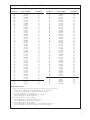
Designator Frequency (MHz) TV Channel
00 728.125 57
01 728.250 57
02 728.375 57
03 728.500 57
04 728.625 57
05 728.750 57
06 728.875 57
07 729.000 57
08 729.125 57
09 729.250 57
10 729.375 57
11 729.500 57
12 729.625 57
13 729.750 57
14 729.875 57
15 730.000 57
16 730.125 57
17 730.250 57
18 730.375 57
19 730.500 57
20 730.625 57
21 730.750 57
22 730.875 57
23 731.000 57
24 731.125 57
25 731.250 57
26 731.375 57
27 731.500 57
28 731.625 57
29 731.750 57
30 731.875 57
31 732.000 57
32 732.125 57
33 732.250 57
34 732.375 57
35 732.500 57
36 732.625 57
37 732.750 57
38 732.875 57
39 733.000 57
40 733.125 57
41 733.250 57
42 733.375 57
43 733.500 57
44 733.625 57
45 733.750 57
46 733.875 57
47 734.000 58
48 734.125 58
49 734.250 58
Designator Frequency (MHz) TV Channel
50 734.375 58
51 734.500 58
52 734.625 58
53 734.750 58
54 734.875 58
55 735.000 58
56 735.125 58
57 735.250 58
58 735.375 58
59 735.500 58
60 735.625 58
61 735.750 58
62 735.875 58
63 736.000 58
64 736.125 58
65 736.250 58
66 736.375 58
67 736.500 58
68 736.625 58
69 736.750 58
70 736.875 58
71 737.000 58
72 737.125 58
73 737.250 58
74 737.375 58
75 737.500 58
76 737.625 58
77 737.750 58
78 737.875 58
79 738.000 58
80 738.125 58
81 738.250 58
82 738.375 58
83 738.500 58
84 738.625 58
85 738.750 58
86 738.875 58
87 739.000 58
88 739.125 58
89 739.250 58
90 739.375 58
91 739.500 58
92 739.625 58
93 739.750 58
94 739.875 58
95 740.000 59
96 740.125 59
97 740.250 59
98 740.375 59
99 740.500 59
Frequency and Channel Designator List

Audio-Technica U.S., Inc., 1221 Commerce Drive, Stow, Ohio 44224 330/686-2600 www.audio-technica.com
P#2323-02461 P51248-B/W ©2000 Audio-Technica U.S., Inc. Printed in Japan
One-Year Limited Warranty
Audio-Technica professional wireless systems purchased in the U.S.A. are warranted for one year from date of purchase by Audio -Technica U.S., Inc.
(A.T.U.S.) to be free of defects in materials and workmanship. In event of such defect, product will be repaired promptly without charge or, at our
option, replaced with a new product of equal or superior value if delivered to A.T.U.S. or an Authorized Service Center, prepaid, together with the
sales slip or other proof of purchase date.
Prior approval from A.T.U.S. is required for return.
This warranty excludes defects due to normal wear,
abuse, shipping damage, or failure to use product in accordance with the instructions. This warranty is void in the event of unauthorized repair or
modification, or removal or defacing of the product labeling.
For return approval and shipping information,
contact the Service Dept., Audio-Technica U.S., Inc., 1221 Commerce Drive, Stow, Ohio 44224.
Except to the extent precluded by applicable state law,
A.T.U.S. will have no liability for any consequential, incidental, or special damages; any
warranty of merchantability or fitness for particular purpose expires when this warranty expires.
This warranty gives you specific legal rights, and you may have other rights which vary from state to state.
Outside the U.S.A., please contact your local dealer for warranty details.
Notice to individuals
with implanted cardiac pacemakers or AICD devices:
Any source of RF (radio frequency) energy
may
interfere with normal functioning of the implanted device. All wire-
less microphones have low-power transmitters (less than 0.05 watts output) which are unlikely to cause difficulty,
especially if they are at least a few inches away. However, since a “body-pack” mic transmitter typically is placed
against the body, we suggest attaching it at the belt, rather than in a shirt pocket where it may be immediately adjacent
to the medical device. Note also that
any medical-device disruption will cease when the RF transmitting source
is turned off
. Please contact your physician or medical-device provider if you have any questions, or experience any
problems with the use of this or any other RF equipment.
-
 1
1
-
 2
2
-
 3
3
-
 4
4
-
 5
5
-
 6
6
-
 7
7
-
 8
8


dans d''autres langues
Documents connexes
-
Audio Technica ESW-R220 Mode d'emploi
-
-
-
-
Audio Technica 700 Series Manuel utilisateur
-
-
-
-
-
Autres documents
-
Audio-Technica ATW-R1820 Manuel utilisateur
-
Samson AH1/QE Manuel utilisateur
-
Samson Technologies 77 Manuel utilisateur
-
-
-
-
-
TOA S4.4-RX-EAW Specification Data
-