Garland 36ER33-88 Owner Instruction Manual
- Catégorie
- Cuisinières
- Taper
- Owner Instruction Manual

Part # 4521653 Rev 1 (03/05/13) Page 1
Users are cautioned that maintenance and repairs must be performed by a Garland authorized service agent
using genuine Garland replacement parts. Garland will have no obligation with respect to any product that has been
improperly installed, adjusted, operated or not maintained in accordance with national and local codes or installation
instructions provided with the product, or any product that has its serial number defaced, obliterated or removed,
or which has been modified or repaired using unauthorized parts or by unauthorized service agents.
For a list of authorized service agents, please refer to the Garland web site at http://www.garland-group.com.
The information contained herein, (including design and parts specifications), may be superseded and is subject
to change without notice.
GARLAND COMMERCIAL RANGES LTD.
1177 Kamato Road
Mississauga, Ontario ,Canada L4W 1X4
Phone: 905-624-0260
Fax: 905-624-5669
General Inquires 1-95-624-0260
USA Sales, Parts and Service 1-800-424-2411
Canadian Sales 1-888-442-4526
Canada or USA Parts/Service 1-800-427-6668
Part # 4521653 Rev 1 (03/05/13) © 2005 Garland Commercial Industries, LLC
FOR YOUR SAFETY:
DO NOT STORE OR USE GASOLINE
OR OTHER FLAMMABLE VAPORS OR
LIQUIDS IN THE VICINITY OF
THIS OR ANY OTHER
APPLIANCE
WARNING:
IMPROPER INSTALLATION, ADJUSTMENT,
ALTERATION, SERVICE OR MAINTENANCE
CAN CAUSE PROPERTY DAMAGE, INJURY,
OR DEATH. READ THE INSTALLATION,
OPERATING AND MAINTENANCE
INSTRUCTIONS THOROUGHLY
BEFORE INSTALLING OR
SERVICING THIS EQUIPMENT
INSTALLATION & OPERATION MANUAL
GARLAND ED SERIES
ELECTRIC COUNTER UNITS
PLEASE READ ALL SECTIONS OF THIS MANUAL
AND RETAIN FOR FUTURE REFERENCE.
THIS PRODUCT HAS BEEN CERTIFIED AS
COMMERCIAL COOKING EQUIPMENT AND
MUST BE INSTALLED BY PROFESSIONAL
PERSONNEL AS SPECIFIED.
INSTALLATION AND ELECTRICAL CONNECTION
MUST COMPLY WITH CURRENT CODES:
IN CANADA - THE CANADIAN ELECTRICAL
CODE PART 1 AND / OR LOCAL CODES.
IN USA – THE NATIONAL ELECTRICAL CODE
ANSI / NFPA – CURRENT EDITION.
ENSURE ELECTRICAL SUPPLY CONFORMS WITH
ELECTRICAL CHARACTERISTICS SHOWN ON
THE RATING PLATE.

Part # 4521653 Rev 1 (03/05/13)Page 2
IMPORTANT INFORMATION
WARNING:
This product contains chemicals known to the state of california to cause cancer and/or birth defects
or other reproductive harm. Installation and servicing of this product could expose you to airborne
particles of glass wool/ceramic fibers. Inhalation of airborne particles of glass wool/ceramic fibers
is known to the state of California to cause cancer.

Part # 4521653 Rev 1 (03/05/13) Page 3
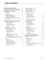
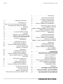
TABLE OF CONTENTS
IMPORTANT INFORMATION.............2
DIMENSIONS AND SPECIFICATIONS .....4
GENERAL INSTALLATION ...............5
Unpacking ...................................5
Serial Plate ..................................5
Statutory Regulations ........................5
Installation Of Banking Plates .................5
Sanitary Countertop Seal .....................5
Installation Of Counter Stands (Optional) ......6
Leg Installation ..............................6
INDIVIDUAL MODEL INSTALLATIONS ....7
Hot Plate – Model ED-15H ....................7
Wall Clearances .......................... 7
Supply Connection ....................... 7
Electrical Connection ..................... 7
Controls ................................. 7
Solid Elements Hot Plate –
Model ED-15HSE / ED-15THSE .................7
Wall Clearances .......................... 7
Supply Connection ....................... 7
Electrical Connection ..................... 7
Controls ................................. 7
Before Operating The Hot Plate ........... 7
Sealed Hot Plates......................... 7
Operating The Sealed Hot Plate ........... 8
Fryers – Models ED-15F, ED-15SF, ED-30FT & ED-
30SFT .......................................8
Wall Clearance ........................... 8
Supply Connection ....................... 8
Electrical Connection ..................... 8
Before Operating the Fryer ............... 8
Operating Suggestions ................... 8
Controls ................................. 9
Griddles – Models: ED-15G,
ED-24G & ED-36G
Grooved Griddles – Models:
ED-15G-U, ED-24-U,
ED-24G-U1, ED-36G-U,
ED-36-U1 & ED-36G-U2. . . . . . . . . . . . . . . . . . . . . . . 9
Wall Clearances .......................... 9
Supply Connection ....................... 9
Electrical Connection ..................... 9
Controls ................................. 9
Calibration Instructions ................... 9
Broilers – Models: ED-15B,
ED-30B & ED-42B ...........................10
Wall Clearance .......................... 10
Supply Connection ...................... 10
Electrical Connection .................... 10
Controls ................................ 10
Food Warmers –
Models ED-15W & ED-15WP ..................10
Wall Clearances ......................... 10
Supply Connection ...................... 10
Electrical Connection .................... 10
Controls ................................ 10
Operating Instructions................... 10
CLEANING AND MAINTENANCE ........11
Cleaning Exterior Finishes ...................11
Fryers ......................................11
Griddle Top Plates ...........................11
Seasoning............................... 11
Cleaning ............................... 11
Broiler .....................................11
Broiler Grates Surfaces................... 11
Broiler Interior and Under Broiler Grates .. 12
Periodic Cleaning........................ 12

Part # 4521653 Rev 1 (03/05/13)Page 4
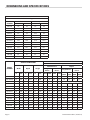
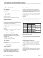
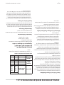
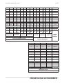
DIMENSIONS AND SPECIFICATIONS
LOADING AND VOLTAGE CHART
Total KW Loading
MODEL
NUMBER
North America Export
208V 240V 220V/380V 240V/415V
ED-15H 4.2 4.2 4.2 4.2
ED-15HSE 5.2 5.2 5.2 5.2
ED-15THSE 4.0 4.0 Contact Factory
ED-15F 5.3 5.3 5.93 5.3
ED-15SF 8.0 8.0 8.0 8.0
ED-30FT 10.6 10.6 11.86 10.3
ED-30SFT 16.0 16.0 16.0 16.0
ED-15G 3.4 3.4 3.4 3.4
ED-24G 6.7 6.7 6.7 6.7
ED-36G 10.1 10.1 10.1 10.1
ED-15B 2.7 2.7 2.7 2.7
ED-30B 5.4 5.4 5.4 5.4
ED-42B 8.1 8.1 8.1 8.1
ED-15W 1.0 1.0 1.12 1.0
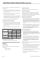
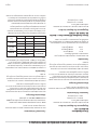
MODEL
NUMBER
OVERALL DIMENSIONS
PHASE AND AMPERAGE CHART
Nominal Amps Per Line
Width Depth Height
North America Export
Single
Phase
HI Line 3
Phase
Single Phase
Hi Line 2 0r 3
Phase
In mm in mm in mm 208V 240V 208V 240V
240V/
380V
240V/
425V
220V/
380V
240V/
415V
ED-15H 15 381 24 610 11.25 286 21 18 18 16 20 18 10 9
ED-15HSE 15 381 24 610 11.25 286 25 22 22 19 24 22 12 11
ED-15THSE 15 381 24 610 11.25 286 19.2 16.7 16.7 14.4 Contact Factory
ED-15F 15 382 24 610 13 330 26 23 N/A N/A 27 23 N/A N/A
ED-15SF 15 381 24 610 13 330 39 34 23 20 37 34 13 12
ED-30FT 30 762 24 610 13 330 51 45 45 39 54 45 27 22
ED-30SFT 30 762 24 610 13 330 77 67 45 39 73 67 25 23
ED-15G 15 381 24 610 13.75 349 17 14 N/A N/A 16 14 N/A N/A
ED-24G 24 620 24 610 13.75 349 33 28 28 25 31 28 16 14
ED-36G 36 914 24 610 13.75 249 49 42 28 25 46 42 16 14
ED-15B 15 381 24 610 13.75 349 13 12 N/A N/A 13 12 N/A N/A
ED-30B 30 762 24 610 13,75 349 26 23 23 20 37 34 13 12
ED-42B 42 1067 24 610 13.75 349 39 34 23 20 37 34 13 12
ED-15W 15 381 24 610 11.50 292 5 5 N/A N/A 6 5 N/A N/A

Part # 4521653 Rev 1 (03/05/13) Page 5
GENERAL INSTALLATION
Unpacking
Carefully remove units from cartons. Remove all packing
materials from units. The protective material covering the
stainless steel should be removed immediately after the unit
is installed.
Serial Plate
All electrical ratings are shown on the serial plate of each
unit and are readily visible by opening the enameled door
located below the control panel.
Ensure electrical supply conforms with electrical
characteristics shown on the rating plate.
Statutory Regulations
The installation and connection should comply with current
codes in Canada – The Canadian Electrical Code Part 1
and / or local codes. In USA – The National Electrical Code
ANSI / NFPA – Current Edition.
Ventilation requirements can vary by country, state or
providence, please consult with local authorities having
jurisdiction for code requirements.
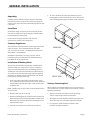
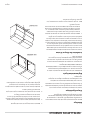
Installation Of Banking Plates
All units may be installed independently or banked with
other ED or GD series equipment. To ensure a matching
and permanent t between units, two banking plates are
available for each unit to be installed. One at the front and
one at the rear of each two units being banked together. If
optional 2 1/2” (64mm) legs are supplied with unit, discard
leveling bolts and replace with legs.
1. Level each unit by adjustment of leveling bolts or legs.
Use a spirit level and level unit four ways; across front and
back and down left and right edges. Level all other units
to the rst unit.
NOTE: Griddles may not rest evenly on the unit body if units
are not leveled.
2. Remove acorn nuts at rear of unit.
3. Attach one banking plate in position at rear by placing 1/4”
(6mm) diameter holes in the banking plate over the screw
holes in the rear of units and fasten by replacing the acorn
nuts removed in step 2.
4. Push units into position on counter top or back bar.
5. To secure the front, open the lower front panel, place
banking plate over the two holes (one on each unit) and
secure banking plate using sheet metal screws supplied.
REAR VIEW
FRONT VIEW
Sanitary Countertop Seal
When appliance is installed without legs on a counter top, it
must be sealed in accordance with N.S.F. standards as per the
following instructions:
1. Appliance should be located on a level counter top
surface. Complete the electrical connection.
2. Thoroughly clean the appliance bottom perimeter and
the counter top area around the appliance perimeter.
3. Lay a generous bead of silicone under the entire
perimeter of appliance bottom.

Part # 4521653 Rev 1 (03/05/13)Page 6
4. Secure unit to counter top through the holes located on
the underside of the appliance using 10A sheet metal
screws.
5. Smooth the silicone seal into the crevice with nger or
tool to provide a cove seal.
COUNTER TOP
SILICONE SEALANT
Installation Of Counter Stands (Optional)
1. Assemble and level counter stand as illustrated in the
instructions found in the counter stand carton.
2. Remove and discard leveling bolts on unit to be installed
on counter stand.
3. Place units in desired position on counter stand, securing
the rst unit with 8-32 machine screws and at washers.
Insert 8-32 machine screws through the 7/32” (5mm)
diameter holes in stand into the nutserts in the bottom of
ED Series unit.
4. Connect banking plates as described in section titled,
Installation of Banking Plates.
GENERAL INSTALLATION continued
5. Secure last unit to counter stand with 8-32 machine
screws and at washers. Inserts 8-32 machine screws
through the 7/32” (5mm) diameter holes in stand into the
nutserts in the bottom of ED series unit.
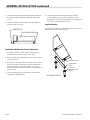
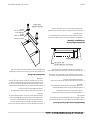
Leg Installation
The leg channel is located on the package base. This channel
must be installed when using the legs.
BOTTOM OF UNIT
LEG CHANNEL
(QTY 2)
4" [102mm]
ADJUSTABLE LEG
(QTY 4)
LEG INSTALLATION

Part # 4521653 Rev 1 (03/05/13) Page 7
INDIVIDUAL MODEL INSTALLATIONS
Hot Plate – Model ED-15H
Wall Clearances
Do not install appliance closer to a wall of combustible
material than:
Back 1 ½” (38mm)
Sides 1 ½” (38mm)
Supply Connection
For supply connection, use wire suitable for 90°C (194°F).
Electrical Connection
A knockout is provided near the front left side of the unit
located behind the control panel. To view knockout, loosen
the two acorn nuts and hinge control panel downward. The
terminal block is also located in this area.
The supply cable entrance is located on the right side when
facing the rear of the unit. The cable is fed towards the front
through a wire way.
Controls
Innite switches are used to control the tubular elements:
HI to 5 - High Heat
5 to 3 - Medium Heat
3 to LO - Low Heat
Setting of switches between the numbers will give
intermediate heat. Switches are reversible and may be
turned right or left.
Solid Elements Hot Plate –
Model ED-15HSE / ED-15THSE
Wall Clearances
Do not install appliance closer to a wall of combustible
material than:
Back 1 ½” (38mm)
Sides 1 ½” (38mm)
Supply Connection
For supply connection, use wire suitable for 75°C (167°F).
NOTE: - All 208V 1 phase 60 hZ ED-15THSE models are
equipped with a 4-ft (1219mm) power cord and
NEMA L6-30P plug (HUBBELL HBL2621 or equivalent).
Electrical Connection
A knockout is provided near the front left side of the unit
located behind the control panel. To view knockout, loosen
the two acorn nuts and hinge control panel downward. The
terminal block is also located in this area.
The supply cable entrance is located on the right side when
facing the rear of the unit. The cable is fed towards the front
through a wire way.
Controls
Solid element hot plates are controlled by a six heat switch.
There are three boiling and three simmering positions. Turn
the switch left or right from the o position to the desired
number, one being the lowest setting and six being the
highest.
SWITCH
POSITION
WATTAGE
HEAT
15HSE 15THSE
1 240 200
Low (Simmer)
2 340 305
3 450 450
Medium
4 1300 950
5 1750 1400
High (Boil)
6 2600 2000
This hot plate is protected against overheating when running
empty or when using poor quality cookware, by a unique
built-in bimetal protector switch.
This protector cuts down the power automatically under the
above conditions, overriding the regular switch and it resets
itself when conditions return to normal. This is an important
safety feature.
Before Operating The Hot Plate
The top working surface has a heat resistant coating. Before
using the sealed hot plates for the rst time, they should
be heated for a short period without a pan to harden and
burn o the protective coating (3-5 minutes at the highest
setting).
Sealed Hot Plates
All purpose sealed top elements provide an ease-clean top.
They are intended for boiling, simmering, sauté and other
top cooking.

Part # 4521653 Rev 1 (03/05/13)Page 8
Operating practices are very important for the ecient use of
these elements:
1. Pot bottoms must be at. This increases heat transfer to
the pot. Do not use pots with either convex or concave in
excess of 1mm (1/32”).
2. Use pots with the same diameter as the elements when
possible. This will reduce heat up time.
3. Do not preheat the element. Elements are protected with
a high limit which automatically reduces the element to a
lower power. It will increase heat up time if this occurs.
4. Use a lid to cover the pots when boiling water.
Operating The Sealed Hot Plate
1. Before using the sealed hot plates for the rst time they
should be heated at setting 3 for 5 minutes, then turned
o and allowed to cool. This will harden and burn o the
protective coating.
2. Set the six heat switch dial to the desired position from 1
to 6.
APPLICATION
DIAL
SETTING
WATTAGE
ED-15HSE ED-15THSE
Boiling, Frying,
Braising
6 2300 2000
5 1750 1400
4 1300 950
Simmering
3 450 450
2 340 305
Warming 1 240 200
Shutting down the sealed hot plate:
1. Turn the six heat switch to the o “O” position.
Fryers – Models ED-15F, ED-15SF, ED-30FT &
ED-30SFT
Wall Clearance
Do not install appliance closer to a wall of combustible
material than:
Back 1/2” (13mm)
Sides 1/2” (13mm)
INDIVIDUAL MODEL INSTALLATIONS continued
Supply Connection
For supply connection, use wire suitable for 75°C (167°F).
Electrical Connection
A knockout is provided on the right side when facing the
rear of the unit. Access to the terminal block is gained by
removing the fry tank assembly, the rear shield and contactor
box cover all located at the rear of the fryer.
Before Operating the Fryer
1. Before leaving the factory, the fryer was tested and the
thermostat calibrated with oil in the fry tank; therefore, it
is necessary to clean the fry tank and the elements before
lling with frying compound. Use detergent or other
cleaning agents, with hot water. Thoroughly rinse and dry
fry tank.
2. To remove the fry tank, raise the element assembly by
means of the handle until the support engages, holding
the element assembly in the upright position. The
element assembly is lowered by moving the lock stop to
release unit from upright position.
Operating Suggestions
1. For liquid oil ll the frypot with oil to the bottom OIL
LEVEL line located on the rear of the frypot. This allows
for oil expansion as heat is applied. Do not ll cold oil any
higher than the bottom line; overow may occur as heat
expands the oil.
2. When using a solid frying compound, pack the tank
with the compound then turn the fryer on and o every
10 seconds and repack until compound has melted.
The fryer capacity is 17 Lbs. (7.7Kg) per tank. Scorched
shortening cuts down on the useable life and could
damage the fryer.
CAUTION: Never set a complete block of solid shortening on
top of heating elements.
3. Ensure that the oil level is at the top OIL LEVEL line when
the oil is at its cooking temperature. It may be necessary
to add oil or shortening to bring the levels up to the
proper mark, after reaching cooking temperature.
4. To prolong shortening life, avoid over heating and reduce
the temperature during idle periods.
5. Ensure shorting is up to frying temperature before
adding foods.

Part # 4521653 Rev 1 (03/05/13) Page 9
6. To increase the life of the shortening, it should be ltered
with Garland fryer lter cones daily or more often, if
necessary.
7. Baskets should never be more than half full.
8. Keep fat at operating level.
9. Fry pieces of similar size at the same time for best results.
10. Excessive moisture should be shaken from the product
before frying.
11. Your shortening manufacturer can supply excellent frying
and shortening guides.
Controls
1. All ED series fryers are equipped with a manually
resettable high limit located at the rear of the element
termination box. In the event that shortening
temperatures exceed normal limits, the high limit will trip
and can only be reset by pushing the red button when
shortening has cooled.
2. All ED series are equipped with a precision electronic
thermostat which has been factory calibrated and is
designed to hold that calibration. There should never be
the need to calibrate this thermostat in the eld. Should
there ever be an abnormal discrepancy in the set point
of actual temperatures, or repeated tripping on the high
limit occurs, the fryer should be serviced by an authorized
Garland service agency.
Griddles – Models: ED-15G,
ED-24G & ED-36G
Grooved Griddles – Models:
ED-15G-U, ED-24-U,
ED-24G-U1, ED-36G-U,
ED-36-U1 & ED-36G-U2
Wall Clearances
Do not install appliance closer to a wall of combustible
material than:
Back 1 1/2” (38mm)
Sides 1” (25mm)
Supply Connection
For supply connection, use wire suitable for 75°C (167°F).
INDIVIDUAL MODEL INSTALLATIONS continued
Electrical Connection
A knockout is provided near the front left side of the unit
located behind the control panel. To view knockout, loosen
the two acorn nuts and hinge control panel downward. The
terminal block is also located in this area.
The supply cable entrance is located on the right side when
facing the rear of the unit. The cable is fed towards the front
through a wire way.
Controls
Griddles are equipped with snap action thermostats.
Calibration Instructions
1. Field calibration is seldom necessary and should not
be attempted unless experience with cooking results
denitely proves that the control is not maintaining the
temperature to which the dial is set.
2. Should calibration be required, use a test instrument
(pyrometer) which special disc type thermocouple or
reliable “surface” type thermometer.
NOTE: A drop of oil on face of disc will provide better
contact.
3. Turn ALL griddle temperature control dials to 350°F
(177°C). In order to allow griddle temperature to stabilize,
the controls must be allowed to cycle twice before taking
a test reading.
4. Check temperature reading when control just cycles
“OFF” (as indicated by the cycling amber pilot), by placing
sensor rmly on griddle surface directly above sensing
bulb of control. If the temperature does not read within
15°F (8°C) of the dial setting recalibrate as follows.
5. Carefully remove the thermostat dial making sure the
setting is not disturbed.
6. Hold dial shaft steady and with a screwdriver, turn
calibration screw located inside the dial shaft, clockwise
to decrease and counterclockwise to increase the
temperature.
EXAMPLE: 1/4 turn = 35°F (19°C)
7. Replace thermostat dial and repeat steps 2 through 4 to
verify correct adjustment has been made.

Part # 4521653 Rev 1 (03/05/13)Page 10
Broilers – Models: ED-15B,
ED-30B & ED-42B
Wall Clearance
Do not install appliance closer to a wall of combustible
material than:
Back 9” (229mm)
Sides 9” (229mm)
Supply Connection
For supply connection, use wire suitable for 90°C (194°F).
Electrical Connection
A knockout is provided near the front left side of the unit
located behind the control panel. To view knockout, loosen
the two acorn nuts and hinge control panel downward. The
terminal block is also located in this area.
The cable entrance is located on the right side when facing
the rear of the unit. The cable is fed towards the front
through a wire way.
Controls
Innite switches are used to control the elements.
HI to 5 - High heat
5 to 3 - Medium Heat
3 to LO - Low Heat
Setting of switches between the numbers will give
intermediate heat. Switches are reversible and may be
turned right or left.
Food Warmers – Models ED-15W & ED-15WP
Wall Clearances
Do not install appliance closer to a wall of combustible
material than:
Back 1” (25mm)
Sides 1” (25mm)
Supply Connection
NOTE: Applicable to Model ED-15W only. Model
ED-15WP is a 115 volt unit supplied with a grounded cord
and plug.
For Model ED-15W, use a wire suitable for 90°C (194°F).
Electrical Connection
NOTE: Applicable to Model ED-15W only.
A knockout is provided near the front left side of the unit
located behind the control panel. To view knockout, loosen
the two acorn nuts and hinge control panel downward. The
terminal block is also located in this area.
The supply cable entrance is located on the right side when
facing the rear of the unit. The cable is fed towards the front
through a wire way.
Controls
Innite switches are used to control the elements.
HI to 5 - High Heat
5 to 3 - Medium Heat
3 to LO - Low Heat
Setting of switches between the numbers will give
intermediate heat. Switches are reversible and may be
turned right or left.
Operating Instructions
ED series food warmers are supplied with a removable tank
assembly. Fill tank with 1-1/4” (32mm) to 1-1/2” (38,mm) of
water.
While not supplied with the food warmer it uses a 200
series of Gastronorm cafeteria pan and any arrangement
of 200 series pans in various sizes may be used. Individual
preference of the operation will determine sizes of inserts
to be used. Pans may be purchased from your kitchen
equipment dealer.
CAUTION: Do Not Allow The Tank Assembly To Run Dry.
ED Series food warmers are wet type only. Operating these
units dry for extended periods may cause the tank assembly
to warp and void the warranty.
INDIVIDUAL MODEL INSTALLATIONS continued

Part # 4521653 Rev 1 (03/05/13) Page 11
CLEANING AND MAINTENANCE
Cleaning Exterior Finishes
Black Baked Enamel – Allow equipment to cool after use
and wash all grease deposits from exterior with a hot mild
detergent or soap solution. Dry thoroughly. Do not use
abrasives.
Brushed Chrome Or Brushed Nickel – Wash when cool with
a hot mild detergent or soap solution. Do not use abrasives.
Stainless Steel – Normal soil may be removed with a
detergent or soap solution applied with a cloth.
To remove grease that has baked on, apply cleanser to a
damp cloth or sponge and rub cleanser on the metal in
the direction of the polishing lines of the metal. Never rub
in circular motion. Soil and brunt deposits, which do not
respond, can usually be removed by rubbing the surface with
Scotch-Brite scouring pads or stainless scouring pads. DO
NOT USE ORDINARY STEEL WOOL.
Heat tint can be removed by vigorous scouring in the
direction of the polish lines using Scotch-Brite scouring pads
or stainless scouring pad in combination with powdered
cleanser.
Exterior surfaces should be cleaned daily before debris is
allowed to heat and bake onto the surfaces.
Fryers
Cleaning The Fry Tank
1. If a liquid frying compound is used, allow the compound
to cool, then raise the element assembly by means of the
handle until the support engages and let the oil run o
the elements into the fry tank. Wipe the surface oil o the
elements to prevent dripping into the unit bottom when
the tank is removed. Lift out the fry tank and empty the
oil into a lter, after ltering it is then ready for re-use.
Clean the tank in the pot wash area with a mild detergent
and hot water. Rinse with a sponge dipped in a vinegar
and water solution. (3/4 cup of vinegar to 1 quart of
water) and dry thoroughly with a clean cloth.
2. If hydrogenated (solid) frying compound is used that has
been allowed to cool and become solidied, rst turn the
thermostat dial to 121°C (250°F) until the compound is
in a liquid state. Turn the thermostat dial/s to o “O”. Lift
the element assembly by means of the handle until the
support engages and let the oil run o the elements into
the fry tank. Then proceed as described in step 1 to lter
the compound and clean the fry tank.
3. Clean the top of the unit with a cloth soaked in a mild
detergent and hot water, including the front of the
element assembly housing. Rinse with a clean cloth
dipped in clean hot water, Dry thoroughly with a clean
cloth.
Griddle Top Plates
Seasoning
Before being used for the rst time, all the griddle surfaces
must be seasoned.
1. Wash griddle with a hot detergent or soap solution, rinse
and dry thoroughly.
2, Set the griddle heat to lowest possible temperature for 30
minutes. Apply a thin lm of cooking oil.
3. Allow oil to remain on griddle 5 minutes then wipe o.
4. Reset heat to medium temperature and apply a second
lm of oil.
5. Wipe o excess after 5 minutes. Reset heat to cooking
temperature and apply a nal lm of oil wiping o
surplus after 3 minutes.
The griddle is now seasoned and ready for use. The griddle
may be re-seasoned at any time by cleaning thoroughly and
following the seasoning procedure.
Cleaning
Griddle plates should be wiped daily while still warm.
Remove carbonized grease or food with spatula. When
necessary, clean griddle surfaces thoroughly using a ne
griddle brick or a liquid griddle cleaner (available from your
kitchen equipment dealer). Polish the griddle surface to a
bright nish. For stubborn residue wash the griddle surfaces,
rinse and dry thoroughly. Re-season griddle.
Broiler
Broiler Grates Surfaces
Broiler grates – or cooking racks are manufacture from a
cast iron material. For maximum eciency the racks should
be scraped and wiped down daily. Grease and other food
particles char and carbonize onto the rack surfaces building
up becoming harder to clean.

Part # 4521653 Rev 1 (03/05/13)Page 12
Broiler Interior and Under Broiler Grates
Debris and grease that gathers inside the broiler and must be
removed.
Daily
1. Lowering the front black enamel panel and remove the
grease drawer to be empty. NEVER operate the broiler
without the grease drawer. A magnetic door catch on
the grease drawer holds the front panel closed, acting as
a simple safety reminder. The front panel will not close
when the grease drawer is not in place.
2 In order for an electric broiler to heat up the cooking
racks/grates the electric elements must be attached
to the grates. After the broiler has cooled down, clean
inside the broiler under these grates using the broiler
grate lifter supplied with the broiler to lift the racks. Once
the grates are lifted a prop will kick out that is attached to
the underside of the grates to hold assembly up. This will
allow you access to clean the inside the broiler.
CLEANING AND MAINTENANCE continued
Periodic Cleaning
Over time debris carbonizes on the broiler grates requiring
major cleaning with detergent soap or degrease agent. The
broiler racks can be completely removed from the attached
elements for cleaning.
WARNING: All power should be shut o prior to cleaning.
1. Lift the broiler grates as described in the daily cleaning
section.
2 You will see the elements clamps that attaches the
elements to grates. Remove the element clamps and
clean the broiler racks.
3. Reverse the above procedure to reassemble the broiler.
After major cleaning it is recommended that you re-season
the broiler grates. Broiler grates are manufactured from cast
iron, which is a porous material. Major cleaning removes the
oils in the metal that helps prevent food from sticking to the
cook surface requiring re-seasoning.
To re-season the grates heat the broiler at a low temperature
setting then rub cooking oil into the broiler rack. At this point
you are ready to begin cooking again. If food is still sticking
to the broiler grate rub more cooking oil onto the grates.
WARNING : NEVER use tin foil inside the broiler as it is a
reective material and it could cause the temperature to
escalate beyond the normal range of the broiler design.

Part # 4521653 Rev 1 (03/05/13) Page 13

Part # 4521653 Rev 1 (03/05/13)Page 14

Part # 4521653 Rev 1 (03/05/13) Page 15


Pièce nº 4521653 Rev 1(03/05/13) Page 15

Pièce nº 4521653 Rev 1(03/05/13)Page 14

Pièce nº 4521653 Rev 1(03/05/13) Page 13
2 Pour qu’une rôtissoire électrique puisse chauer, les
éléments électriques des grilles de cuisson doivent
être xés aux grilles. Une fois que la rôtissoire a refroidi,
nettoyer l’intérieur de la rôtissoire sous ces grilles en
utiliser le dispositif de levage des grilles fourni avec la
rôtissoire. Une fois les grilles soulevées, une béquille
xée à la partie inférieure des grilles sort et permet de
maintenir l’ensemble levé. Cela permet d’accéder à
l’intérieur de la rôtissoire pour le nettoyer.
Nettoyage Périodique
Avec le temps, les débris se carbonisent sur les grilles de
la rôtissoire, ce qui nécessite un nettoyage majeur avec
détergent ou agent dégraissant. Les grilles de la rôtissoire
peuvent être retirées complètement des éléments xés pour
le nettoyage.
AVERTISSEMENT : L’alimentation électrique doit être coupée
avant le nettoyage.
1. Lever les grilles de la rôtissoire comme décrit dans la
section de nettoyage quotidien.
2 Les pinces des éléments xant les éléments aux grilles
sont alors visibles. Retirer les pinces des éléments et
nettoyer les grilles de la rôtissoire.
3. Inverser la procédure ci-dessus pour remonter la
rôtissoire.
Après chaque nettoyage important, il est recommandé
d’apprêter de nouveau les grilles de la rôtissoire. Les
grilles de la rôtissoire sont fabriquées en fonte, qui est un
matériau poreux. Un nettoyage majeur élimine les huiles se
trouvant dans le métal qui empêchent les aliments de coller
à la surface de cuisson, ce qui nécessite donc un nouvel
apprêtage.
Pour apprêter de nouveau les grilles, chauer la rôtissoire
à basse température puis frotter les grilles avec de l’huile
de cuisson. Vous pouvez alors commencer de nouveau la
cuisson. Si les aliments continuent de coller aux grilles de la
rôtissoire, frotter encore les grilles avec de l’huile.
AVERTISSEMENT : NE JAMAIS utiliser de feuille d’étain à
l’intérieur de la rôtissoire car il s’agit d’un matériau réecteur
qui pourrait causer une augmentation de la température au-
delà de la plage pour laquelle la rôtissoire est conçue.
ENTRETIEN ET NETTOYAGE suite
La page charge ...
La page charge ...
La page charge ...
La page charge ...
La page charge ...
La page charge ...
La page charge ...
La page charge ...
La page charge ...
La page charge ...
La page charge ...
La page charge ...
-
 1
1
-
 2
2
-
 3
3
-
 4
4
-
 5
5
-
 6
6
-
 7
7
-
 8
8
-
 9
9
-
 10
10
-
 11
11
-
 12
12
-
 13
13
-
 14
14
-
 15
15
-
 16
16
-
 17
17
-
 18
18
-
 19
19
-
 20
20
-
 21
21
-
 22
22
-
 23
23
-
 24
24
-
 25
25
-
 26
26
-
 27
27
-
 28
28
-
 29
29
-
 30
30
-
 31
31
-
 32
32


Garland 36ER33-88 Owner Instruction Manual
- Catégorie
- Cuisinières
- Taper
- Owner Instruction Manual
dans d''autres langues
- English: Garland 36ER33-88
Documents connexes
-
Garland E24-12H Guide d'installation
-
Garland C836-1-35F Manuel utilisateur
-
Garland E20 Series Manuel utilisateur
-
-
-
Garland GD-18RBFF Mode d'emploi
-
-
Garland GD-18RBFF Guide d'installation
-
-