ShelterLogic 86071.0 Le manuel du propriétaire
- Taper
- Le manuel du propriétaire

05_GP-AA-XXXXXXA-028XXX20_H1Page 110/5/17
1-800-524-9970
1-800-559-6175
Canada:
150 Callender Road
Watertown, CT 06795
www.shelterlogic.com
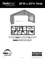
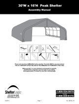
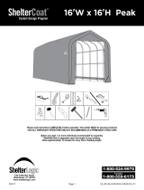
Before you start: 5 or more individuals recommended for assembly.
Assembly time is dependent upon the length of your building.
Allow approximately 15 minutes for every foot in building length.
Please read instructions COMPLETELY before assembly. This shelter MUST be securely anchored.
THIS IS A TEMPORARY STRUCTURE AND NOT RECOMMENDED AS A PERMANENT STRUCTURE.
18"
45 cm
+
/
-
28
'
W x 20
'
H Peak
ShelterCoat
TM
Custom Garage Program
1
/
2
"

05_GP-AA-XXXXXXA-028XXX20_H1Page 2
Risk of re. DO NOT smoke or use open ame devices (including grills, re pits, deep fryers, smokers or
lanterns) in or around the shelter. DO NOT store ammable liquids (gasoline, kerosene, propane, etc.) in
or around your shelter. Do not expose top or sides of the shelter to open re or other ame source.
WARNING:
PROPER ANCHORING OF THE FRAME IS THE RESPONSIBILITY OF THE CONSUMER.
ShelterLogic
®
Corp.
is not responsible for damage to the unit or the contents from acts of nature. Any shelter that is not anchored
securely has the potential to y away causing damage, and is not covered under the warranty. Periodically check the anchors to ensure
stability of shelter. ShelterLogic
®
Corp. cannot be responsible for any shelter that blows away. NOTE: Your shelter’s cover can be
quickly removed and stored prior to severe weather conditions. If strong winds or severe weather is forecast in your area, we
recommend removal of cover.
PROPER ANCHORING AND INSTALLATION OF FRAME:
Covered by U.S. Patents and patents pending: 6,871,614; 6,994,099; 7,296,584; D 430,306; D 415,571; D 414,564; D 409,310; D 415,572
A tight cover ensures longer life and performance. Always maintain a tight cover. Loose fabric can accelerate
deterioration of cover fabric. Immediately remove any accumulated snow or ice from the roof structure with a
broom, mop or other soft-sided instrument. Use extreme caution when removing snow from cover- always
remove from outside the structure. DO NOT use hard-edged tools or instruments like rakes or shovels to
remove snow. This could result in punctures to the cover. DO NOT use bleach or harsh abrasive products to
clean the fabric cover. Cover is easily cleaned with mild soap and water.
CARE AND CLEANING:
ATTENTION:
This shelter product is manufactured with quality materials. It is designed to t the ShelterLogic
®
Corp. custom fabric cover included.
ShelterLogic
®
Corp. Shelters offer storage and protection from damage caused by sun, light rain, tree sap, animal / bird excrement
and light snow. Please anchor this ShelterLogic
®
Corp. structure properly. See manual for more anchoring details. Proper anchoring,
keeping cover tight and free of snow and debris is the responsibility of the consumer. Please read and understand the installation detail,
warnings and cautions prior to beginning installation. If you have any questions call the customer service number listed below. Please
refer to the warranty card inside this package.
Prior to installation, consult with all local municipal codes regarding installation of temporary shelters.
Choose the location of your shelter carefully. DANGER: Keep away from electrical wires. Check for
overhead utility lines, tree branches or other structures. Check for underground pipes or wires before
you dig. DO NOT install near roof lines or other structures that could shed snow, ice or excessive run
off onto your shelter. DO NOT hang objects from the roof or support cables.
DANGER:
CAUTION:
Use CAUTION when erecting the frame. Use safety goggles during installation. Secure and bolt together
overhead poles during assembly. Beware of pole ends.
REPLACEMENT PARTS, ASSEMBLY, SPECIAL ORDERS:
Genuine ShelterLogic
®
Corp. replacement parts and accessories are available from the factory, including anchoring kits for nearly any
application, replacement covers, wall and enclosure kits, vent and light kits, frame parts, zippered doors and other accessories. All
items are shipped factory direct to your door.
This shelter carries a limited warranty against defects in workmanship. ShelterLogic
®
Corp. warrants to the Original Purchaser that if
properly used and installed, the product and all associated parts, are free from manufacturer’s defects for a period of:
1 YEAR FOR COVER FABRIC, END PANELS AND FRAMEWORK.
Warranty period is determined by date of shipment from ShelterLogic
®
Corp. for factory direct purchases or date of purchase from an authorized
reseller, (please save a copy of your purchase receipt). If this product or any associated parts are found to be defective or missing at the time of receipt,
ShelterLogic
®
Corp. will repair or replace, at it’s option, the defective parts at no charge to the original purchaser. Replacement parts or repaired parts
shall be covered for the remainder of the Original Limited Warranty Period. All shipping costs will be the responsibility of the customer. You must save
the original packaging materials for shipment back. If you purchased from a local dealer, all claims must have a copy of original receipt. After purchase,
please ll out and return warranty card for product registration. Please see warranty card for more details. This warranty gives you specic legal rights,
and you may also have other rights which vary from state to state.
WARRANTY:
QUESTIONS - CLAIMS - SPECIAL ORDERS? CALL OUR CUSTOMER SERVICE HOTLINE:
U.S. CUSTOMER SERVICE: 1-800-524-9970 INTERNATIONAL CUSTOMER SERVICE: 001-860-945-6442 CANADA CUSTOMER SERVICE: 1-800-559-6175
HOURS OF OPERATION: MON-FRI 8:00AM-8:00PM EST, SAT-SUN 8:00AM-4:30PM EST.
08192015

05_GP-AA-XXXXXXA-028XXX20_H1Page 3
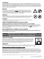
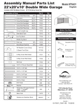
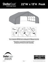
28'W x 20'H Peak Style Frame Assembly
Please read and understand instructions completely before assembly.
Lay out frame parts as shown.
ATTENTION:
FOR MISSING OR
REPLACEMENT PARTS
OR QUESTIONS,
PLEASE CONTACT
CUSTOMER SERVICE:
1.800.524.9970
CANADA 1.800.559.6175
Assembly
Reference #
Mfg.
Part #
Assembly
Reference #
Mfg.
Part #
1 800384 17 11106
2 800386 18 11107
3 800383 19 00828
4 800389 20 00825
5 800391 21 800435
6 800390 22 800385
7 11105 23 800438
8 11104 24 800436
9 11102 25 800440
10 800088 26 11005
11
WB601RS24
27
WB602RS1
12 800372 28 11134
13 11130 29 11133
14 11131 30 802051
15 800454 31 802050
16 00690 32 802011
Middle Ribs
Top Rail
End Rib
Wind Brace
Cross Rails
Cover
Rail
Cover
Rail
End Rib
Base Rail
1
23
6
5
24
3,28,16
8
23
9
22
2
23
3
24
9
22
10
14
16
9
8
1
2
9
7
7
7
31
5
19
21
9
1
25
14
26
25
31
23
2
22
22
17
13
16
17,13,16
18,13,16
1
4
1
4
4
8
9
21
26
9
19
9
7
12
15
16
9
9
9
31
30
8
11
11
13
16
10
14
16
14
14
16
12
15
16
12
15
16
11
29,16
18,13,16
18,13,16
18,13,16
19
11
12
28
16
10
14
16
12
15
16
12
28
16
30
8
9
31
25
26
21
32
32
32

05_GP-AA-XXXXXXA-028XXX20_H1Page 4
NOTE: FRAME EXTENSION KIT
Your model may have more middle ribs than shown in the illustration on pg.3. You will receive one extra rib for every
extra 4 ft. of building length that you purchase. The basic frame assembly will remain the same. The cover will be the
correct size for the length of the building.
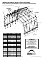
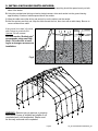
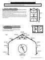
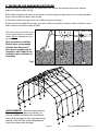
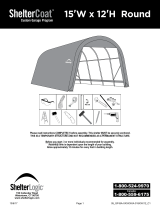
1. PLOTTING THE FRAME
Before building your shelter, you should choose a at area on
your property and plot your shelter.
A. Stake out the area for the shelter in the desired spot. The width of
the area should be at least equal to the width of the shelter and the
length should be equal to the length of the shelter Fig. 1.
B. Measure diagonally from corner to corner (A & B). These
measurements should be the same. If they are not equal the stakes
need to be adjusted until the width, length and inside measurements
are correct.
A
B
BUILDING
LENGTH
28 ft.
WIDTH
Fig.1
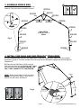
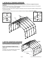
2. ASSEMBLE END RIBS
Assemble end ribs as shown in Fig. 2. Securely
fasten all of the joints with the hardware indicated.
Fig.2
Use #11131
5/16" x 2 3/4" L
Bolts
800384
800384
800385
800385
800386
800438 800438
800435
800386
800435
800383
800389800390
800391

05_GP-AA-XXXXXXA-028XXX20_H1Page 5
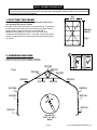
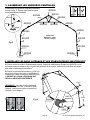
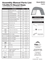
A. Place assembled rst end rib in the staked area. Place the ShelterLocks
®
(800372) on the uprights
as shown in Figure 4. From the outside of the rib insert the bolt through the upright and then through the
ShelterLock
®
.
B. Place the rst Side Rails (11104) over the
bolts and nest them into the ShelterLocks
®
. Install
the nut onto the bolt and HAND TIGHTEN THE
BOLT THAT CONNECTS TO THE END RIB.
NOTE: Sliding Cover Rails (11105) should be
attached to frame after Step 8, once cover is
placed over the frame. See Step 9.
3. ASSEMBLE MIDDLE RIBS
Assemble middle ribs as shown in Fig. 3. Securely
fasten all of the joints with the hardware indicated.
800384
800384
800385
800385
800386
800436
800386
800436
800383
800389800390
800391
800088 800088
800088
800436
00690
11131
Use #11131
5/16" x 2 3/4" L
Bolts
4. INSTALL SIDE RAILS AND SHELTERLOCK
®
STABILIZERS
Fig.3
Fig.4
800438
800438
11104
11104
800372
00690
800454

05_GP-AA-XXXXXXA-028XXX20_H1Page 6
B
B
C
C
D
D
Fig.5
11104
11104
11102
11102
800440
800372
800372
11134
11134
800440
800440
11131
11131
00690
00690
00690
00690
800440
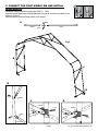
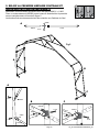
5. CONNECT THE FIRST MIDDLE RIB AND INSTALL
WIND BRACES
A
Assemble upper Wind Brace with parts 802011 + 11005.
Attach this and Wind Brace 800439 between the end rib and the rst middle rib as
shown in Figure 5.
Bolts should be inserted facing inside of the shelter.
802011 11005
11130
00690
802011
11005
802011
11005

05_GP-AA-XXXXXXA-028XXX20_H1Page 7
Fig.6
11102
11102
11102
11102
11102
11102
11102
11102
11102
11102
11102
11102
800440
A
A
B
B
C
C
11104
11102
800440
800372
800372
11134
800454
11131
11131
00690
00690
00690
00690
11102
11102
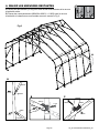
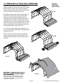
6. CONNECT THE REMAINING RIBS
A. Use Side Rails 11102 to connect remaining ribs and rear end rib.
B. Use Wind Braces 800439 and 802011 + 11005 between the end rib and the last
middle rib as shown in Fig. 6.
802011 + 11005

05_GP-AA-XXXXXXA-028XXX20_H1Page 8
28 ft.
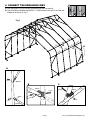
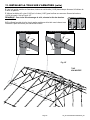
7. INSTALL TOP RAIL:
As with the Side Cross Rails, Use #11104 and #11102 Rails to make the Top Cross Rail:
A. Place the rst rail (#11104) under the end rib and secure it with bolt #11134 as shown in
Fig.7A. HAND-
TIGHTEN this bolt.
B. Connect the rails to each other, laying the #11102 cross rails over the middle ribs. Use bolt #11133.
Fig.7B
C. Place the last rail under the rear end rib. HAND-TIGHTEN this bolt.
Fig.7B
11134
00690
Fig.7A
11102
11104
00690
11133
11102
11102
8. SQUARING UP THE FRAME
A. Be sure the frame is in its nal location, which
needs to be as at and level as possible.
B. Measure across opposite corners.
These distances must be equal to within 1 inch.
C. Check that the front and rear of the frame
measures 28 feet in width.
28 ft.
Fig.8
800383

05_GP-AA-XXXXXXA-028XXX20_H1Page 9
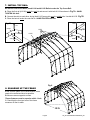
A. The anchors should be positioned at the four corners and the remaining should be spaced evenly on both
sides of the shelter.
B. Using the provided steel driving rod and a sledge hammer, drive each anchor into the ground leaving
approximately 8 inches of cable exposed above the surface.
C. Wrap the cable around the driving rod and pull up on the cable to set the anchor.
D. After the anchors are rmly set, wrap the cable around the foot, then close with a cable clamp. Be sure to
remove all slack from cable.
If the ground is too hard, dig a hole
with a shovel or post hole tool.
Optional: Fill with cement.
For best results, ShelterLogic
®
recommends using one Easy
Hook
™
Drive Anchor at each
leg for a stronger, more secure
installation.
9. INSTALL EASY-HOOK EARTH ANCHORS:
Fig.9
WARNING: Serious injury to persons or property
could result if cover is installed and shelter is not
completed and is left unattended. Shelter must
be securely anchored until completed.

05_GP-AA-XXXXXXA-028XXX20_H1Page 10
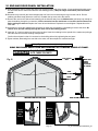
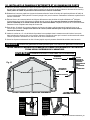
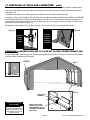
10. END AND DOOR PANEL INSTALLATION
SIDE
CROSS RAILS
WEBBING
ZIPPERS
TOP CROSS
RAIL
WRAP END
PANEL
EDGES
TO INSIDE
OF FRAME
INSIDE VIEW OF END RIB SIDE VIEW OF END RIB
WIND
BRACE
IMPORTANT!
DO NOT INSERT ANY PIPES
INTO THESE POCKETS.
WRAP END PANEL EDGES OVER AND AROUND PIPE TOWARDS INSIDE OF FRAME.
NOTE:
Keep Zippers closed when tightening end panels.
Thread
Webbing
Into
Ratchet
Webbing
and
Ratchets
Securing
End Panel
Fig.10
A. Hold end panel at the top center with white inner surface facing inside of the shelter. (If you purchased the white cover,
the inner face has the visible weld seams at the webbing pocket.) Wrap the edges of the fabric panel around the
end rib.
B. Disconnect top cross rail (the horizontal pipes that run from front to back along the top) from the end rib. Pull the
webbing (the black strap) below the cross rail. Reattach the top cross rail to the end rib.
C. Remove the nut from the side rail and carefully pull the side rail away from the ShelterLock
®
(pull away only enough to
pass the webbing through the connection). If this connection has the wind brace on it remove the wind brace end
before pulling the side rail. Replace the cross rail and wind brace. Replace the nut and tighten. Repeat this on the
other side.
D. At the bottom, where the webbing exits the pocket on each side of end panel, pull webbing to remove the slack. Be
careful not to pull the webbing through the other side of the webbing pocket.
E. Insert the “S”- Hook on ratchet into hole on the leg bend. Insert the webbing into the spindle of the ratchet and pull tight.
Wind the ratchet so that the webbing overlaps itself.
Position the end panel so that it is centered on the building before fully tightening the end panel.
F. Tighten ratchets, alternating from one side to the other, until the end panel is centered and tight.

05_GP-AA-XXXXXXA-028XXX20_H1Page 11
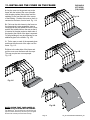
A. Lay the cover on the ground next to the
frame with the inside of the cover (the side
with the pipe pockets) facing down and the
webbing on the front and rear of the corner
of the building. Position the cover so that it is
centered to the frame, front to back. Fig. 11A
B. Fold over the side closest to the frame so
the pipe pocket is now accessible. Insert a
cover pipe at the rst middle rib from the front
and the rst middle rib from the rear so that it
is inserted in the pipe pocket on both ends of
the pipe but the center of the pipe is exposed.
For long buildings it may be necessary to use
additional pipes in the middle. Fig. 11B.
C. Tie the rope on each of the exposed pipes
and throw the other end of the rope over the
frame. Fig. 11C.
D. Move to the other side of the frame and
pull the cover over the frame with the rope.
This may require two or more people.
Fig. 11D.
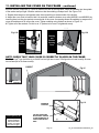
11. INSTALLING THE COVER ON THE FRAME
END PANELS
NOT SHOWN
FOR CLARITY.
NOTE: CHECK THAT YOUR COVER IS
CORRECTLY PLACED ON THE FRAME.
The ShelterLogic
®
logo should line up on the left front and
right rear corners near the top rail. If the logo is not legible,
the cover has not been put on the frame correctly.
Fig.11A
Fig.11B
Fig.11C
Fig.11D

05_GP-AA-XXXXXXA-028XXX20_H1Page 12
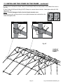
11. INSTALLING THE COVER ON THE FRAME - continued
E. After cover is centered on frame, insert a Cover Rail (#11105) into each pocket on the inside of the cover in
the roof.
F. Use 3-Way (#11106) and 4-Way (#11107) Clamps to connect them to the ribs. Hand-tighten bolts (#11130).
See Figure 11F.
NOTE: To avoid damage to fabric, face bolt heads towards cover.
G. Using cover rails, pull top portion of cover tightly downward and outward from the
center and tighten bolts.
11130
11106
00690
11130
11107
00690
Middle Rib Cross Rail ClampsEnd Rib Cross Rail Clamps
1110 5
1110 5
1110 5
1110 5
1110 5
COVER NOT
SHOWN FOR
CLARITY.
Fig.11F

05_GP-AA-XXXXXXA-028XXX20_H1Page 13
H. At the corners, insert the “S”- Hook on ratchet into hole on the leg bend. Insert the webbing into the spindle
of the ratchet and pull tight. Wind the ratchet so that the webbing overlaps itself. See Figure 11G.
I. Repeat these steps on the opposite side, then repeat this on the back side of the shelter.
J. Adjust the cover front to back so that it is centered. Install the bottom cover rails (#802051 and #802050) by
inserting them into the pipe pockets on each side of the cover. An opening allows the webbing to wrap around
cover rail and base rail to secure the cover. Tighten webbing using ratchet as shown in Figure 11J
K. Tighten all of the ratchets. Do this in an “X” pattern to be sure it is tightened evenly.
NOTE: CHECK THAT YOUR COVER IS CORRECTLY PLACED ON THE FRAME.
The ShelterLogic
®
logo should line up on the left front and right rear corners. If the logo does not read correctly, the cover
has not been put on the frame correctly.
Check and
tighten Ratchets
and Cross Rails
monthly to ensure
the cover is tight.
Cover Tightening Tip
TIGHTEN COVER DOWN
WITH RATCHET, STARTING
AT ONE END WORKING TO
OPPOSITE END ON BOTH
SIDES.
ASSEMBLED
COVER RAIL
11. INSTALLING THE COVER ON THE FRAME - continued
Thread
Webbing
Into
Ratchet
Fig.11G
Fig.11J
Fig.11I
Fig.11H
Webbing
and
Ratchets
Securing
Cover
CORRECT
INCORRECT

Page 14 05_GP-AA-XXXXXXA-028XXX20_H1
150 Callender Road
Watertown, CT 06795
www.shelterlogic.com
Veuillez lire TOUTES les instructions avant d'entreprendre l'assemblage. Cet abri DOIT être bien ancré.
CECI EST UNE STRUCTURE TEMPORAIRE, IL N'EST PAS RECOMMANDÉ D'EN FAIRE UNE STRUCTURE PERMANENTE.
Avant de commencer : Il faut 5 personnes ou plus pour le montage.
Le temps de montage dépend de la longueur de votre bâtiment.
Veuillez prévoir environ 15 minutes pour chaque pied de longueur du bâtiment.
1-800-524-9970
1-800-559-6175
Canada :
18 po
45 cm
+
/
-
28
'
/8,5m l. x 20
'
/6,1m h.
Pointu
ShelterCoat
TM
Programme de Garage Personnalisé

Page 15 05_GP-AA-XXXXXXA-028XXX20_H1
Risque d’incendie. Ne fumez PAS et n’utilisez AUCUN dispositif produisant des ammes (p. ex., un
barbecue, un foyer, une friteuse, un fumoir ou une lanterne) à proximité de l’abri. Ne rangez PAS des
liquides inammables (essence, kérosène, propane, etc.) à proximité de l’abri. N’exposez pas le dessus
ou les parois de l’abri au feu ou à toute source d’incendie.
AVERTISSEMENT :
IL INCOMBE À L’UTILISATEUR D’ASSURER L’ANCRAGE ADÉQUAT DE L’ARMATURE.
ShelterLogic
®
Corp.
n’assume aucune responsabilité pour les dommages causés à l’abri ou à son contenu par les catastrophes
naturelles. Tout abri n’étant pas ancré solidement risque de s’envoler et de causer des dommages, ce qui n’est pas couvert par la
garantie. Vériez périodiquement les ancrages pour assurer la stabilité de l’abri. ShelterLogic
®
Corp. ne peut être tenue responsable
d’un abri qui s’envole. REMARQUE : La toile de l’abri peut être retirée rapidement pour être entreposée en prévision de mauvais
temps. Si des vents forts ou du mauvais temps sont prévus pour votre région, nous vous recommandons d’enlever la toile de l’abri.
ANCRAGE ET INSTALLATION DE L’ARMATURE :
Brevets Américains et brevets en instance : 6,871,614; 6,994,099; 7,296,584; D 430,306; D 415,571; D 414,564; D 409,310; D 415,572
Une toile bien tendue assure une longue durée utile. Gardez toujours la toile bien tendue. Une toile desserrée
accélère la détérioration du tissu. Enlevez sans attendre toute accumulation de débris sur le toit à l’aide d’un
balai, d’une vadrouille ou d’un autre outil souple. Soyez très prudent au moment d’enlever la neige de la toile.
Enlevez-la toujours à partir de l’extérieur de la structure. N’utilisez PAS d’outils rigides comme des râteaux
ou des pelles pour enlever la neige, car ils risqueraient de perforer la toile. N’utilisez PAS de javellisants ou
d’abrasifs pour nettoyer la toile. Utilisez tout simplement de l’eau savonneuse pour nettoyer la toile.
ENTRETIEN ET NETTOYAGE :
ATTENTION :
Cet abri est fabriqué avec des matériaux de qualité. Il est conçu en fonction de la toile adaptée ShelterLogic
®
Corp. fournie. Les abris
ShelterLogic
®
Corp. offrent de l’espace de rangement et de la protection contre les dommages causés par le soleil, la pluie légère,
la sève, les excréments d’animaux ou d’oiseaux et la neige légère. Veuillez ancrer adéquatement cette structure ShelterLogic
®
Corp.
Consultez le guide pour connaître les détails sur l’ancrage. Il incombe à l’utilisateur d’assurer un ancrage adéquat et de garder la
toile bien tendue et exempte de neige ou de débris. Veuillez lire et vous assurer de bien comprendre les détails de l’installation, les
avertissements et les mises en garde avant d’entreprendre l’installation. Pour toute question, téléphonez au service à la clientèle au
numéro ci-dessous. Veuillez aussi consulter la che de garantie se trouvant dans l’emballage.
Avant d’entreprendre l’installation, vériez tous les règlements municipaux concernant les abris
temporaires. Choisissez soigneusement l’emplacement de l’abri. DANGER : Tenez-vous éloigné
des ls électriques. Évitez les lignes électriques, les branches d’arbres et les autres types de
structures. Avant de creuser, vériez la présence de tuyaux ou de ls enfouis. N’installez PAS cet abri
à proximité d’un toit ou de toute autre structure pouvant laisser tomber de la neige, de la glace ou des
débris. Ne suspendez AUCUN objet au toit ou aux câbles de soutien.
DANGER :
ATTENTION :
Soyez PRUDENT au moment de monter l’armature. Portez des lunettes de sécurité durant l’installation. Boulonnez les mâts
supérieurs durant l’assemblage. Prenez garde aux extrémités des mâts.
PIÈCES DE RECHANGE ET COMMANDES SPÉCIALES :
Des pièces de rechange et des accessoires d’origine ShelterLogic
®
Corp. sont disponibles à l’usine, notamment des nécessaires
d’ancrage pour presque toute utilisation, des toiles de rechange, des ensembles de parois, des nécessaires d’aération ou d’éclairage,
des pièces d’armature, des portes à glissière, etc. Tous ces articles sont expédiés directement chez vous à partir de l’usine.
Cet abri offre une garantie limitée contre les défauts de fabrication. ShelterLogic
®
Corp. garantit à l’acheteur initial que s’il est installé et utilisé
adéquatement, cet article et toutes ses pièces sont exempts de défaut de fabrication pendant une période de :
1 AN POUR LA TOILE, LES PANNEAUX D’EXTRÉMITÉ ET L’ARMATURE.
La période de garantie est calculée à partir de la date d’expédition par ShelterLogic
®
Corp. pour les achats faits directement à l’usine ou de la date
d’achat chez un revendeur autorisé (veuillez conserver votre reçu d’achat). Si cet article ou une de ses pièces est jugé défectueux ou qu’il est manquant
au moment de la réception, ShelterLogic
®
Corp. réparera ou remplacera, à sa discrétion, toute pièce défectueuse sans frais pour l’acheteur initial.
Toute pièce remplacée ou réparée demeure couverte durant le reste de la période de garantie limitée initiale. Tous les frais d’expédition sont à la charge
du client. Les pièces et les composants de rechange sont expédiés contre remboursement. Veuillez conserver le matériel d’emballage initial pour l’envoi
de retour. Pour les achats faits chez un marchand local, toute réclamation doit être accompagnée d’une copie du reçu initial. Après l’achat, veuillez
remplir et expédier la che de garantie pour inscrire l’article. Veuillez consulter la che de garantie pour obtenir de plus amples renseignements. Cette
garantie vous donne des droits juridiques spéciques, et vous pouvez également avoir d'autres droits qui varient d'un état à état.
GARANTIE :
QUESTIONS, RÉCLAMATIONS OU COMMANDES SPÉCIALES – LIGNE D’AIDE DU SERVICE À LA CLIENTÈLE :
ÉTATS-UNIS : 1-800-524-9970 SERVICE À LA CLIENTÈLE INTERNATIONAL : 001-860-945-6442 CANADA : 1-800-559-6175
HEURES D’OUVERTURE : DU LUNDI AU VENDREDI DE 8 H 30 À 20 H (HE), SAMEDI ET DIMANCHE DE 8 H 30 À 17 H (HE)
07212015

Page 16 05_GP-AA-XXXXXXA-028XXX20_H1
Rail de
toile
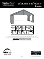
Veuillez lire et vous assurer de bien comprendre TOUTES les instructions avant
d'entreprendre l'assemblage.
Étalez les pièces de l'armature,
comme le montre l'illustration.
ATTENTION :
EN CAS DE PIÈCE MANQUANTE
ET POUR TOUTE PIÈCE DE
RECHANGE OU TOUTE QUESTION,
VEUILLEZ COMMUNIQUER AVEC
LE SERVICE À LA CLIENTÈLE :
1.800.524.9970
CANADA 1.800.559.6175
Abri à toit pointu, 8,5 m (larg.) x 6,1 m (haut.) - Assemblage de l'armature
Tube supérieur
Rails
latéraux
Rail de
toile
Nervures
centrales
Nervure
d'extrémité
Nervure
d'extrémité
Rail de base
1
23
6
5
24
3,28,16
8
23
9
22
2
23
3
24
9
22
10
14
16
9
8
1
2
9
7
7
7
31
5
19
21
9
1
25
14
26
25
31
23
2
22
22
17
13
16
17,13,16
18,13,16
1
4
1
4
4
8
9
21
26
9
19
9
7
12
15
16
9
9
9
31
30
8
11
11
13
16
10
14
16
14
14
16
12
15
16
12
15
16
11
29,16
18,13,16
18,13,16
18,13,16
19
11
12
28
16
10
14
16
12
15
16
12
28
16
30
8
9
31
25
26
21
Contreventement
N°
d'assemblage
N° de
pièce
N°
d'assemblage
N° de
pièce
1 800384 17 11106
2 800386 18 11107
3 800383 19 00828
4 800389 20 00825
5 800391 21 800435
6 800390 22 800385
7 11105 23 800438
8 11104 24 800436
9 11102 25 800440
10 800088 26 11005
11
WB601RS24
27
WB602RS1
12 800372 28 11134
13 11130 29 11133
14 11131 30 802051
15 800454 31 802050
16 00690 32 802011
32
32
32

Page 17 05_GP-AA-XXXXXXA-028XXX20_H1
Fig.2
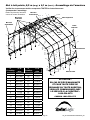
REMARQUE : NÉCESSAIRE DE RALLONGE D'ARMATURE
Votre abri peut comporter davantage de nervures centrales que l'illustration de la page 16. Vous recevez une
nervure additionnelle pour chaque section supplémentaire de 1,2 m. L'assemblage de l'armature de base reste le
même. La taille de la toile correspondra à la longueur de l'abri.
2. ASSEMBLEZ LES NERVURES
D’EXTRÉMITÉ
Assemblez les nervures d'extrémité comme
le montre la g. 2. Serrez bien tous les joints
avec les xations illustrées.
A
B
Longueur
de l'abri
8,5 m
LARGEUR
Fig.1
1. TRACEZ L'EMPLACEMENT.
Avant d’assembler l’abri, vous devez choisir une surface
plane et y tracer son emplacement.
A. Piquetez l’emplacement de l’abri à l’endroit choisi. La largeur de
l’emplacement doit être au moins égale à la largeur de l’abri et sa
longueur, à celle de l’abri (g. 1).
B. Mesurez la distance en diagonale entre les coins (A et B). Cette
distance doit être égale dans tous les cas. Sinon, les piquets doivent
être déplacés jusqu’à ce que la largeur, la longueur et les mesures
soient correctes.
Utilisez les
boulons n° 11131
(5/16 x 2 3/4 po)
800384
800384
800385
800385
800386
800438 800438
800435
800386
800435
800383
800389800390
800391

Page 18 05_GP-AA-XXXXXXA-028XXX20_H1
Fig.4
3. ASSEMBLEZ LES NERVURES CENTRALES
Assemblez les nervures centrales comme le
montre la g. 3. Serrez bien tous les joints
avec les xations illustrées.
Utilisez les
boulons n° 11131
(5/16 x 2 3/4 po)
A. Placez la nervure avant à l'emplacement piqueté. Placez les stabilisateurs ShelterLock (800372) sur les
montants comme le montre la g. 4. À partir de l'extérieur de la nervure, insérez le boulon dans le montant,
puis dans le stabilisateur ShelterLock
®
.
B. Placez les premiers rails latéraux (11104) sur
les boulons et logez-les dans les stabilisateurs
ShelterLock. Posez un écrou sur chaque boulon
et SERREZ À LA MAIN LE BOULON QUI
RELIE LA NERVURE D'EXTRÉMITÉ.
REMARQUE : Les rails de toile coulissants
(11105) doivent être xés à l'armature après
l'étape 8, une fois que la toile est placée sur
l'armature. Voir l'étape 9.
4. INSTALLEZ LES RAILS LATÉRAUX ET LES STABILISATEURS SHELTERLOCK
®
Fig.3
11104
11104
800372
00690
800454
800384
800384
800385
800385
800386
800436
800386
800436
800383
800389800390
800391
800088 800088
800088
800436
00690
11131
800438
800438

Page 19 05_GP-AA-XXXXXXA-028XXX20_H1
A
B
C
Fig.5
800442
800442
A
B C
11104
11104
11102
11102
800440
800372
800372
11134
11134
800440
800440
11131
11131
00690
00690
00690
00690
800440
5. RELIEZ LA PREMIÈRE NERVURE CENTRALE ET
INSTALLEZ LES CONTREVENTEMENTS
Assemblez contreventement supérieure avec des pièces 802011 + 11005.
Fixez un contreventement (800439) entre la nervure d'extrémité et la première
nervure centrale comme le montre la gure 5.
Les boulons xés aux traverses doivent être orientés vers l'intérieur de l'abri.
A
802011 11005
11130
00690

Page 20 05_GP-AA-XXXXXXA-028XXX20_H1
Fig.6
11102
11102
11102
11102
11102
11102
11102
11102
11102
11102
11102
11102
800440
A
A
B
B
C
C
11104
11102
800442
800440
800372
800372
11134
800454
11131
11131
00690
00690
00690
00690
11102
11102
802011 + 11005
6. RELIEZ LES NERVURES RESTANTES
A. Utilisez les rails latéraux (11102) pour relier les nervures restantes et la nervure
d'extrémité arrière.
B. Placez des contreventements (800439 et 802011 + 11005) entre la nervure
d'extrémité et la dernière nervure centrale comme le montre la Fig. 6.
La page est en cours de chargement...
La page est en cours de chargement...
La page est en cours de chargement...
La page est en cours de chargement...
La page est en cours de chargement...
La page est en cours de chargement...
-
 1
1
-
 2
2
-
 3
3
-
 4
4
-
 5
5
-
 6
6
-
 7
7
-
 8
8
-
 9
9
-
 10
10
-
 11
11
-
 12
12
-
 13
13
-
 14
14
-
 15
15
-
 16
16
-
 17
17
-
 18
18
-
 19
19
-
 20
20
-
 21
21
-
 22
22
-
 23
23
-
 24
24
-
 25
25
-
 26
26


ShelterLogic 86071.0 Le manuel du propriétaire
- Taper
- Le manuel du propriétaire
dans d''autres langues
- English: ShelterLogic 86071.0 Owner's manual
Documents connexes
-
ShelterLogic 86062.0 Le manuel du propriétaire
-
 ShelterLogic 81848 Le manuel du propriétaire
-
 ShelterLogic ShelterLogic ShelterCoat Wind and Snow Rated Waterproof Round Portable Garage Shelter Le manuel du propriétaire
-
-
-
 ShelterLogic 78431 Mode d'emploi
-
 ShelterLogic 79431.0 Guide d'installation
-
 ShelterLogic 82143 Manuel utilisateur
-
 ShelterLogic 95334.0 Le manuel du propriétaire
-
 ShelterLogic 95333.0 Mode d'emploi


