IMG STAGELINE MPX-30DMP Manuel utilisateur
- Catégorie
- Amplificateur d'instruments de musique
- Taper
- Manuel utilisateur

ELECTRONICS FOR SPECIALISTS ELECTRONICS FOR SPECIALISTS ELECTRONICS FOR SPECIALISTS ELECTRONICS FOR SPECIALISTS
BEDIENUNGSANLEITUNG
INSTRUCTION MANUAL
MODE D’EMPLOI
ISTRUZIONI PER L’USO
GEBRUIKSAANWIJZING
MANUAL DE INSTRUCCIONES
INSTRUKCJA OBSŁUGI
SIKKERHEDSOPLYSNINGER
SÄKERHETSFÖRESKRIFTER
TURVALLISUUDESTA
Stereo-DJ-Mischpult
mit MP3-Spieler
Stereo DJ Mixer
with MP3 Player
MPX-30DMP
Bestell-Nr. • Order No. 20.2760

2
Deutsch ...........Seite 4
English ............Page 7
Français ...........Page 10
Italiano............Pagina 13
Nederlands ........Pagina 16
Español ...........Página 19
Polski .............Strona 22
Dansk .............Sida 25
Svenska ...........Sidan 25
Suomi.............Sivulta 25
ELECTRONICS FOR SPECIALISTS ELECTRONICS FOR SPECIALISTS ELECTRONICS FOR SPECIALISTS ELECTRONICS FOR SPECIALISTS

3
12
3
11
12
13
14
15
16
17
18
19
10
9
8
7
6
5
4
3
2
1
A
B
C
D
MID
+12
CUT
-
32 dB
+12
CUT
-
32 dB
GAIN
MAXMIN
LOW
+12
CUT
-
32 dB
HIGH
MID
+12
CUT
-
32 dB
+12
CUT
-
32 dB
GAIN
MAXMIN
LOW
+12
CUT
-
32 dB
HIGH
MID
+12
CUT
-
32 dB
+12
CUT
-
32 dB
GAIN
MAXMIN
MAXMIN
MAXMIN
MAXMIN
LOW
+12
CUT
-
32 dB
HIGH
MIC
LINE 1
PHONO 1 PHONO 2 MP3 PHONO 3 LINE 3
C.F. CONTROLS
REVERSE
CURVE
ON OFF
TALK
0
1
2
3
4
5
6
7
8
9
10
0
1
2
3
4
5
6
7
8
9
10
0
1
2
3
4
5
6
7
8
9
10
0
1
2
3
4
5
6
7
8
9
10
0
1
2
3
4
5
6
7
8
9
10
0
1
2
3
4
5
6
7
8
9
10
LINE 2
PFL MASTER
CROSSFADER
PFL SELECT
CH1
CH2
CH3
MASTER
BAL
RL
BOOTH
PFL
MIC
ON
11
8
5
0 dB
-5
-9
-12
-15
-20
-25
L R
CH 1
CH 2
CH 3
C
MPX-30DMP
MPX-30DMP
21
3
21
3
23 24 25 26 27
20
21
22
28
POWER
GND GND
LINE 1
PHONO 1
INPUT 1INPUT 2
LINE 2 PHONO 2
INPUT 3
LINE 3 PHONO 3RECBOOTHMASTER
OUTPUT
R
BAL.
L
BAL.
LINE 1 /
PHONO 1
R
L
230V~
50Hz
FUSE
MPX-30DMP
➀
➁

4
Deutsch
English
English Page
Français
Français Page
Italiano
Italiano Pagina
Español
Español Página
Polski
Polski Strona
Nederlands
Nederlands Pagina
Dansk
Dansk Sida
Suomi
Suomi Sivulta
Deutsch
Deutsch Seite
Stereo-DJ-Mischpult
Diese Anleitung richtet sich an Benutzer
mit Grundkenntnissen in der Audiotechnik.
Bitte lesen Sie die Anleitung vor dem Betrieb
gründlich durch und heben Sie sie für ein spä-
teres Nachlesen auf.
Auf der ausklappbaren Seite 3 finden
Sie alle beschriebenen Bedienelemente und
Anschlüsse.
1 Übersicht der Anschlüsse
und Bedienelemente
1.1 Ober- und Vorderseite
1 MP3-Spieler
A
USB-Buchse zum Einstecken eines
USB-Sticks oder zum Anschluss einer
Festplatte mit eigener Stromversorgung
B Steckplatz für eine SD / SDHC-Karte
C Display, zeigt
in der oberen Zeile
– das angewählte Abspielmedium („U“
für USB-Speicher, „S“ für SD / SDHC-
Karte) und die Nummer des Titels
bzw. im Modus „Stop“ die Anzahl
der Titel
– den Dateinamen des Titels
in der unteren Zeile
– den Betriebsmodus („Play“, „Pause“
„Stop“)
– abwechselnd die bereits gespielte Zeit
des Titels und seine Gesamtlaufzeit
bzw. im Modus „Stop“ die Zeitan-
zeige „000:00“
– „All“ bei ständiger Wiederholung
aller Titel oder „One“ bei ständiger
Wiederholung eines Titels
D Bedientasten
– Taste
II , um das Abspielen zu starten
und zu unterbrechen
– Taste , um das Abspielen zu beenden
– Taste , zum Umschalten zwischen
ständiger Wiederholung eines Titels
(Anzeige „One“) oder aller Titel (An-
zeige „All“)
– Tasten
I
und
I
, um einen Titel
vor oder zurück zu springen; für den
schnellen Vor- oder Rücklauf im Titel
die jeweilige Taste gedrückt halten
2
Mikrofoneingang (kombinierte Buchse
XLR / 6,3-mm-Klinke, sym.) für Kanal CH 1
3
Regler GAIN für die Eingangsverstärkung,
für jeden Eingangskanal
4 Klangregler, für jeden Eingangskanal
HIGH : Höhen, MID : Mitten, LOW : Tiefen
5
Eingangswahlschalter,
für jeden Eingangskanal
CH 1 links Eingang MIC
rechts Eingang LINE 1/ PHONO 1
CH 2 links Eingang PHONO 2
Mitte Eingang LINE 2
rechts MP3-Spieler
CH 3 links Eingang PHONO 3
rechts Eingang LINE 3
6 Fader zum Einstellen des Kanalpegels,
für jeden Eingangskanal
7
Taste TALK (mit Kontroll-LED) zum
Stummschalten der Kanäle CH 2 und CH 3
bei Mikrofondurchsagen
8
Schalter REVERSE zum Auswählen auf
welche Seite des Crossfaders (10) die
Kanäle CH 2 und CH 3 geschaltet werden
ON links Kanal CH 3, rechts Kanal CH 2
OFF links Kanal CH 2, rechts Kanal CH 3
9
Schalter CURVE für das Überblendverhal-
ten des Crossfaders (10)
weiches, gleichmäßiges Überblen-
den
hartes Überblenden mit einem wei-
ten Bereich, in dem beide Kanäle
gleich laut zu hören sind
10 Überblendregler (Crossfader) für die Ka-
näle CH 2 und CH 3
Wird die Überblendfunktion nicht benö-
tigt, den Crossfader in die Mitte schieben.
11 Betriebsanzeige
12
Stereo-Pegelanzeige für das mit dem
Regler MASTER (13) eingestellte Sum-
mensignal
13
Gesamt-Pegelregler MASTER: bestimmt
den Pegel des Summensignals, das über
die Ausgänge R BAL. / L BAL. und MASTER
(23) ausgegeben wird
14
Balance-Regler für das mit dem Regler
MASTER (13) eingestellte Summensignal
15
Gesamt-Pegelregler BOOTH: bestimmt
den Pegel des Summensignals, das über
den BOOTH-Ausgang (24) ausgegeben
wird
16
Lautstärkeregler für den Kopfhöreraus-
gang (19)
17
Vorhörtaste für jeden Eingangskanal
(mit Kontroll-LED): bei gedrückter Taste
lässt sich das zugehörige Kanalsignal vor
dem Fader (6) über einen Kopfhörer an
der Buchse (19) abhören (PFL = „Pre
Fader Listening“).
18 Regler zur Auswahl des Abhörsignals für
den Kopfhörerausgang (19)
Position PFL
Vorhören der Kanäle, deren Taste PFL
SELECT (17) gedrückt ist
Position MASTER
Abhören der Signalsumme vor den
Ausgangsreglern (13, 15)
19
6,3-mm-Klinkenbuchse zum Anschluss
eines Stereo-Kopfhörers (Impedanz
min.8 Ω)
1.2 Rückseite
20 Ein- /Ausschalter POWER
21
Netzbuchse zum Anschluss an eine Steck-
dose (230 V/ 50 Hz) über das beiliegende
Netzkabel
22
Halterung für die Netzsicherung; eine
geschmolzene Sicherung nur durch eine
gleichen Typs ersetzen
23
Stereo-Ausgänge R BAL. / L BAL. (XLR-Ein
-
baustecker, sym.) und MASTER (Cinch -
Buchsen) zum Anschluss des Verstärkers
für die Beschallung
Der XLR-Ausgang und der Cinch-Ausgang
können auch gleichzeitig zum Anschluss
von zwei Verstärkern verwendet werden.
Der Ausgangspegel wird mit dem Regler
MASTER (13) eingestellt.
24
Stereo-Ausgang BOOTH (Cinch-Buchsen)
für den Anschluss eines weiteren Verstär-
kers, z. B. für eine Monitoranlage oder
eine Nebenraum-Beschallung; der Aus-
gangspegel wird mit dem Regler BOOTH
(15) eingestellt
25
Stereo-Ausgang REC (Cinch-Buchsen) für
den Anschluss eines Aufnahmegerätes;
der Aufnahmepegel ist unabhängig von
der Stellung der Ausgangsregler (13, 15)
26
Stereo-Eingänge (Cinch-Buchsen) zum
Anschluss von Tonquellen an die Kanäle
CH 1 bis CH 3
INPUT 2, INPUT 3:
Eingänge PHONO für Plattenspieler mit
Magnetsystem,
Eingänge LINE für Geräte mit Line-Pe-
gel-Ausgang, z. B. CD-Spieler, Tapedeck,
Radio
INPUT 1:
Der Eingang kann mit der daneben liegen-
den Taste zwischen PHONO und LINE um-
geschaltet werden:
☞
siehe Position 27.
27 LINE / PHONO-Umschalter, um den dane-
ben liegenden Eingang für Kanal CH 1
auf Line-Signalpegel (Taste ausgerastet)
oder Phono-Signalpegel (Taste gedrückt)
zu schalten
28 Masse-Klemmschrauben GND für ange-
schlossene Plattenspieler

5
Deutsch
2 Hinweise für den
sicherenGebrauch
Das Gerät entspricht allen relevanten Richt-
linien der EU und trägt deshalb das -Zei-
chen.
WARNUNG
Das Gerät wird mit lebens-
gefährlicher Netzspannung
versorgt. Nehmen Sie deshalb
niemals selbst Eingriffe daran
vor. Durch unsachbemäßes
Vorgehen besteht die Gefahr
eines elektrischen Schlages.
•
Das Gerät ist nur zur Verwendung im In-
nenbereich geeignet. Schützen Sie es vor
Tropf- und Spritzwasser, hoher Luftfeuch-
tigkeit und Hitze (zulässiger Einsatztempe-
raturbereich 0 – 40 °C).
•
Stellen Sie keine mit Flüssigkeit gefüllten
Gefäße, z. B. Trinkgläser, auf das Gerät.
•
Ziehen Sie sofort den Netzstecker aus der
Steckdose:
1. wenn sichtbare Schäden am Gerät oder
am Netzkabel vorhanden sind,
2.
wenn nach einem Sturz oder Ähnlichem
der Verdacht auf einen Defekt besteht,
3. wenn Funktionsstörungen auftreten.
Lassen Sie das Gerät in jedem Fall in einer
Fachwerkstatt reparieren.
•
Ziehen Sie den Netzstecker nie am Kabel
aus der Steckdose, fassen Sie immer am
Stecker an.
•
Verwenden Sie zum Reinigen nur ein tro-
ckenes, weiches Tuch, niemals Wasser oder
Chemikalien.
•
Wird das Gerät zweckentfremdet, nicht
richtig angeschlossen, falsch bedient oder
nicht fachgerecht repariert, kann keine
Haftung für daraus resultierende Sach-
oder Personenschäden und keine Garantie
für das Gerät übernommen werden.
Soll das Gerät endgültig aus dem
Betrieb genommen werden, überge
-
ben Sie es zur umweltgerechten Ent
-
sorgung einem örtlichen Recycling-
betrieb.
3 Einsatzmöglichkeiten
Das 3-Kanal-Mischpult MPX-30DMP ist für
beliebige DJ-Anwendungen im privaten oder
professionellen Bereich geeignet. Das Gerät
bietet Anschlussmöglichkeiten für Geräte mit
Line-Pegel (z. B. CD-Spieler), Plattenspieler
und ein DJ-Mikrofon. Als zusätzliche Ton-
quelle steht der integrierte MP3-Spieler zur
Verfügung, mit dem sich MP3-Audiodateien
von USB-Speichern (z. B. USB-Sticks) und
SD / SDHC-Karten (max. 32 GB) abspielen
lassen. Alle Tonquellen können über einen
Kopfhörer vorgehört werden („Pre Fader Lis-
tening“).
Das Mischpult kann sowohl frei aufgestellt
als auch in ein Bedienpult eingebaut werden.
4 Anschluss
Vor dem Anschluss bzw. vor dem Verändern
von Anschlüssen das Mischpult und die an-
zuschließenden Geräte ausschalten.
1)
Die Stereo-Tonquellen an die entspre-
chenden Cinch-Eingangsbuchsen (26) der
Kanäle CH 1 bis CH 3 anschließen (weiße
Buchse L = linker Kanal; rote Buchse R
=rechter Kanal):
Geräte mit Line-Pegel-Ausgang (z. B.
CD-Spieler, Tapedeck, Radio) lassen sich
anschließen an
– den Eingang LINE 1/ PHONO 1 von Kanal
CH 1; die daneben liegende Taste (27)
muss dazu ausgerastet sein
– den Eingang LINE 2 von Kanal CH 2
– den Eingang LINE 3 von Kanal CH 3
Plattenspieler mit Magnetsystem lassen
sich anschließen an
– den Eingang LINE 1/ PHONO 1 von Kanal
CH 1; die daneben liegende Taste (27)
muss dazu gedrückt sein
– den Eingang PHONO 2 von Kanal CH 2
– den Eingang PHONO 3 von Kanal CH 3
Ist am Anschlusskabel des Plattenspielers
ein separates Massekabel vorhanden, die-
ses mit einer Klemmschraube GND (28)
verbinden.
2) Ein Mikrofon lässt sich über einen XLR-
Stecker oder einen 6,3-mm-Klinkenstecker
an die symmetrisch beschaltete Buchse
MIC(2) anschließen.
3)
Zum Anschluss von Verstärkern stehen
mehrere Stereoausgänge zur Verfügung:
– symmetrisch beschalteter XLR-Ausgang
R BAL. / L BAL. und asymmetrisch beschal
-
teter Cinch-Ausgang MASTER (23): An
einen dieser Ausgänge sollte der Haupt-
verstärker für die Beschallung angeschlos-
sen werden. Der XLR-Ausgang sollte
bevorzugt verwendet werden, da die
symmetrische Signalübertragung einen
besseren Schutz gegen Störeinstrahlun-
gen bietet, die besonders bei längeren
Anschlusskabeln auftreten können.
Der XLR-Ausgang und der Cinch-Aus-
gang können auch gleichzeitig zum An-
schluss von zwei Verstärkern verwendet
werden.
– Ausgang BOOTH (24): Hier kann z. B. ein
Verstärker für eine Monitoranlage oder
für eine Nebenraum-Beschallung ange-
schlossen werden.
4)
Sollen Tonaufnahmen gemacht werden,
das Aufnahmegerät an den Stereo-
Ausgang REC (25) anschließen. Der Auf-
nahmepegel ist unabhängig von der Stel-
lung der Ausgangsregler MASTER (13) und
BOOTH (15).
5)
Zum Vorhören der Eingangskanäle oder
zum Abhören des Summensignals vor den
Ausgangsreglern MASTER und BOOTH
kann ein Kopfhörer (Impedanz min. 8 Ω)
über einen 6,3-mm-Klinkenstecker an den
Stereo-Ausgang (19) angeschlossen
werden
.
6)
Das beiliegende Netzkabel an die Netz-
buchse (21) anschließen und den Stecker
in eine Netzsteckdose (230 V/ 50 Hz)
stecken.
5 Bedienung
Vor dem Einschalten die Ausgangsregler
MASTER (13) und BOOTH (15) auf Minimum
stellen, um Einschaltgeräusche zu vermeiden.
Das Mischpult wird mit dem Netzschalter
POWER (20) ein- und ausgeschaltet. Bei ein-
geschaltetem Gerät leuchtet die Betriebsan-
zeige ON (11).
VORSICHT
Stellen Sie die Lautstärke der
Audioanlage und die Kopfhörer-
lautstärke nie sehr hoch ein.
Hohe Lautstärken können auf
Dauer das Gehör schädigen!
Das Ohr gewöhnt sich an hohe
Lautstärken und empfindet sie
nach einiger Zeit als nicht mehr
so hoch. Darum erhöhen Sie
eine hohe Lautstärke nach der
Gewöhnung nicht weiter.
5.1 Mischen der Tonquellen
Überblenden zwischen zwei Kanälen
1)
Mit den Kippschaltern (5) für jeden Ein-
gangskanal die gewünschte Tonquelle
anwählen:
CH 1 linke Position für das Mikrofon am
Eingang MIC
rechte Position für das Gerät am
Eingang LINE 1/ PHONO 1
CH 2 linke Position für das Gerät am Ein-
gang PHONO 2
mittlere Position für das Gerät
am Eingang LINE 2
rechte Position für den integrierten
MP3-Spieler
CH 3 linke Position für das Gerät am Ein-
gang PHONO 3
rechte Position für das Gerät am
Eingang LINE 3
2)
Zur Pegelangleichung und Klangkorrektur
der Eingangssignale, folgende Grundein-
stellungen durchführen:
a)
Alle Kanalfader (6) auf Minimum stellen.
Alle Gain-Regler (3), Klangregler (4) und
den Crossfader (10) in die Mittelposition
stellen.
b)
Leuchtet die LED über der Taste TALK
(7), die Taste zum Ausschalten der Talk-
over-Funktion ausrasten.
c) Den Ausgangsregler MASTER (13) auf
ca.
2
⁄
3
des Maximums aufdrehen.
d) Ein Tonsignal (z.B. Musikstück) auf den
ersten benutzten Eingangskanal geben
und den zugehörigen Fader (6) bis ca.
2
⁄
3
des Maximums aufziehen.
e)
Mit dem Regler GAIN (3) des Kanals den
Pegel so aussteuern, dass die Pegelan-
zeige (12) bei den lautesten Passagen im
0-dB-Bereich aufleuchtet. Den Klang mit
den Reglern HIGH, MID und LOW (4) ein-
stellen. Danach die Aussteuerung ggf.
mit dem Regler GAIN korrigieren. Nach
der Gain- und Klangeinstellung den
Kanalfader wieder auf Minimum stellen.
f)
Die Schritte d) und e) für die übrigen ver-
wendeten Eingangskanäle wiederholen.
Hinweis: Diese Bedienschritte dienen nur als
Hilfes tellung, es sind auch andere Vorgehensweisen
zur Grundeinstellung der Eingangskanäle möglich.

6
Deutsch
3)
Nach der Grundeinstellung können die
Eingangssignale mit den Kanalfadern (6)
im gewünschten Lautstärkeverhältnis ge-
mischt oder ein- und ausgeblendet werden.
4)
Für das Summensignal an den Ausgängen
R BAL. / L BAL. und MASTER (23) mit dem
Ausgangsregler MASTER (13) die endgül-
tige Lautstärke einstellen und mit dem
Regler BAL (14) die Stereo-Balance. Der
Signalpegel lässt sich an der Pegelanzeige
(12) ablesen. In der Regel wird bei 0 dB
eine optimale Aussteuerung erreicht. Ist
der Ausgangspegel des Mischpults jedoch
für den angeschlossenen Verstärker zu
hoch oder zu niedrig, muss das Summen-
signal entsprechend höher oder niedriger
eingestellt werden.
Für einen an den Buchsen BOOTH (24)
angeschlossenen Verstärker die Lautstärke
mit dem Ausgangsregler BOOTH (15) ein-
stellen.
5)
Mit dem Crossfader (10) kann zwischen
den Kanälen CH 2 und CH 3 übergeblendet
werden.
Mit dem Schalter REVERSE (8) die beiden
Kanäle dem Crossfader zuordnen:
Position ON CH 2 rechte Seite des
Crossfaders
CH 3 linke Seite des
Crossfaders
Position OFF CH 2 linke Seite des
Crossfaders
CH 3 rechte Seite des
Crossfaders
Mit dem Schalter CURVE (9) das Über-
blendverhalten des Crossfaders einstellen:
Position weiches, gleichmäßiges
Überblenden
Position hartes Überblenden mit
einem weiten Bereich, in
dem beide Kanäle gleich
laut zu hören sind
6)
Zur besseren Verständlichkeit einer Mikro-
fondurchsage kann die Taste TALK (7) ge-
drückt werden: Bei gedrückter Taste (LED
darüber leuchtet) sind die Kanäle CH 2 und
CH 3 stummgeschaltet.
5.2 Abhören über Kopfhörer
Die Eingangskanäle CH 1 bis CH 3 können
einzeln (oder auch gemeinsam) über einen
Kopfhörer abgehört werden, auch wenn der
zugehörige Kanalfader (6) auf Minimum steht
(PFL „Pre Fader Listening“ = Abhören vor dem
Fader). Damit kann z. B. der nächste zu spie-
lende Titel ausgesucht werden.
Wahlweise ist es auch möglich, über den
Kopfhörer die Signalsumme, unbeeinflusst
von der Einstellung der Ausgangsregler MAS-
TER (13) und BOOTH (15), abzuhören.
1)
Zum Vorhören eines Eingangskanals die
zugehörige Taste PFL SELECT (17) drücken,
die LED neben der Taste leuchtet.
2)
Den Auswahlregler (18) für die Abhörfunk-
tion in die Position PFL schieben.
3)
Die Kopfhörerlautstärke mit dem Regler
PFL (16) einstellen.
4) Soll das Summensignal abgehört werden,
den Auswahlregler für die Abhörfunktion
in die Position MASTER schieben. In den
Zwischenstellungen ist ein Mischsignal
aus Eingangskanal- und Summensignal
zu hören.
5.3 Bedienung des MP3-Spielers
Der MP3-Spieler ist nach Inbetriebnahme des
Mischpults eingeschaltet. Ist kein Abspiel-
medium angeschlossen zeigt das Display (C):
NO Disk
Please Add Disk
Ist ein Abspielmedium angeschlossen, gibt
das Display nach dem Einlesen des Mediums
hinter dem jeweiligen Kennbuchstaben („U“
für USB-Speicher, „S“ für SD / SDHC-Karte)
die Gesamtanzahl der Titel an, z. B. für eine
Speicherkarte mit 132 Titeln:
Total Song: S132
Please Enter Key
Sind zwei Abspielmedien angeschlossen, ist
der USB-Speicher angewählt. Zum Umschal-
ten zwischen zwei Medien muss das gerade
angewählte entfernt werden. Der MP3-Spie-
ler schaltet dann automatisch auf das andere
um. Er schaltet auch immer automatisch auf
das Medium um, das neu angeschlossen wird.
Abspielmedium anschließen und entfernen:
– Einen USB-Stick in die USB-Buchse (A)
stecken oder eine Festplatte mit der USB-
Buchse verbinden. Eine angeschlossene
Festplatte darf nur eine Partition aufweisen
und muss über ein eigenes Netzgerät mit
Strom versorgt werden.
– Eine SD / SDHC-Karte (mit der abgeschrägten
Ecke voran und den Kontakten nach rechts)
so weit in den Steckplatz (B) stecken, bis
sie einrastet.
Um die Abspielmedien zu entfernen, den
USB-Speicher von der USB-Buchse tren-
nen und die Speicherkarte erst durch Hin-
eindrücken entriegeln, dann herausziehen.
USB-Speicher und Speicherkarte sollten nicht
während ihrer Wiedergabe entfernt werden.
Bedientasten (D)
Wiedergabe / Pause-Taste
II
Um das Abspielen zu starten, die Taste
II drücken: Das Display zeigt „Play“, die
Zeitanzeige daneben wechselt zwischen
der bereits gespielten Zeit des Titels und
seiner Gesamtlaufzeit. In der oberen Zeile
wird der Kennbuchstabe für das Abspiel-
medium („U“ = USB-Speicher, „S“ =
SD / SDHC-Karte) und die Nummer des
Titels angezeigt, dahinter der Dateiname
des Titels (als durchlaufende Anzeige bei
längeren Namen).
Um das Abspielen zu unterbrechen,
die Taste
II erneut drücken: Das Display
zeigt „Pause“, alle beweglichen Anzeigen
„frieren ein“. Um das Abspielen des Titels
fortzusetzen, wieder die Taste
II drücken.
Stopp-Taste
Um das Abspielen zu beenden, die Taste
drücken: Das Display zeigt „Stop“, die
Zeitanzeige wechselt auf „000:00“ und der
aktuell durchlaufende Dateiname „friert
ein“. Anstelle der Titelnummer wird die Ge-
samtanzahl der Titel angegeben. Um das
Abspielen mit dem ersten Titel wieder zu
starten, die Taste
II drücken.
Wiederhol-Taste
Mit der Taste kann zwischen ständiger
Wiederholung aller Titel (Anzeige „All“)
und ständiger Wiederholung eines Titels
(Anzeige „One“) umgeschaltet werden.
Vorwärts / Rückwärts-Tasten
I und I
Zum Sprung auf den nächsten Titel bzw.
vorherigen Titel die jeweilige Taste kurz
drücken. Für den schnellen Vorlauf bzw.
Rücklauf innerhalb eines Titels die jeweilige
Taste gedrückt halten.
6 Technische Daten
Eingänge
Empfindlichkeit / Impedanz
MIC: � � � � � � � � � � � � � � 1 mV/ 650 Ω
PHONO 1: � � � � � � � � � � 2 mV/ 50 kΩ
PHONO 2, PHONO 3: � � 1 mV/ 60 kΩ
LINE 1: � � � � � � � � � � � � 70 mV/ 50 kΩ
LINE 2, LINE 3: � � � � � � � 50 mV/ 10 kΩ
Ausgangspegel
R BAL� / L BAL�: � � � � � � � 1 V*
MASTER: � � � � � � � � � � � 580 mV*
BOOTH: � � � � � � � � � � � � 500 mV
REC: � � � � � � � � � � � � � � 200 mV
Kopfhörerimpedanz: � � � � ≥ 8 Ω
Frequenzgang: � � � � � � � � 20 – 20 000 Hz
Klirrfaktor: � � � � � � � � � � � < 0,15 %
Störabstand: � � � � � � � � � > 60 dB, unbewertet
Klangregelung
Tiefen: � � � � � � � � � � � � � +12 dB / −32 dB
bei 50 Hz
Mitten: � � � � � � � � � � � � +12 dB / −32 dB
bei 1,2 kHz
Höhen: � � � � � � � � � � � � +12 dB / −32 dB
bei 10 kHz
Anschlüsse
MIC, mono: � � � � � � � � � kombinierte Buchse
XLR / 6,3-mm-Klinke
(sym�)
LINE, PHONO, stereo: � � Cinch-Buchsen
R BAL� / L BAL�, stereo: � XLR-Einbaustecker (sym�)
MASTER, stereo: � � � � � Cinch-Buchsen
BOOTH, stereo: � � � � � � Cinch-Buchsen
REC, stereo: � � � � � � � � � Cinch-Buchsen
Kopfhörer, stereo: � � � � 6,3-mm-Klinkenbuchse
Stromversorgung: � � � � � 230 V/ 50 Hz
Leistungsaufnahme: � � � � max� 20 VA
Einsatztemperatur: � � � � � 0 – 40 °C
Abmessungen: � � � � � � � � 245 × 315 × 120 mm
Gewicht: � � � � � � � � � � � � 3 kg
* bei Anzeige 0 dB
Änderungen vorbehalten.
Diese Bedienungsanleitung ist urheberrechtlich für MONACOR
®
INTERNATIONAL GmbH & Co. KG
geschützt. Eine Reproduktion für eigene kommerzielle Zwecke – auch auszugsweise – ist untersagt.

7
English
Italiano
Italiano Pagina
Español
Español Página
Svenska
Svenska Sidan
Stereo DJ Mixer
These operating instructions are intended for
users with basic knowledge in audio tech-
nology. Please read the instructions carefully
prior to operating the unit and keep them for
later reference.
All operating elements and connections
described can be found on the fold-out page3.
1 Operating Elements
andConnections
1.1 Front panel
1 MP3 player
A USB port to connect a USB flash drive
or a hard disk with separate power
supply
B Slot for an SD / SDHC card
C Display, to indicate
in the top line
– the replay medium selected (“U”
for USB storage medium, “S” for
SD / SDHC card) and the number of
the title or, in the “Stop” mode, the
total number of titles
– the file name of the title
in the bottom line
– the operating mode (“Play”, “Pause”,
“Stop”)
– the time already played of the title
alternating with its total playing time
or, in the “Stop” mode, the time in-
dication “000:00”
– “All” for constant repeat of all titles
or “One” for constant repeat of one
title
D Control buttons
– button
II to start / pause the replay
– button to stop the replay
– button to switch over between
constant repeat of one title (indica-
tion “One”) and constant repeat of
all titles (indication “All”)
– buttons
I
and
I
to go to the next
title or to the previous title; for fast
forward / reverse within a title, keep
the corresponding button pressed
2
Microphone input (combined jack XLR /
6.3 mm, bal.) for channel CH 1
3
Controls GAIN for the input amplification,
one for each input channel
4 Equalizer controls HIGH, MID, LOW,
one for each input channel
5 Input selector switches,
one for each input channel
CH 1 left input MIC
right input LINE 1/ PHONO 1
CH 2 left input PHONO 2
centre input LINE 2
right MP3 player
CH 3 left input PHONO 3
right input LINE 3
6 Faders to set the channel level,
one for each input channel
7
Button TALK (with LED indicator) to mute
the channels CH 2 and CH 3 during micro-
phone announcements
8
Switch REVERSE to assign the channels
CH 2 and CH 3 to the right side or the left
side of the crossfader (10)
ON channel CH 3 on the left,
channel CH 2 on the right
OFF channel CH 2 on the left,
channel CH 3 on the right
9
Switch CURVE for the behaviour of the
crossfader (10)
soft and smooth crossfading
sharp crossfading with a wide range
in which both channels are repro-
duced at the same volume
10
Crossfader for the channels CH 2 and CH 3
When the crossfading function is not re-
quired, set the crossfader to mid-position.
11 Power LED
12 Stereo VU meter for the sum signal ad-
justed with the control MASTER (13)
13
Overall level control MASTER: to define
the level of the sum signal sent to the
outputs R BAL. / L BAL. and MASTER (23)
14
Balance control for the sum signal ad-
justed with the control MASTER (13)
15
Overall level control BOOTH: to define the
level of the sum signal sent to the output
BOOTH (24)
16 Volume control for the headphone out-
put (19)
17 PFL (prefader listening) buttons, one for
each input channel (with LED indicator):
When the button is pressed, it is possible
to monitor the corresponding channel sig-
nal ahead of the fader (6) via headphones
connected to the jack (19).
18
Control to select the monitoring signal for
the headphone output (19)
position PFL
prefader listening to the channels
whose button PFL SELECT (17) is
pressed
position MASTER
monitoring of the signal sum ahead of
the output controls (13, 15)
19
6.3 mm jack to connect stereo head-
phones (minimum impedance: 8 Ω)
1.2 Rear panel
20 POWER switch
21
Mains jack for connection to a socket
(230 V/ 50 Hz) via the mains cable provided
22
Support for the mains fuse; always replace
a blown fuse by one of the same type
23
Stereo outputs R BAL. / L BAL. (XLR chassis
plugs, bal.) and MASTER (RCA jacks) to
connect the amplifier for PA applications
The XLR output and the RCA output can
also be used at the same time to connect
two amplifiers. Adjust the output level
with the control MASTER (13).
24
Stereo output BOOTH (RCA jacks) to con-
nect another amplifier, e. g. for a mon-
itoring system or for PA applications in
adjoining rooms; adjust the output level
with the control BOOTH (15)
25
Stereo output REC (RCA jacks) to con-
nect a recorder; the recording level is in-
dependent of the position of the output
controls (13, 15)
26
Stereo inputs (RCA jacks) to connect audio
sources to the channels CH 1 to CH 3
INPUT 2, INPUT 3:
Inputs PHONO for turntables with mag-
netic system
Inputs LINE for units with line level output,
e. g. CD player, tape deck, radio
INPUT 1:
To switch over the input between PHONO
and LINE, use the selector switch next to
this input
☞
see item 27.
27
LINE / PHONO selector switch; to switch
the input for channel CH 1 (next to the
selector switch) to line signal level (button
disengaged) or phono signal level (button
engaged)
28
Clamp screws GND for ground connec-
tion of turntables connected
English
English Page

8
English
2 Safety Notes
This unit corresponds to all relevant directives
of the EU and is therefore marked with .
WARNING
The unit uses dangerous mains
voltage. Leave servicing to
skilled personnel only. Inexpert
handling may result in electric
shock.
•
The unit is suitable for indoor use only. Pro
-
tect it against dripping water and splash
water, high air humidity and heat (admis-
sible ambient temperature range 0 – 40 °C).
•
Do not place any vessel filled with liquid on
the unit, e. g. a drinking glass.
•
Immediately disconnect the plug from the
mains socket
1.
if the unit or the mains cable is visibly
damaged,
2.
if a defect might have occurred after the
unit was dropped or suffered a similar
accident,
3. if malfunctions occur.
In any case the unit must be repaired by
skilled personnel.
•
Never pull the mains cable to disconnect
the mains plug from the socket, always
seize the plug.
•
For cleaning only use a dry, soft cloth; never
use chemicals or water.
•
No guarantee claims for the unit and no
liability for any resulting personal damage
or material damage will be accepted if the
unit is used for other purposes than orig-
inally intended, if it is not correctly con-
nected or operated, or if it is not repaired
in an expert way.
If the unit is to be put out of oper-
ation definitively, take it to a local
recycling plant for a disposal which
is not harmful to the environment.
3 Applications
The 3-channel mixer MPX-30DMP is designed
for any private or professional DJ applications.
It offers connections for units with line level
(e. g. CD player), turntables and a DJ micro-
phone. The integrated MP3 player is an addi-
tional audio source: It will replay MP3 audio
files from USB storage media (e. g. USB flash
drives) and SD / SDHC cards (32 GB max.). Pre
-
fader listening to all audio sources via head-
phones is available.
Set up the mixer on its own or install it
into a control console.
4 Connection
Prior to making or changing any connections,
switch off the mixer and the units to be con-
nected.
1) Connect the stereo audio sources to the
corresponding RCA input jacks (26) of the
channels CH 1 to CH 3 (white jack L = left
channel; red jack R = right channel):
Connect units with line level output
(e. g. CD player, tape deck, radio) to
– the input LINE 1/ PHONO 1 of channel
CH 1; the button (27) next to this input
must be disengaged
– the input LINE 2 of channel CH 2
– the input LINE 3 of channel CH 3
Connect turntables with magnetic sys-
tem to
– the input LINE 1 / PHONO 1 of channel
CH 1; the button (27) next to this input
must be engaged
– the input PHONO 2 of channel CH 2
– the input PHONO 3 of channel CH 3
If there is a separate ground cable at the
connection cable of the turntable, con-
nect this ground cable to a clamp screw
GND (28).
2)
Connect a microphone via XLR plug or
6.3 mm plug to the balanced jack MIC (2).
3)
To connect amplifiers, several stereo out-
puts are available:
– Balanced XLR output R BAL. / L BAL. and
unbalanced RCA output MASTER (23):
Connect the main amplifier for PA ap-
plications to one of these outputs. The
XLR output should be preferred: The
balanced signal transmission offers a
higher protection against interference
which may occur particularly with long
connection cables.
The XLR output and the RCA output can
also be used at the same time to connect
two amplifiers.
– Output BOOTH (24), e. g. to connect an
amplifier for a monitoring system or for
PA applications in adjoining rooms.
4)
For audio recordings, connect the re-
corder to the stereo output REC (25).
The recording level is independent of the
position of the output controls MASTER
(13) and BOOTH (15).
5)
For prefader listening to the input channels
or for monitoring the sum signal ahead of
the output controls MASTER and BOOTH,
connect headphones (minimum imped-
ance: 8 Ω) via 6.3 mm plug to the stereo
output (19).
6) Connect the mains cable provided to the
mains jack (21) first, and then connect it
to a mains socket (230 V/ 50 Hz).
5 Operation of the Mixer
Prior to switching on, set the output controls
MASTER (13) and BOOTH (15) to minimum to
prevent switching noise. To switch the mixer
on or off, use the POWER switch (20). When
the mixer has been switched on, the power
LED ON (11) lights up.
CAUTION Never adjust the audio system
and the headphones to a very
high volume. Permanent high
volumes may dam age your
hearing! Your ear will get
accustomed to high volumes
which do not seem to be that
high after some time. There-
fore, do not further increase
a high volume after getting
used to it.
5.1 Mixing the audio sources
Crossfading between two channels
1) Use the toggle switches (5) to select the
desired audio source for each input chan-
nel:
CH 1 left position for the microphone at
the input MIC
right position for the unit at the
input LINE 1/ PHONO 1
CH 2 left position for the unit at the input
PHONO 2
centre position for the unit at the
input LINE 2
right position for the integrated
MP3 player
CH 3 left position for the unit at the input
PHONO 3
right position for the unit at the
input LINE 3
2) For level matching and sound correction
of the input signals, make the following
basic settings:
a) Set all channel faders (6) to minimum.
Set all gain controls (3), equalizer con-
trols (4) and the crossfader (10) to
mid-position.
b)
If the LED above the button TALK (7)
lights up, disengage the button to
deactivate the talkover function.
c) Set the output control MASTER (13) to
approx.
2
⁄
3
of the maximum.
d) Feed an audio signal (e. g. music piece)
to the first input channel used and set
the corresponding fader (6) to approx.
2
⁄
3
of the maximum.
e)
Use the control GAIN (3) of the channel
to control the level in such a way that
the 0 dB range of the VU meter (12)
lights up with music peaks. Adjust the
sound with the controls HIGH, MID and
LOW (4). If re quired, readjust the level
control with the control GAIN. After
gain and sound have been adjusted, set
the channel fader to minimum again.
f)
Repeat steps d) and e) for the other
input channels used.
Note: These operating steps are merely an aid; for
basic setting of the input channels, you may also
proceed differently.

9
English
3) After the basic setting, mix the input sig-
nals with the channel faders (6) to the
desired volume ratio or fade them in or
out, if required.
4) Use the control MASTER (13) to adjust the
definitive volume and the control BAL (14)
to adjust the stereo balance of the sum sig-
nal at the outputs R BAL. / L BAL. and MAS-
TER (23). The signal level is indicated on the
VU meter (12). Usually, there is an optimum
level control at 0 dB: However, if the output
level of the mixer is too high or too low for
the amplifier connected, increase or de-
crease the sum signal accordingly.
For an amplifier connected to the jacks
BOOTH (24), adjust the volume with the
output control BOOTH (15).
5) The crossfader (10) is used for crossfading
between the channels CH 2 and CH 3.
Use the switch REVERSE (8) to assign the
two channels to the crossfader:
position ON CH 2 right side of the
crossfader
CH 3 left side of the
crossfader
position OFF CH 2 left side of the
crossfader
CH 3 right side of the
crossfader
Adjust the behaviour of the crossfader
with the switch CURVE (9):
Position soft and smooth
crossfading
Position
sharp crossfading with a
wide range in which both
channels are reproduced
at the same volume
6) To make it easier to understand a micro-
phone announcement, press the button
TALK (7): When the button is engaged
(LED above the button lights up), the chan-
nels CH 2 and CH 3 are muted.
5.2 Monitoring via headphones
It is possible to monitor the input channels
CH 1 to CH 3 separately (or jointly) via head-
phones, even if the corresponding channel
fader (6) has been set to minimum (PFL =
prefader listening; i. e. monitoring ahead of
the fader). This feature is used, for example,
to select the next title to be replayed.
Alternatively, it is possible to monitor the
signal sum, unaffected by the adjustment of
the output controls MASTER (13) and BOOTH
(15), via headphones.
1)
For prefader listening to an input channel,
press the corresponding button PFL SELECT
(17). The LED next to the button lights up.
2) Slide the control for the monitoring func-
tion (18) to the position PFL.
3)
Adjust the headphone volume with the
control PFL (16).
4) To monitor the sum signal, set the control
for the monitoring function to the position
MASTER. In the intermediate positions, a
mixed signal from the input channel signal
and the sum signal is reproduced.
5.3 Operation of the MP3 player
After switching on the mixer, the MP3 player
is ready for operation. When no replay
medium has been connected, the display(C)
indicates:
NO Disk
Please Add Disk
When a replay medium has been connected
and loaded, the display indicates the total
number of titles after the corresponding iden-
tification letter (“U” for USB storage medium,
“S” for SD / SDHC card), e. g. for a memory
card containing 132 titles:
Total Song: S132
Please Enter Key
When two replay media have been con-
nected, the player selects the USB storage
medium. To switch over from one medium
to the other one, disconnect the medium
currently selected; the MP3 player will then
automatically select the other medium. When
a new medium is connected, this medium is
always selected automatically.
Connecting / removing a replay medium:
– Connect a USB flash drive or a hard disk
to the USB port (A). The hard disk must
only have a single partition and must be
supplied with power via a separate power
supply unit.
– Insert an SD / SDHC card (notched corner
forward and contacts to the right) into the
slot (B) until it engages.
To remove the replay media, disconnect the
USB storage medium from the USB port and
push in the memory card to unlock, then
remove it. Do not remove the USB storage
medium or the memory card while replaying.
Control buttons (D)
Play / Pause button
II
To start the replay, press the button
II
:
The display shows “Play”; the time indica-
tion next to it switches over between the
time already played of the title and its total
time. The top line indicates the identifica-
tion letter for the medium (“U” for USB
storage medium, “S” for SD/ SDHC card)
and the number of the title followed by
the file name of the title (long names will
scroll through the display).
To pause the display, press the button
II
again: The display indicates “Pause”, all
moving indications “freeze”. To continue
the re play, press the button
II again.
Stop button
To stop the replay, press the button . The
display shows “Stop”, the time indication
changes to “000:00” and the file name
scrolling through the display “freezes”. In-
stead of the title number, the total number
of all titles is indicated. To restart the first
title, press the button
II.
Repeat button
To switch over between constant repeat
of all titles (indication “All”) and constant
repeat of one title (indication “One”), press
the button .
Forward / reverse buttons
I and I
To go to the next title or the previous title,
briefly press the corresponding button. For
fast forward / reverse within a title, keep the
corresponding button pressed.
6 Specifications
Inputs
Sensitivity/ Impedance
MIC: � � � � � � � � � � � � � � 1 mV/ 650 Ω
PHONO 1: � � � � � � � � � � 2 mV/ 50 kΩ
PHONO 2, PHONO 3: � � 1 mV/ 60 kΩ
LINE 1: � � � � � � � � � � � � 70 mV/ 50 kΩ
LINE 2, LINE 3: � � � � � � 50 mV/ 10 kΩ
Output level
R BAL� / L BAL: � � � � � � � 1 V*
MASTER: � � � � � � � � � � � 580 mV*
BOOTH: � � � � � � � � � � � � 500 mV
REC: � � � � � � � � � � � � � � 200 mV
Headphone impedance: � ≥ 8 Ω
Frequency response: � � � � 20 – 20 000 Hz
THD: � � � � � � � � � � � � � � � < 0�15 %
S / N ratio: � � � � � � � � � � � > 60 dB, unweighted
Equalizer controls
LOW: � � � � � � � � � � � � � +12 dB / −32 dB
at 50 Hz
MID: � � � � � � � � � � � � � � +12 dB / −32 dB
at 1�2 kHz
HIGH: � � � � � � � � � � � � � +12 dB / −32 dB
at 10 kHz
Connections
MIC, mono: � � � � � � � � � combined jack
XLR / 6�3 mm (bal�)
LINE, PHONO, stereo: � � RCA jacks
R BAL� / L BAL, stereo: � � XLR chassis plugs (bal�)
MASTER, stereo: � � � � � RCA jacks
BOOTH, stereo: � � � � � � RCA jacks
REC, stereo: � � � � � � � � � RCA jacks
Headphone, stereo: � � � 6�3 mm jack
Power supply: � � � � � � � � 230 V/ 50 Hz
Power consumption: � � � 20 VA max�
Ambient temperature: � � 0 – 40 °C
Dimensions: � � � � � � � � � 245 × 315 × 120 mm
Weight: � � � � � � � � � � � � � 3 kg
* when 0 dB is indicated
Subject to technical modification.
All rights reserved by MONACOR
®
INTERNATIONAL GmbH & Co. KG. No part of this instruction manual
may be reproduced in any form or by any means for any commercial use.

10
Français
Deutsch
Deutsch Seite
English
English Page
Italiano
Italiano Pagina
Español
Español Página
Polski
Polski Strona
Nederlands
Nederlands Pagina
Dansk
Dansk Sida
Suomi
Suomi Sivulta
Français
Français Page
Table de mixage DJ stéréo
Cette notice s’adresse aux utilisateurs avec des
connaissances techniques de base en audio.
Veuillez lire la présente notice avec attention
avant le fonctionnement et conservez-la pour
pouvoir vous y reporter ultérieurement.
Vous trouverez sur la page 3, dépliable,
les éléments et branchements décrits.
1 Eléments et branchements
1.1 Face supérieure et face avant
1 Lecteur MP3
A
Port USB pour brancher une clé USB ou
un disque dur avec alimentation propre
B Fente pour une carte SD / SDHC
C Affichage, indique:
dans la ligne supérieure
– le support de lecture sélectionné («U»
pour support de mémoire USB, «S»
pour carte SD / SDHC) et le numéro du
titre ou en mode «Stop», le nombre
de titres
– le nom de fichier du titre
dans la ligne inférieure
– le mode de fonctionnement («Play»,
«Pause», Stop»)
– en alternance, la durée déjà lue du
titre et sa durée totale ou en mode
«Stop», l’affichage de la durée
«000:00»
– «All» pour une répétition continue
de tous les titres ou «One» pour une
répétition continue d’un seul titre
D Touches de commande
– touche
II pour démarrer et inter-
rompre la lecture
– touche pour arrêter la lecture
– touche pour commuter entre la
répétition continue d’un titre (affi-
chage «One») ou de tous les titres
(affichage «All»)
– touches
I et I
pour aller au titre
suivant ou au titre précèdent ; pour
une avance ou un retour rapide,
maintenez la touche correspondante
enfoncée
2
Entrée micro (prise combinée XLR / jack
6,35, sym.) pour canal CH 1
3 Réglage GAIN pour l’amplification d’en-
trée, pour chaque canal d’entrée
4
Réglages égaliseur, pour chaque canal
d’entrée
HIGH = aigus, MID= médiums, LOW=
graves
5 Sélecteur d’entrée,
pour chaque canal d’entrée
CH 1 gauche entrée MIC
droit entrée LINE 1 / PHONO 1
CH 2 gauche entrée PHONO 2
milieu entrée LINE 2
droit lecteur MP3
CH 3 gauche entrée PHONO 3
droit entrée LINE 3
6
Fader pour régler le niveau du canal,
pour chaque canal d’entrée
7 Touche TALK (avec LED de contrôle) pour
couper le son des canaux CH 2 et CH 3 en
cas d’annonces micro
8
Interrupteur REVERSE pour sélectionner
de quel côté du crossfader (10) les canaux
CH 2 et CH 3 sont commutés
ON à gauche: canal CH 3,
à droite: canal CH 2
OFF à gauche: canal CH 2,
à droite: canal CH 3
9
Interrupteur CURVE pour le comporte-
ment de transition du crossfader (10)
transition douce et régulière
transition dure avec une large plage
dans laquelle les deux canaux sont
audibles au même volume
10 Crossfader pour les canaux CH 2 et CH 3
Mettez le crossfader au milieu si vous
n’avez pas besoin de la fonction cross-
fader.
11 Témoin de fonctionnement
12
VU-mètre stéréo à LEDs pour le signal
master réglé avec le réglage MASTER (13)
13
Réglage général de niveau MASTER :
détermine le niveau du signal master qui
sort des sorties R BAL. / L BAL. et MASTER
(23)
14 Réglage de balance pour le signal master
réglé avec le réglage MASTER (13)
15
Réglage général de niveau BOOTH: déter-
mine le niveau du signal master qui sort
de la sortie BOOTH (24)
16 Réglage de volume pour la sortie casque
(19)
17 Touche de préécoute pour chaque canal
d’entrée (avec LED de contrôle); si la
touche est enfoncée, on peut écouter le
signal de canal correspondant avant le
fader (6) via un casque relié à la prise
(19) (PFL = «Pre Fader Listening»)
18
Réglage pour sélectionner le signal
d’écoute pour la sortie casque (19)
position PFL
préécoute des canaux dont la touche
PFL SELECT (17) est enfoncée
position MASTER
écoute du signal master avant les
réglages de sortie (13, 15)
19 Prise jack 6,35 pour brancher un casque
stéréo (impédance minimale 8 Ω)
1.2 Face arrière
20
Interrupteur secteur marche / arrêt POWER
21
Prise secteur à relier à une prise
230 V/ 50 Hz via le cordon secteur livré
22
Porte fusible : tout fusible fondu doit
impérativement être remplacé par un
fusible de même type
23
Sorties stéréo R BAL. / L BAL. (fiches chassis
XLR mâles, sym.) et MASTER (prises RCA)
pour brancher l’amplificateur pour la
sonorisation
La sortie XLR et la sortie RCA peuvent être
utilisées simultanément pour brancher
deux amplificateurs. Le niveau de sortie
se règle avec le réglage MASTER (13).
24
Sortie stéréo BOOTH (prises RCA) pour
brancher un autre amplificateur, par
exemple pour une installation moniteur
ou une sonorisation de pièce annexe; le
niveau de sortie se règle avec le réglage
BOOTH (15).
25 Sortie stéréo REC (prises RCA) pour bran-
cher un enregistreur: le niveau d’enregis-
trement est indépendant de la position
des réglages de sortie (13, 15)
26
Entrées stéréo (prises RCA) pour brancher
les sources audio aux canaux CH 1 à CH 3
INPUT 2, INPUT 3:
Entrées PHONO pour platines disques
avec système magnétique
Entrées LINE pour appareils avec sortie
niveau ligne, par exemple lecteur CD, tape
deck, radio
INPUT 1
L’entrée peut être commutée entre
PHONO et LINE avec la touche située à
côté:
☞
position 27.
27
Sélecteur LINE / PHONO pour commuter
l’entrée située à côté pour le canal CH 1
sur le niveau de signal ligne (touche non
enclenchée) ou le niveau de signal Phono
(touche enclenchée)
28 Bornes à vis masse GND pour les platines
disques reliées

11
Français
2 Conseils de sécurité
etd’utilisation
L’appareil répond à toutes les directives néces-
saires de l’Union européenne et porte donc
le symbole .
AVERTISSEMENT
Cet appareil est alimenté
par une tension dange-
reuse. Ne touchez jamais
l’intérieur de l’appareil
car, en cas de mauvaise
manipulation, vous pour
-
riez subir une décharge
électrique.
•
L’appareil n’est conçu que pour une utili-
sation en intérieur. Protégez-le des écla-
boussures, de tout type de projections
d’eau, d’une humidité d’air élevée et de la
chaleur (température ambiante admissible
0 – 40 °C).
•
En aucun cas, vous ne devez poser pas
d’objet contenant du liquide ou un verre
sur l’appareil.
•
Débranchez le cordon secteur immédiate-
ment dans les cas suivants :
1. l’appareil ou le cordon secteur présente
des dommages visibles.
2.
après une chute ou accident similaire,
vous avez un doute sur l’état de l’ap-
pareil.
3. des dysfonctionnements apparaissent.
Dans tous les cas, les dommages doivent
être réparés par un technicien spécialisé.
•
Ne débranchez jamais l’appareil en tirant
sur le cordon secteur ; retirez toujours le
cordon secteur en tirant la fiche.
•
Pour le nettoyage, utilisez un chiffon sec et
doux, en aucun cas de produits chimiques
ou d’eau.
•
Nous déclinons toute responsabilité en
cas de dommages corporels ou matériels
résultants si l’appareil est utilisé dans un
but autre que celui pour lequel il a été
conçu, s’il n’est pas correctement branché
ou utilisé ou s’il n’est pas réparé par une
personne habilitée ; en outre, la garantie
deviendrait caduque.
Lorsque l’appareil est définitivement
retiré du service, vous devez le dé-
poser dans une usine de recyclage
adaptée pour contribuer à son éli-
mination non polluante.
CARTONS ET EMBALLAGE
PAPIER À TRIER
3 Possibilités d’utilisation
La table de mixage 3 canaux MPX-30DMP est
conçue pour des applications DJ profession-
nelles ou privées. L’appareil propose des pos-
sibilités de branchement pour des appareils
avec niveau ligne (par exemple lecteurCD),
des platines disques et un microphoneDJ.
Comme source audio supplémentaire, le lec-
teur MP3 intégré est disponible, il permet de
lire des fichiers audio MP3 de supports de
mémoire USB (par exemple clés USB) et cartes
SD / SDHC (32 GO max.). Via un casque, on
peut faire une préécoute de toutes les sources
audio («Pre Fader Listening»).
La table de mixage peut être posée librement
ou intégrée dans un pupitre.
4 Branchements
Avant d’effectuer les branchements ou de
modifier les branchements existants, éteignez
la table de mixage et les appareils à relier.
1) Reliez les sources audio stéréo aux prises
d’entrée RCA correspondantes (26) des ca
-
naux CH 1 à CH 3 (prise blanche L = canal
gauche, prise rouge R = canal droit):
Appareils avec sortie niveau ligne (par
exemple lecteur CD, tape deck, radio)
peuvent être reliés à:
– l’entrée LINE 1 / PHONO 1 de canal CH 1:
la touche à côté (27) ne doit pas être
enclenchée
– l’entrée LINE 2 de canal CH 2
– l’entrée LINE 3 de canal CH 3
Platines disques avec système magné-
tique peuvent être reliées à
– l’entrée LINE 1/ PHONO 1 de canal CH 1:
la touche à côté (27) doit être enclen-
chée
– l’entrée PHONO 2 de canal CH 2
– l’entrée PHONO 3 de canal CH 3
Si sur le cordon de branchement de la
platine disque, un cordon masse séparé
existe, reliez-le à une borne GND (28).
2)
Vous pouvez relier un microphone via une
fiche XLR mâle ou une fiche jack 6,35 à la
prise symétrique MIC (2).
3)
Pour brancher des amplificateurs, plu-
sieurs sorties stéréo sont disponibles:
– sortie XLR symétrique R BAL. / L BAL. et
sortie RCA asymétrique MASTER (23):
il faut relier l’amplificateur principal de
sonorisation à une de ces sorties. Il est re-
commandé de privilégier la sortie XLR car
la transmission symétrique de signaux
propose une meilleure protection contre
les interférences pouvant survenir avec
de longs câbles de branchement.
La sortie XLR et la sortie RCA peuvent
être utilisées simultanément pour bran-
cher deux amplificateurs.
– sortie BOOTH (24): on peut relier ici,
par exemple un amplificateur pour une
installation moniteur ou pour une sono-
risation de pièce annexe.
4)
Si vous souhaitez faire des enregistrements
audio, reliez l’enregistreur à la sortie sté-
réo REC (25). Le niveau d’enregistrement
est indépendant de la position des réglages
de sortie MASTER (13) et BOOTH (15).
5)
Pour faire une préécoute des canaux
d’entrée ou écouter le signal master avant
les réglages de sortie MASTER et BOOTH,
on peut relier un casque (impédance
minimale 8 Ω) via une fiche jack 6,35 mâle
à la sortie stéréo (19).
6)
Reliez le cordon secteur livré à la prise (21)
et à une prise secteur 230 V/ 50 Hz.
5 Utilisation
Avant d’allumer la table de mixage, mettez
les réglages de sortie MASTER (13) et BOOTH
(15) sur le minimum pour éviter tout bruit de
commutation. Allumez et éteignez la table
de mixage avec l’interrupteur secteur POWER
(20), le témoin de fonctionnement ON (11)
brille lorsque la table est allumée.
ATTENTION Ne réglez jamais le volume du
système audio et du casque
trop fort. Un volume trop élevé
peut, à long terme, générer des
troubles de l’audition. L’oreille
s’habitue à des volumes élevés
et ne les perçoit plus comme
tels au bout d’un certain
temps. Nous vous conseillons
donc de régler le volume et de
ne plus le modifier.
5.1 Mixage des sources audio
Fondu enchaîné entre deux canaux
1)
Avec les interrupteurs à bascule (5) sé-
lectionnez pour chaque canal d’entrée la
source audio souhaitée:
CH 1 position gauche pour le micro à l’en-
trée MIC
position droite pour l’appareil à l’en-
trée LINE1 / PHONO1
CH 2 position gauche pour l’appareil à
l’entrée PHONO 2
position médiane pour l’appareil à
l’entrée LINE 2
position droite pour le lecteur MP3
intégré
CH 3 position gauche pour l’appareil à
l’entrée PHONO 3
position droite pour l’appareil à l’en-
trée LINE 3
2) Pour adapter le niveau et faire les correc-
tions de tonalité des signaux d’entrée,
effectuez les réglages de base suivants:
a) Réglez tous les faders de canaux (6) sur
le minimum. Mettez tous les réglages de
gain (3), les réglages égaliseur (4) et le
crossfader (10) sur la position médiane.
b) Si la LED au-dessus de la touche TALK
(7) brille, désenclenchez la touche pour
désactiver la fonction Talkover.
c)
Mettez le réglage de sortie MASTER (13)
sur
2
⁄
3
environ du maximum.
d) Appliquez un signal audio (p. ex. mor-
ceau de musique) sur le premier canal
d’entrée utilisé et mettez le fader corres-
pondant (6) à
2
⁄
3
environ du maximum.
e)
Avec le réglage GAIN (3) du canal,
réglez le niveau de telle sorte que le
VU-mètre (12) brille dans la plage 0 dB
pour des passages élevés. Réglez la
tonalité avec les réglages HIGH, MID et
LOW (4). Ensuite, corrigez si besoin avec
le réglage GAIN. Une fois les réglages de
gain et de tonalité effectués, mettez le
fader du canal sur le minimum.
f)
Répétez les points d) et e) pour les
autres canaux d’entrée utilisés.
Conseil: Les points ne sont qu’une aide, il existe
d’autres manières de procéder pour faire le réglage
de base des canaux d’entrée.

12
Français
3) Après le réglage de base, on peut mixer
les signaux d’entrée avec les faders des
canaux (6) dans le rapport de volume sou-
haité ou les faire entrer et sortir.
4)
Pour le signal master aux sorties R BAL. /
L BAL. et MASTER (23), réglez le volume
définitif avec le réglage de sortie MASTER
(13) et réglez la balance stéréo avec le
réglage BAL (14). Le niveau de signal
est visible sur le VU-mètre (12). En règle
générale, on a un réglage optimal dans
la plage 0 dB. Si le niveau de sortie de la
table de mixage est trop élevé ou trop bas
pour l’amplificateur relié, le signal master
doit être augmenté ou diminué en consé-
quence.
Pour un amplificateur relié aux prises
BOOTH (24), réglez le volume avec le ré-
glage de sortie BOOTH (15).
5) Avec le crossfader (10), vous pouvez faire
un fondu enchaîné entre les canaux CH 2
et CH 3.
Avec l’interrupteur REVERSE (8), attribuez
les deux canaux au crossfader:
Position ON CH 2 côté droit du
crossfader
CH 3 côté gauche du
crossfader
Position OFF CH 2 côté gauche du
crossfader
CH 3 côté droit du
crossfader
Avec le sélecteur CURVE (9), réglez le com-
portement de transition du crossfader:
Position transition douce
et régulière
Position transition dure avec une
plage large dans laquelle
les deux canaux sont
audibles au même volume
6) Pour une meilleure compréhension d’une
annonce micro, vous pouvez enfoncer la
touche TALK (7): si la touche est enfoncée
(la LED au-dessus brille), le son des canaux
CH 2 et CH 3 est coupé.
5.2 Ecoute via un casque
On peut faire une écoute des canaux d’entrée
CH 1 à CH 3 séparément (ou ensemble) via un
casque même si le fader correspondant (6)
est sur le minimum (PFL «Pre fader Listening»
=écoute avant le fader). On peut ainsi recher-
cher le prochain titre à lire.
Il est également possible d’écouter via le
casque, le signal master non influencé par le
réglage des réglages de sortie MASTER (13)
et BOOTH (15).
1) Pour faire une préécoute d’un canal d’en-
trée, appuyez sur la touche PFL SELECT
(17) correspondante, la LED à côté de la
touche brille.
2) Mettez le sélecteur (18) pour la fonction
écoute sur la position PFL.
3)
Réglez le volume du casque avec le réglage
PFL (16).
4) Si vous souhaitez faire une écoute du si-
gnal master, mettez le sélecteur pour la
fonction écoute sur la position MASTER.
Dans les positions intermédiaires, on peut
entendre un signal de mixage venant du
canal d’entrée et du signal master.
5.3 Utilisation du lecteur MP3
Le lecteur MP3 est allumé une fois la table de
mixage en service. Si aucun support de lecture
n’est relié, l’affichage (C) indique:
NO Disk
Please Add Disk
Si un support de lecture est relié, l’affichage
indique, après la reconnaissance du support,
derrière la lettre correspondante («U» pour
support de mémoire USB, «S» pour carte
SD / SDHC) le nombre total de titres, par
exemple pour une carte mémoire avec 132
titres:
Total Song: S132
Please Enter Key
Si deux supports de lecture sont reliés, le sup-
port de mémoire USB est sélectionné. Pour
commuter entre deux supports, il faut retirer
le support actuellement sélectionné. Le lec-
teur MP3 commute alors automatiquement
sur l’autre. Lorsqu’un nouveau support est
branché, le lecteur commute automatique-
ment sur ce support.
Branchement et éjection d’un support
delecture
– Mettez une clé USB dans le port USB (A)
ou branchez un disque dur au port USB.
Un disque dur relié ne doit avoir qu’une
seule partition et doit être alimenté par son
propre bloc secteur.
– Mettez une carte SD / SDHC (coin oblique
vers l’avant et contacts vers la droite) dans
la fente (B) jusqu’à ce qu’elle s’enclenche.
Pour retirer les supports de lecture, débran-
chez le support de mémoire USB du port USB
et pour la carte mémoire, appuyez dessus
pour la déverrouiller puis retirez-la. Le sup-
port de mémoire USB et la carte mémoire ne
doivent pas être retirés pendant la lecture.
Touches de commande (D)
Touche lecture / pause
II
Pour démarrer la lecture, appuyez sur la
touche
II; l’affichage indique «Play», l’af-
fichage de durée à côté commute entre la
durée déjà lue du titre et sa durée totale.
Dans la ligne supérieure, la lettre pour
le support de lecture («U» = support de
mémoire USB, «S» = carte SD / SDHC) et
le numéro du titre s’affichent, ensuite le
nom du fichier du titre (en défilant pour
des noms longs).
Pour interrompre la lecture, appuyez
une nouvelle fois sur la touche
II, l’affi-
chage indique «Pause», tous les affichages
mobiles sont gelés. Pour poursuivre la lec-
ture du titre, appuyez à nouveau sur la
touche
II.
Touche Stop
Pour arrêter la lecture, appuyez sur la tou-
che . L’affichage indique «Stop», la durée
passe sur «000:00» et le nom de fichier
défilant est gelé. A la place du numéro du
titre, le nombre total de titres est affiché.
Pour redémarrer la lecture avec le premier
titre, appuyez sur la touche
II.
Touche répétition
Avec la touche , on peut commuter entre
une répétition continue de tous les titres
(affichage «All») et une répétition continue
d’un seul titre (affichage «One»).
Touches avance et retour
I et I
Pour aller au titre suivant ou au titre pré-
cédent, appuyez brièvement sur la touche
correspondante. Pour une avance ou un
retour rapide au sein d’un titre, maintenez
la touche correspondante enfoncée.
6 Caractéristiques techniques
Entrées
Sensibilité / Impédance
MIC : � � � � � � � � � � � � � 1 mV/ 650 Ω
PHONO 1 : � � � � � � � � � � 2 mV/ 50 kΩ
PHONO 2 , PHONO 3 : � 1 mV/ 60 kΩ
LINE 1 : � � � � � � � � � � � � 70 mV/ 50 kΩ
LINE 2 , LINE 3 : � � � � � � 50 mV/ 10 kΩ
Niveau de sortie
R BAL� / L BAL� : � � � � � � 1 V*
MASTER : � � � � � � � � � � 580 mV*
BOOTH : � � � � � � � � � � � 500 mV
REC : � � � � � � � � � � � � � 200 mV
Impédance casque : � � � � ≥ 8 Ω
Plage de fréquence : � � � 20 – 20 000 Hz
Taux de distorsion : � � � � < 0,15 %
Rapport signal sur bruit : > 60 dB,
non pondéré
Egaliseur
Graves : � � � � � � � � � � � +12 dB / −32 dB
pour 50 Hz
Médiums : � � � � � � � � � � +12 dB / −32 dB
pour 1,2 kHz
Aigus : � � � � � � � � � � � � +12 dB / −32 dB
pour 10 kHz
Branchements
MIC, mono : � � � � � � � � prise combinée XLR / jack
6,35 (sym�)
LINE, PHONO, stéréo : � prises RCA
R BAL� / L BAL�, stéréo : � fiches chassis XLR mâles
(sym�)
MASTER, stéréo : � � � � � prises RCA
BOOTH, stéréo : � � � � � � prises RCA
REC, stéréo : � � � � � � � � prises RCA
Casque, stéréo : � � � � � � prise jack 6,35
Alimentation : � � � � � � � � 230 V/ 50 Hz
Consommation : � � � � � � 20 VA max�
Température fonc� : � � � � 0 – 40 °C
Dimensions : � � � � � � � � � 245 × 315 × 120 mm
Poids : � � � � � � � � � � � � � � 3 kg
* pour affichage 0 dB
Tout droit de modification réservé.
Notice d’utilisation protégée par le copyright de MONACOR
®
INTERNATIONAL GmbH & Co. KG. Toute
reproduction même partielle à des fins commerciales est interdite.

13
Italiano
Español
Español Página
Svenska
Svenska Sidan
Mixer DJ Stereo
Queste istruzioni sono rivolte a utenti con
conoscenze base nella tecnica audio. Vi pre-
ghiamo di leggerle attentamente prima della
messa in funzione e di conservarle per un
uso futuro.
A pagina 3, se aperta completamente,
vedrete tutti gli elementi di comando e i col-
legamenti descritti.
1 Elementi di comando
ecollegamenti
1.1 Lato superiore e anteriore
1 Lettore MP3
A
Presa USB per inserire una chiavetta
USB oppure per il collegamento di un
disco rigido con alimentazione propria
B Slot per inserire una scheda SD / SDHC
C Display, indica
nella riga superiore
– il mezzo scelto per la riproduzione
(“U“ per la memoria USB, “S” per
scheda SD / SDHC) e il numero del
titolo, oppure nel modo “Stop” il
numero dei titoli
– il nome file del titolo
nella riga inferiore
– il modo di funzionamento (“Play”,
“Pause”, “Stop”)
– alternativamente il tempo già tra-
scorso del titolo e la sua durata
totale, oppure nel modo “Stop” l’in-
dicazione del tempo “000:00”
– “All” in caso di ripetizione continua
di tutti i titoli oppure “One” in caso
di ripetizione continua di un titolo
D Tasti funzione
– Tasto
II , per avviare e interrompere
la riproduzione
– Tasto , per terminare la riproduzione
– Tasto , per cambiare fra ripetizione
continua di un titolo (indicazione
“One”) o di tutti i titoli (indicazione
“All”)
– Tasti
I
e I
, per saltare avanti o in-
dietro di un titolo; per l’avanzamento
o il ritorno veloce tener premuto il
relativo tasto
2
Ingresso microfono (presa combinata XLR /
jack 6,3 mm, bil.) per il canale CH 1
3
Regolatore GAIN per l’amplificazione
dell’ingresso, per ogni canale d’ingresso
4
Regolatori toni, per ogni canale d’ingresso
HIGH = alti, MID = medi, LOW = bassi
5 Selettore dell’ingresso,
per ogni canale d’ingresso
CH 1 sinistra ingresso MIC
destra ingresso LINE 1/ PHONO 1
CH 2 sinistra ingresso PHONO 2
centro ingresso LINE 2
destra lettore MP3
CH 3 sinistra ingresso PHONO 3
destra ingresso LINE 3
6 Fader per impostare il livello del canale,
per ogni canale d’ingresso
7
Tasto TALK (con LED di controllo) per met-
tere in muto i canali CH 2 e CH 3 durante
avvisi con microfono
8
Interruttore REVERSE per decidere su
quale parte del crossfader (10) devono
essere portati i canali CH 2 e CH 3
ON a sinistra canale CH 3,
a destra canale CH 2
OFF a sinistra canale CH 2,
a destra canale CH 3
9 Interruttore CURVE per le dissolvenze del
crossfader (10)
dissolvenza morbida, regolare
dissolvenza brusca con un vasto
settore dove i canali si sentono con
lo stesso volume
10 Crossfader per i canali CH 2 e CH 3
Se non serve la funzione delle dissolvenze,
spostare il crossfader nel centro.
11 Spia di funzionamento
12
Indicazione del livello stereo per il segnale
delle somme impostato con il regolatore
MASTER (13)
13
Regolatore globale del livello MASTER:
determina il livello del segnale delle somme
emesso tramite le uscite R BAL. / L BAL. e
MASTER (23)
14
Regolatore del bilanciamento per il se-
gnale delle somme impostato con il re-
golatore MASTER (13)
15
Regolatore globale del livello BOOTH:
determina il livello del segnale delle
somme emesso tramite l’uscita BOOTH
(24)
16
Regolatore volume per l’uscita cuffia
(19)
17
Tasto di preascolto per ogni canale
d’ingresso (con LED di controllo): con
il tasto premuto, il relativo segnale del
canale può essere ascoltato a monte del
fader (6) per mezzo di una cuffia alla presa
(19) (PFL = “Pre Fader Listening”).
18
Regolatore per selezionare il segnale
d’a scolto per l’uscita cuffia (19)
Posizione PFL
Preascolto dei canali il cui tasto PFL
SELECT (17) è stato premuto
Posizione MASTER
Ascolto della somma dei segnali a
monte dei regolatori delle uscite (13, 15)
19 Presa jack 6,3 mm per il collegamento di
una cuffia stereo (impedenza min. 8 Ω)
1.2 Lato posteriore
20 Interruttore on / off POWER
21 Presa per il collegamento con una presa
di rete (230 V/ 50 Hz) per mezzo del cavo
in dotazione
22
Portafusibile: sostituire un fusibile difet-
toso solo con uno dello stesso tipo
23
Uscite stereo R BAL. / L BAL. (connettori
XLR da pannello, bil.) e MASTER (prese
RCA) per il collegamento dell’amplifica-
tore per la sonorizzazione
L’uscita XLR e l’uscita RCA possono
essere utilizzate contemporaneamente
per il collegamento di due amplificatori. Il
livello d’uscita s’imposta con il regolatore
MASTER (13).
24
Uscita stereo BOOTH (prese RCA) per il
collegamento di un’ulteriore amplifica-
tore, p. es. per un impianto di monitorag-
gio o per la sonorizzazione di un ambiente
secondario; il livello d’uscita s’imposta con
il regolatore BOOTH (15)
25 Uscita stereo REC (prese RCA) per il col-
legamento di un registratore; il livello di
registrazione è indipendente dalla posi-
zione dei regolatori delle uscite (13, 15)
26 Ingressi stereo (prese RCA) per il collega-
mento di sorgenti audio ai canali CH 1
a CH 3
INPUT 2, INPUT 3:
Ingressi PHONO per giradischi con sistema
magnetico,
Ingressi LINE per apparecchi con uscita
Line, p. es. lettori CD, tapedeck, radio
INPUT 1:
Con il tasto vicino, l’ingresso può cam-
biare fra PHONO e LINE:
☞
vedi posi-
zione27.
27
Commutatore LINE / PHONO, per predi-
sporre l’ingresso vicino del canale CH 1
alla ricezione di un segnale di livello Line
(tasto sbloccato) o di un segnale con li-
vello phono (tasto premuto)
28 Morsetti GND per giradischi collegati
Italiano
Italiano Pagina

14
Italiano
2 Avvertenze di sicurezza
Quest’apparecchio è conforme a tutte le di-
rettive rilevanti dell’UE e pertanto porta la
sigla .
AVVERTIMENTO
L’apparecchio funziona con
pericolosa tensione di rete.
Non intervenire mai perso-
nalmente al suo interno.
La manipolazione scorretta
può provocare delle scari-
che elettriche pericolose.
•
L’apparecchio è previsto solo per l’uso
all’interno di locali. Proteggerlo dall’ac-
qua gocciolante e dagli spruzzi d’acqua,
dall’umidità e dal calore (temperatura d’im-
piego ammessa fra 0 e 40 °C).
•
Non depositare sull’apparecchio dei con-
tenitori riempiti di liquidi, p. es. bicchieri.
•
Staccare subito la spina rete se:
1. l’apparecchio o il cavo rete presentano
dei danni visibili;
2.
dopo una caduta o dopo eventi simili
sussiste il sospetto di un difetto;
3.
l’apparecchio non funziona corretta-
mente.
Per la riparazione rivolgersi sempre ad
un’officina competente.
•
Staccare il cavo rete afferrando la spina,
senza tirare il cavo.
•
Per la pulizia usare solo un panno morbido,
asciutto; non impiegare in nessun caso pro-
dotti chimici o acqua.
•
Nel caso d’uso improprio, di collegamenti
sbagliati, d’impiego scorretto o di ripara-
zione non a regola d’arte dell’apparecchio,
non si assume nessuna responsabilità per
eventuali danni consequenziali a persone
o a cose e non si assume nessuna garanzia
per l’apparecchio.
Se si desidera eliminare l’apparec-
chio definitivamente, consegnarlo
per lo smaltimento ad un’istituzione
locale per il riciclaggio.
3 Possibilità d‘impiego
Il mixer MPX-30DMP a 3 canali è previsto
per applicazioni DJ di ogni genere nel set-
tore privato o professionale. Offre possibilità
di collegamento per apparecchi con livello
Line (p. es. lettori CD), per giradischi e per un
microfono DJ. Come sorgente supplementare
è disponibile il lettore MP3 integrato con il
quale si possono riprodurre file audio MP3 di
memorie USB (p. es. chiavette USB) e schede
SD / SDHC (max. 32 GB). Per tutte le sorgenti
esiste la possibilità di preascolto tramite una
cuffia (“Pre Fader Listening”).
Il mixer può essere collocato liberamente o
montato in un quadro di comando.
4 Collegamento
Prima di collegare il mixer o prima di modifi-
care collegamenti esistenti, spegnere il mixer
e gli apparecchi da collegare.
1) Collegare le sorgenti stereo con le relative
prese d’ingresso RCA (26) dei canali CH 1
a CH 3 (presa bianca L = canale sinistro;
presa rossa R = canale destro):
Apparecchi con uscita Line (p. es. lettori
CD, tapedeck, radio) si possono collegare
con
– l’ingresso LINE 1 / PHONO 1 del canale
CH 1; il tasto vicino (27) deve essere
sbloccato
– l’ingresso LINE 2 del canale CH 2
– l’ingresso LINE 3 del canale CH 3
Giradischi con sistema magnetico si
possono collegare con
– l’ingresso LINE 1 / PHONO 1 del canale
CH 1; il tasto vicino (27) deve essere
premuto
– l’ingresso PHONO 2 del canale CH 2
– l’ingresso PHONO 3 del canale CH 3
Se il cavo di collegamento del giradischi
possiede un cavo separato di massa, col-
legarlo con il morsetto GND (28).
2) Un microfono può essere collegato con
la presa bilanciata MIC (2) per mezzo di
un connettore XLR o di un jack 6,3 mm.
3) Per il collegamento di amplificatori sono
disponibili varie uscite stereo:
– l’uscita XLR bilanciata R BAL. / L BAL. e
l’uscita RCA sbilanciata MASTER (23): A
una di queste uscite si dovrebbe collegare
l’amplificatore principale per la sonoriz-
zazione. L’uscita XLR è preferibile dato
che la trasmissione bilanciata dei segnali
protegge meglio dalle interferenze che si
possono manifestare specialmente con
cavi di collegamento piuttosto lunghi.
L’uscita XLR e l’uscita RCA possono es-
sere usate contemporaneamente per il
collegamento di due amplificatori.
– uscita BOOTH (24): Qui si può collegare
p. es. un amplificatore per un impianto
di monitoraggio oppure per la sonorizza-
zione di un ambiente secondario.
4)
Se si devono effettuare delle riprese audio,
collegare il registratore con l’uscita ste-
reo REC (25). Il livello di registrazione è
indipendente dalla posizione dei regolatori
delle uscite MASTER (13) e BOOTH (15).
5)
Per il preascolto dei canali d’ingresso o per
ascoltare il segnale delle somme prima dei
regolatori delle uscite MASTER e BOOTH si
può collegare all’uscita stereo (19) una
cuffia (impedenza min. 8 Ω) per mezzo di
un jack 6,3 mm.
6) Collegare il cavo in dotazione con la presa
(21) e inserire la spina in una presa di rete
(230 V/ 50 Hz).
5 Funzionamento
Prima dell’accensione portare i regolatori delle
uscite MASTER (13) e BOOTH (15) sul mi-
nimo per escludere rumori di commutazione.
Accendere e spegnere il mixer con l’interrut-
tore di rete POWER (20). Con l’apparecchio
acceso, la spia di funzionamento ON (11) è
accesa.
ATTENZIONE
Mai tenere molto alto il volume
dell’impianto audio e della cuf-
fia. A lungo andare, il volume
eccessivo può procurare danni
all’udito! L’orecchio si abitua
agli alti volumi e dopo un
certo tempo non se ne rende
più conto. Non aumentare il
volume successivamente.
5.1 Miscelare le sorgenti audio
Dissolvenza fra due canali
1)
Con i selettori (5) selezionare per ogni
canale d’ingresso la sorgente audio de-
siderata:
CH 1 posizione sinistra per il microfono
all’ingresso MIC
posizione destra per l’apparecchio
all’ingresso LINE 1/ PHONO 1
CH 2 posizione sinistra per l’apparecchio
all’ingresso PHONO 2
posizione centrale per l’apparecchio
all’ingresso LINE 2
posizione destra per il lettore MP3
integrato
CH 3 posizione sinistra per l’apparecchio
all’ingresso PHONO 3
posizione destra per l’apparecchio
all’ingresso LINE 3
2) Per l’adattamento del livello e per la cor-
rezione dei toni dei segnali d’ingresso
eseguire le seguenti impostazioni di base:
a)
Portare tutti i fader dei canali (6) sul
minimo. Portare tutti i regolatori Gain
(3), dei toni (4) e il crossfader (10) in
posizione centrale.
b)
Se il LED sopra il tasto TALK (7) è acceso,
sbloccare il tasto per disattivare la fun-
zione talkover.
c)
Aprire il regolatore d’uscita MASTER
(13) a
2
⁄
3
ca. del massimo.
d)
Portare un segnale audio (p. es. un
brano musicale) sul primo canale d’in-
gresso usato e aprire il relativo fader (6)
fino a
2
⁄
3
ca. del massimo.
e)
Con il regolatore GAIN (3) del canale
regolare il livello in modo che l’indica-
zione del livello (12) si accende nel set-
tore 0 dB con le parti più forti. Impostare
i toni con i regolatori HIGH, MID e LOW
(4). Quindi correggere eventualmente
l’impostazione con il regolatore GAIN.
Dopo l’impostazione Gain e dei toni,
riportare il fader del canale sul minimo.
f) Ripetere i passi d) e e) per gli altri canali
d’ingresso usati.
N. B.: Questi passi servono solo per dare un aiuto;
sono possibili anche altri modi di procedere per
l’impostazione di base dei canali d’ingresso.

15
Italiano
3) Dopo l’impostazione base, con i fader dei
canali (6) si possono miscelare i segnali
d’ingresso oppure si possono effettuare
delle dissolvenze in e out.
4)
Per il segnale delle somme alle uscite
R BAL. / L BAL. e MASTER (23) impostare il
volume definitivo per mezzo del regolatore
d’uscita MASTER (13), e con il regolatore
BAL (14) impostare il bilanciamento stereo.
Il livello del segnale può essere letto
dall’indicazione del livello (12). General-
mente, con 0 dB si ottiene una regolazione
ottimale. Se il livello d’uscita del mixer è
troppo alto o troppo basso per l’amplifi-
catore collegato, il segnale delle somme
deve essere impostato più alto o più basso.
Per un amplificatore collegato con le
prese BOOTH (24), impostare il volume con
il regolatore d’uscita BOOTH (15).
5)
Con il crossfader (10) si possono fare delle
dissolvenze fra i canali CH 2 e CH 3.
Con l’interruttore REVERSE (8) assegnare
al crossfader i due canali:
Posizione ON CH 2 lato destro del
crossfader
CH 3 lato sinistro del
crossfader
Posizione OFF CH 2 lato sinistro del
crossfader
CH 3 lato destro del
crossfader
Con l’interruttore CURVE (9) impostare le
dissolvenze del crossfader:
Posizione dissolvenza morbida,
regolare
Posizione dissolvenza brusca con
un vasto settore dove i
canali si sentono con lo
stesso volume
6) Per aumentare la comprensione di un av-
viso fatto con il microfono si può premere
il tasto TALK (7): Con il tasto premuto
(il LED sovrastante è acceso) i canali CH 2
e CH 3 sono messi in muto.
5.2 Ascolto tramite una cuffia
I canali d’ingresso CH 1 a CH 3 possono es-
sere ascoltati singolarmente (o in comune)
tramite una cuffia, anche se il relativo fader
dei canale (6) si trova sul minimo (PFL “Pre
Fader Listening” = ascolto prima del fader).
In questo modo è possibile, p. es., selezionare
il titolo da riprodurre successivamente.
Si può anche ascoltare, a scelta, la
somma dei segnali tramite la cuffia, indipen-
dentemente dall’impostazione dei regolatori
d’uscita MASTER (13) e BOOTH (15).
1) Per il preascolto di un canale d’ingresso,
premere il relativo tasto PFL SELECT (17),
il LED vicino al tasto si accende.
2)
Spostare il selettore (18) per la funzione
d’ascolto in posizione PFL.
3) Impostare il volume della cuffia con il re-
golatore PFL (16).
4)
Se si deve ascoltare il segnale delle somme,
spostare il selettore per la funzione d’a-
scolto in posizione MASTER. Nelle posizioni
intermedie si ascolta un segnale miscelato
fra segnali dei canali d’ingresso e segnale
delle somme.
5.3 Funzionamento del lettore MP3
Dopo la messa in funzione del mixer, il let-
tore MP3 è acceso. Se non è collegato nessun
mezzo di riproduzione, il display indica (C):
NO Disk
Please Add Disk
Se è collegato un mezzo di riproduzione, il
display, dopo la scansione del mezzo, dietro
il relativo simbolo (“U” per memoria USB, “S”
per scheda SD / SDHC) segnala il numero totale
dei titoli, p. es. per una scheda di memoria
con 132 titoli:
Total Song: S132
Please Enter Key
Se sono collegati due mezzi di memoria, è
selezionata la memoria USB. Per cambiare fra
due mezzi occorre disattivare sempre quello
attuale. Il lettore MP3 passa quindi automati-
camente all’altro mezzo. Il lettore attiva anche
automaticamente il nuovo mezzo collegato.
Collegare e disattivare i mezzi di riproduzione:
– Inserire una chiavetta USB nella presa USB
(A) oppure collegare un disco rigido con la
presa USB. Un disco rigido collegato deve
presentare una sola partizione e deve essere
alimentato tramite un suo alimentatore.
– Inserire una scheda SD / SDHC (con l’angolo
smussato in avanti e con i contatti a destra)
nello slot (B) fino allo scatto.
Per disattivare i mezzi di riproduzione, staccare
la memoria USB dalla presa USB e spingere
indentro la scheda di memoria sbloccandola
e quindi sfilarla. La memoria USB e la scheda
di memoria non dovrebbero essere disattivate
durante la loro riproduzione.
Tasti funzione (D)
Tasto Riproduzione / Pausa
II
Per avviare la riproduzione, premere il
tasto
II: Il display indica “Play”, la vicina
indicazione del tempo cambia fra il tempo
già trascorso del titolo e la sua durata com-
plessiva. Nella riga superiore viene indicato
il simbolo per il mezzo di riproduzione (“U”
= memoria USB, “S” = scheda SD / SDHC)
e il numero del titolo, seguito dal filename
del titolo (come indicazione scorrevole nel
caso di nomi lunghi).
Per interrompere la riproduzione, pre-
mere nuovamente il tasto
II: Il display
indica “Pause”, tutte le indicazioni mobili
rimangono bloccate nello stato attuale. Per
riprendere la riproduzione del titolo, pre-
mere nuovamente il tasto
II .
Tasto Stop
Per terminare la riproduzione, premere
il tasto : Il display indica “Stop”, l’indi-
cazione del tempo passa a “000:00” e il
filename che scorre attualmente si blocca.
Al posto del numero del titolo è indicato il
numero globale dei titoli. Per riprendere la
riproduzione con il primo titolo, premere
il tasto
II .
Tasto di ripetizione
Con il tasto si può cambiare fra ripeti-
zione continua di tutti i titoli (indicazione
“All”) e ri petizione continua di un titolo
(indicazione “One”).
Tasti avanti / indietro
I e I
Per saltare al titolo successivo o precedente
premere brevemente il relativo tasto. Per
l’avanzamento o il ritorno veloce all’interno
di un titolo tener premuto il relativo tasto.
6 Dati tecnici
Ingressi
Sensibilità / Impedenza
MIC: � � � � � � � � � � � � � � 1 mV/ 650 Ω
PHONO 1: � � � � � � � � � � 2 mV/ 50 kΩ
PHONO 2 , PHONO 3: � � 1 mV/ 60 kΩ
LINE 1: � � � � � � � � � � � � 70 mV/ 50 kΩ
LINE 2 , LINE 3: � � � � � � � 50 mV/ 10 kΩ
Livello d’uscita
R BAL� / L BAL�: � � � � � � � 1 V*
MASTER: � � � � � � � � � � � 580 mV*
BOOTH: � � � � � � � � � � � � 500 mV
REC: � � � � � � � � � � � � � � 200 mV
Impedenza della cuffia: � ≥ 8 Ω
Risposta in frequenza: � � 20 – 20 000 Hz
Fattore di distorsione: � � < 0,15 %
Rapporto S / R: � � � � � � � � > 60 dB, non valutato
Regolazione toni
bassi: � � � � � � � � � � � � � +12 dB / −32 dB
con 50 Hz
medi: � � � � � � � � � � � � � +12 dB / −32 dB
con 1,2 kHz
alti: � � � � � � � � � � � � � � � +12 dB / −32 dB
con 10 kHz
Contatti
MIC, mono: � � � � � � � � � presa combi
XLR / jack 6,3 mm (bil�)
LINE, PHONO, stereo: � � prese RCA
R BAL� / L BAL�, stereo: � connettori XLR da pan-
nello (bil�)
MASTER, stereo: � � � � � prese RCA
BOOTH, stereo: � � � � � � prese RCA
REC, stereo: � � � � � � � � � prese RCA
Cuffia, stereo: � � � � � � � presa jack 6,3 mm
Alimentazione: � � � � � � � 230 V/ 50 Hz
Potenza assorbita: � � � � � max� 20 VA
Temperatura d’esercizio: 0 – 40 °C
Dimensioni: � � � � � � � � � � 245 × 315 × 120 mm
Peso: � � � � � � � � � � � � � � � 3 kg
* con indicazione 0 dB
Con riserva di modifiche tecniche.
La MONACOR
®
INTERNATIONAL GmbH & Co. KG si riserva ogni diritto di elaborazione in qualsiasi forma
delle presenti istruzioni per l’uso. La riproduzione – anche parziale – per propri scopi commerciali è vietata.

16
Nederlands
Deutsch
Deutsch Seite
English
English Page
Français
Français Page
Italiano
Italiano Pagina
Español
Español Página
Polski
Polski Strona
Nederlands
Nederlands Pagina
Dansk
Dansk Sida
Suomi
Suomi Sivulta
Stereo DJ Mengpaneel
Deze handleiding is bedoeld voor gebruikers
met basiskennis van de audiotechniek. Lees
de handleiding grondig door, alvorens het
apparaat in gebruik te nemen, en bewaar ze
voor latere raadpleging.
Op de uitklapbare pagina 3 vindt u een
overzicht van alle bedieningselementen en
de aansluitingen.
1 Bedieningselementen en
aansluitingen
1.1 Boven- en voorzijde
1 Mp3-speler
A USB-jack om een USB-stick in te plug-
gen of een harde schijf met eigen voe-
ding aan te sluiten
B Slot voor een SD / SDHC-kaart
C Display, toont
in de bovenste regel
– het geselecteerde afspeelmedium
(“U” voor USB-opslagmedium, “S”
voor SD / SDHC-kaart) en het nummer
van de track of in de modus “Stop”
het aantal tracks
– de bestandsnaam van de track
in de onderste regel
– de bedrijfsmodus (“Play”, “Pauze”,
“Stop”)
– afwisselend de reeds verstreken
speeltijd van de track en de totale
afspeelduur ervan of in de modus
“Stop” de tijdsaanduiding “000:00”
– “All” bij continu herhalen van alle
tracks of “One” bij continu herhalen
van een track
D Bedieningstoetsen
– Toets
II om het afspelen te starten
en te onderbreken
– Toets om het afspelen te stoppen
– Toets om te wisselen tussen con-
tinu afspelen van een track (display
“One”) of van alle tracks (display
“All”)
– Toetsen
I en I
om een track
vooruit of achteruit te springen; om
binnen een track snel vooruit of ach-
teruit te zoeken, de betreffende toets
ingedrukt houden
2
Microfooningang (gecombineerde jack
XLR / 6,3 mm-jack, gebalanceerd) voor
kanaal CH 1
3
Regelaar GAIN voor de ingangsverster-
king, voor elk ingangskanaal
4 Equalizers, voor elk ingangskanaal
HIGH = hoge tonen, MID = middentonen,
LOW = lage tonen
5 Ingangskeuzeschakelaar,
voor elk ingangskanaal
CH 1 links ingang MIC
rechts ingang LINE 1/ PHONO 1
CH 2 links ingang PHONO 2
midden ingang LINE 2
rechts mp3-speler
CH 3 links ingang PHONO 3
rechts ingang LINE 3
6 Schuifregelaar om het kanaalniveau in te
stellen, voor elk ingangskanaal
7 Toets TALK (met controle-led) om de ka-
nalen CH 2 en CH 3 te dempen tijdens
aankondigingen via de microfoon
8
Schakelaar REVERSE om te selecteren naar
welke kant van de crossfader (10) de ka-
nalen CH 2 en CH 3 geschakeld worden
ON links kanaal CH 3, rechts kanaal CH 2
OFF links kanaal CH 2, rechts kanaal CH 3
9 Schakelaar CURVE voor het menggedrag
van de crossfader (10)
zacht, gelijkmatig mengen
bruusk mengen met een breed be-
reik waarin beide kanalen even luid
te horen zijn
10
Crossfader voor de kanalen CH 2 en CH 3
Als de mengfunctie niet gebruikt wordt,
plaatst u de crossfader in het midden.
11 POWER-led
12
Stereo-VU-led voor het mastersignaal dat
met de regelaar MASTER (13) ingesteld is
13
Totaal-niveauregelaar MASTER: stelt het
niveau in van het mastersignaal, dat op
de uitgangen R BAL. / L BAL. en MASTER
(23) beschikbaar is
14 Balansregelaar voor het met de regelaar
MASTER (13) ingestelde mastersignaal
15
Totaal-niveauregelaar BOOTH: stelt het
niveau in van het mastersignaal, dat op de
uitgang BOOTH (24) beschikbaar is
16
Volumeregelaar voor de hoofdtelefoon-
uitgang (19)
17 Voorbeluisteringstoets voor elk ingangs-
kanaal (met controle-led): bij ingedrukte
toets kunt u het bijbehorende kanaalsig-
naal vóór de schuifregelaar (6) beluisteren
via een hoofdtelefoon op de jack (19)
(PFL = “Pre Fader Listening”).
18 Regelaar om het signaal te selecteren dat
via de hoofdtelefoonuitgang (19) kan
worden beluisterd
Stand PFL
De kanalen voorbeluisteren, waarvan
de toets PFL SELECT (17) ingedrukt is
Stand MASTER
Het mastersignaal vóór de uitgangsre-
gelaars (13, 15) beluisteren
19
6,3 mm-stekkerbus voor aansluiting van
een stereohoofdtelefoon (impedantie ten
minste 8 Ω)
1.2 Achterzijde
20 POWER-schakelaar
21
POWER-jack voor aansluiting op een stop-
contact (230 V/ 50 Hz) met behulp van het
bijgeleverde netsnoer
22
Houder voor de netzekering; vervang een
gesmolten zekering uitsluitend door een
zekering van hetzelfde type
23
Stereo-uitgangen R BAL. / L BAL. (XLR-in-
bouwstekkers, gebalanceerd) en MASTER
(cinch-jacks) naar de aansluiting van de
versterker voor de PA-toepassing
De XLR-uitgang en de cinch-uitgang kun-
nen ook tegelijk voor de aansluiting van
twee versterkers gebruikt worden. Het
uitgangsniveau wordt met de regelaar
MASTER (13) ingesteld.
24 Stereo-uitgang BOOTH (cinch-jacks) voor
de aansluiting van een volgende verster-
ker, bv. voor een monitorinstallatie of
de muziekweergave in een belendende
ruimte; het uitgangsniveau wordt met de
regelaar BOOTH (15) ingesteld
25 Stereo-uitgang REC (cinch-jacks) voor de
aansluiting van een opnametoestel; het
opnameniveau is onafhankelijk van de
stand van de uitgangsregelaars (13, 15)
26
Stereo-ingangen (cinch-jacks) voor aan
-
sluiting van geluidsbronnen op de kanalen
CH 1 tot CH 3
INPUT 2, INPUT 3:
ingangen PHONO voor platenspelers met
magnetische cel,
ingangen LINE voor apparaten met lijn-
niveau-uitgang, bv. cd-speler, cassette
-
deck, radio
INPUT 1:
De ingang kan met de toets ernaast om-
geschakeld worden tussen PHONO en
LINE:
☞
zie pos. 27.
27
Keuzeschakelaar LINE / PHONO om de
ingang ernaast voor kanaal CH 1 naar
lijnsignaalniveau (toets uitgeschakeld) of
Phono-signaalniveau (toets ingedrukt) te
schakelen
28
Massaklemschroeven GND voor aange-
sloten platenspelers
Nederlands
Nederlands Pagina

17
Nederlands
2 Veiligheidsvoorschriften
Het apparaat is in overeenstemming met alle
relevante EU-Richtlijnen en is daarom geken-
merkt met .
WAARSCHUWING
De netspanning van het
apparaat is levensgevaar-
lijk. Open het apparaat
niet, want door onzorg-
vuldige ingrepen loopt u
het risico van elektrische
schokken.
•
Het apparaat is enkel geschikt voor gebruik
binnenshuis. Vermijd druip- en spatwater,
uitzonderlijk warme plaatsen en plaatsen
met een hoge vochtigheid (toegestaan
omgevingstemperatuurbereik: 0 – 40 °C).
•
Plaats geen bekers met vloeistof zoals
drinkglazen etc. op het apparaat.
•
Trek onmiddellijk de stekker uit het stop-
contact:
1.
wanneer het apparaat of het netsnoer
zichtbaar beschadigd is,
2. wanneer er een defect zou kunnen op-
treden nadat het apparaat bijvoorbeeld
is gevallen,
3.
wanneer het apparaat slecht functio-
neert.
Het apparaat moet in elk geval hersteld
worden door een gekwalificeerd vakman.
•
Trek de stekker nooit met het snoer uit het
stopcontact, maar met de stekker zelf.
•
Verwijder het stof met een droge, zachte
doek. Gebruik zeker geen water of che-
micaliën.
•
In geval van ongeoorloofd of verkeerd
gebruik, verkeerde aansluiting, foutieve
bediening of van herstelling door een
niet-gekwalificeerd persoon vervalt de
garantie en de verantwoordelijkheid voor
hieruit resulterende materiële of lichame-
lijke schade.
Wanneer het apparaat definitief uit
bedrijf wordt genomen, bezorg het
dan voor milieuvriendelijke verwer-
king aan een plaatselijk recyclage-
bedrijf.
3 Toepassingen
Het driekanaalmengpaneel MPX-30DMP is
geschikt voor diverse professionele DJ-toe-
passingen of voor gebruik thuis. Het apparaat
biedt aansluitmogelijkheden voor apparaten
met lijnniveau (bv. cd-speler), platenspeler
en een DJ-microfoon. Als bijkomende ge-
luidsbron is de geïntegreerde mp3-speler
beschikbaar, waarmee u de mp3-audio-
bestanden van USB-opslagmedia (bv. USB-
sticks) en SD / SDHC-kaarten (max. 32 GB) kunt
afspelen. Alle geluidsbronnen kunnen via een
hoofdtelefoon voorbeluisterd worden (“Pre
Fader Listening”).
Het mengpaneel kan gebruikt worden als
alleenstaande module of kan in een console
ingebouwd worden.
4 Aansluiting
De in- en uitgangen mogen enkel worden
aangesloten en gewijzigd, wanneer het
mengpaneel en de aan te sluiten apparatuur
is uitgeschakeld.
1) Sluit de stereogeluidsbronnen aan op de
overeenkomstige cinch-ingangsjacks van
de kanalen CH 1 tot CH 3 (witte jack L =
linker kanaal; rode jack R = rechter kanaal):
Apparatuur met lijnniveau-uitgang (bv.
cd-speler, cassettedeck, radio) kan aange-
sloten worden op
– de ingang LINE 1 / PHONO 1 van kanaal
CH 1; de toets (27) ernaast moet hiervoor
uitgeschakeld zijn
– de ingang LINE 2 van kanaal CH 2
– de ingang LINE 3 van kanaal CH 3
Platenspelers met magnetische cel kun-
nen aangesloten worden op
– de ingang LINE 1 / PHONO 1 van kanaal
CH 1; de toets (27) ernaast moet hiervoor
ingedrukt zijn
– de ingang PHONO 2 van kanaal CH 2
– de ingang PHONO 3 van kanaal CH 3
Als de aansluitkabel van de platenspeler
een afzonderlijke massakabel heeft, ver-
bindt u deze met en klemschroef GND
(28).
2)
U kunt een microfoon via een XLR-stekker
of een 6,3 mm-stekker aansluiten op de
gebalanceerd bedrade jack MIC (2).
3)
Voor aansluiting van versterkers zijn
meerdere stereo-uitgangen beschikbaar:
– gebalanceerd bedrade XLR-uitgang
R BAL. / L BAL. en ongebalanceerd be-
drade cinch-uitgang MASTER (23): Op
een van deze uitgangen moet de hoofd-
versterker voor de PA-toepassing aange-
sloten worden. Gebruik bij voorkeur de
XLR- uitgang, omdat de gebalanceerde
signaaloverdracht een betere beveiliging
biedt tegen interfererende stralingen die
bij langere aansluitkabels kunnen optre
-
den.
De XLR-uitgang en de cinch-uitgang
kunnen ook tegelijk voor de aansluiting
van twee versterkers gebruikt worden.
– uitgang BOOTH (24): Hier kunt u bv. een
versterker voor een monitorinstallatie of
voor de muziekweergave in een belen-
dende ruimte aansluiten.
4)
Indien u geluidsopnames wenst te maken,
sluit u het opnametoestel aan op de
stereo-uitgang REC (25). Het opnameni-
veau is onafhankelijk van de stand van
de uitgangsregelaars MASTER (13) en
BOOTH(15).
5) Om de ingangskanalen of het mastersig-
naal vóór de uitgangsregelaars MASTER
en BOOTH voor te beluisteren, kunt u een
hoofdtelefoon (impedantie ten minste
8 Ω) via een 6,3 mm-stekker aansluiten op
de stereo-uitgang (19).
6) Sluit het bijgeleverde netsnoer aan op de
POWER-jack (21) en plug de stekker in een
stopcontact (230 V/ 50 Hz).
5 Bediening
Plaats de uitgangsregelaars MASTER (13) en
BOOTH (15) in de minimumstand, alvorens
in te schakelen. Zo vermijdt u luide inscha-
kelploppen. Het mengpaneel wordt met de
POWER-schakelaar (20) in- en uitgeschakeld.
Bij ingeschakeld apparaat licht de POWER-led
ON (11) op.
OPGELET Stel het volume van de geluids-
installatie en dat van de hoofd-
telefoon nooit zeer hoog in.
Langdurige blootstelling aan
hoge volumes kan het gehoor beschadigen!
Het gehoor raakt aangepast aan hoge volumes
die na een tijdje niet meer zo hoog lijken. Ver-
hoog daarom het volume niet nog meer, nadat u
er gewoon aan bent geraakt.
5.1 De geluidsbronnen mengen
Tussen twee kanalen regelen
1)
Selecteer met de tuimelschakelaars (5)
voor elk ingangskanaal de gewenste ge-
luidsbron:
CH 1 linker stand voor de microfoon op
de ingang MIC
rechter stand voor het apparaat op
de ingang LINE 1/ PHONO 1
CH 2 linker stand voor het apparaat op
de ingang PHONO 2
middelste stand voor het apparaat
op de ingang LINE 2
rechter stand voor de ingebouwde
mp3-speler
CH 3 linker stand voor het apparaat op
de ingang PHONO 3
rechter stand voor het apparaat op
de ingang LINE 3
2)
Voor de niveauvereffening en de klank-
correctie van de ingangssignalen voert u
volgende basisinstellingen door:
a) Plaats alle kanaalregelaars (6) in de mi-
nimumstand. Plaats alle Gain-regelaars
(3), equalizers (4) en de crossfader (10)
in de middelste stand.
b) Als de led boven de toets TALK (7) op-
licht, druk dan op de toets om de talk-
overfunctie uit te schakelen.
c) Stel de uitgangsregelaar MASTER (13)
in op ca.
2
⁄
3
van de maximumwaarde.
d)
Stuur een geluidssignaal (bv. muziek-
fragment) naar het eerste gebruikte
ingangskanaal en schuif de overeen-
komstige regelaar (6) tot ca.
2
⁄
3
van de
maximumwaarde open.
e)
Met de regelaar GAIN (3) van het kanaal
stuurt u het niveau zo uit dat de niveau
-
weergave (12) bij de luidste passages in
het 0 dB-bereik oplicht. Stel de klank in
met de regelaars HIGH, MID en LOW
(4). Corrigeer daarna de uitsturing zo
nodig met de regelaar GAIN. Plaats de
kanaalregelaar na instelling van Gain en
Equalizers weer in de minimumstand.
f)
Herhaal de stappen d) en e) voor de
overige gebruikte ingangskanalen.
Opmerking: De bedieningsstappen zijn enkel een
hulpmiddel; er zijn ook andere methoden mogelijk
om de basisinstelling van de ingangskanalen te
herstellen.

18
Nederlands
3) Na de basisinstelling kunnen de ingangs-
signalen met behulp van de kanaalrege-
laars (6) in de gewenste volumeverhouding
gemengd of in- en uitgemengd worden.
4)
Voor het mastersignaal op de uitgangen
R BAL. / L BAL. en MASTER (23) stelt u met de
uitgangsregelaar MASTER (13) het uiteinde-
lijke geluidsvolume en met de regelaar BAL
(14) de stereobalans in. Het signaalniveau
kunt u aan de hand van de niveau-led’s (12)
aflezen. In de regel wordt bij 0 dB een opti-
male uitsturing bereikt. Als het uitgangsni-
veau van het mengpaneel voor de aange-
sloten versterker echter te hoog of te laag
is, moet het mastersignaal overeenkomstig
hoger of lager ingesteld worden.
Voor een versterker die op de jacks
BOOTH (24) is aangesloten, stelt u het
volume met de uitgangsregelaar BOOTH
(15) in.
5) Met de crossfader (10) kunt u tussen de
kanalen CH 2 en CH 3 regelen.
Wijs met de schakelaar REVERSE (8) de
beide kanalen aan de crossfader toe:
stand ON CH 2 rechterzijde van de
crossfader
CH 3 linkerzijde van de
crossfader
stand OFF CH 2 linkerzijde van de
crossfader
CH 3 rechterzijde van de
crossfader
Stel met de schakelaar CURVE (9) het
menggedrag van de crossfader in:
stand zacht, gelijkmatig mengen
stand bruusk mengen met een
breed bereik waarin beide
kanalen even luid te horen
zijn
6)
Om een aankondiging via de microfoon
beter te verstaan, kunt u de toets TALK
(7) indrukken: Bij ingedrukte toets (led
erboven licht op) zijn de kanalen CH 2 en
CH 3 gedempt.
5.2 Voorbeluisteren via de hoofdtelefoon
De ingangskanalen CH 1 tot CH 3 kunnen
individueel (of ook samen) via een hoofd-
telefoon voorbeluisterd worden, ook als de
overeenkomstige kanaalregelaar (6) in de mi-
nimumstand staat (PFL “Pre Fader Listening”
= beluisteren voor de fader). Zo kunt u bv. de
volgende af te spelen track selecteren.
Desgewenst kunt u ook via de hoofd-
telefoon het mastersignaal voorbeluisteren,
zonder dat dit door de instelling van de uit-
gangsregelaar MASTER (13) en BOOTH (15)
beïnvloed wordt.
1)
Om een ingangskanaal voor te beluisteren,
drukt u op de bijbehorende toets PFL (17);
de led naast de toets licht op.
2) Schuif de selectieregelaar (18) voor de be-
luisteringsfunctie in de stand PFL.
3) Stel het volume van de hoofdtelefoon in
met de regelaar PFL (16).
4)
Mocht u het mastersignaal willen beluiste-
ren, schuif dan de selectieregelaar voor de
beluisteringsfunctie in de stand MASTER.
In de tussenposities is een mengsignaal
van het signaal op het ingangskanaal en
het mastersignaal te horen.
5.3 De mp3-speler bedienen
De mp3-speler is na ingebruikneming van
het mengpaneel ingeschakeld. Als er geen
afspeelmedium aangesloten is, verschijnt op
het display (C):
NO Disk
Please Add Disk
Bij aangesloten afspeelmedium wordt na in-
lezen van het medium op het display achter
de betreffende identificatieletter (“U” voor
USB-opslagmedium, “S” voor SD / SDHC-kaart)
het totale aantal tracks weergegeven, bv. voor
een geheugenkaart met 132tracks:
Total Song: S132
Please Enter Key
Als er twee afspeelmedia aangesloten zijn,
is het USB-opslagmedium geselecteerd. Om
tussen twee media om te schakelen, moet het
zonet geselecteerde medium verwijderd wor-
den. De mp3-speler schakelt dan automatisch
om naar het andere geheugen. Hij schakelt
ook steeds automatisch naar het medium dat
opnieuw aangesloten wordt.
Afspeelmedium aansluiten en verwijderen:
– Steek een USB-stick in de USB-aansluiting
(A) of verbind een harde schijf met de
USB-aansluiting. Een aangesloten harde
schijf mag slechts één partitie hebben en
moet via een eigen netadapter met stroom
gevoed worden.
– Steek een SD / SDHC-kaart (met de afge-
schuinde hoek vooraan en de contacten
naar rechts) zo diep in de slot (B), tot de
kaart vergrendelt.
Om de afspeelmedia te verwijderen, neemt
u het USB-opslagmedium uit de USB-jack, en
ontgrendelt u de geheugenkaart eerst door
ze in te drukken. Neem ze er dan uit. USB-op-
slagmedium en geheugenkaart mogen niet
tijdens het afspelen ervan verwijderd worden.
Bedieningstoetsen (D)
Toets Afspelen / pauze
II
Om het afspelen te starten, drukt u op de
toets
II : Op het display verschijnt “Play”,
de tijdsaanduiding ernaast wisselt tussen
de reeds verstreken speeltijd van de track
en de totale looptijd ervan. In de bovenste
regel wordt de identificatieletter voor het
afspeel medium (“U” = USB-opslagmedium,
“S” = SD / SDHC-kaart) en het nummer van
de track weergegeven, daarna de bestands-
naam van de track (als loop-weergave bij
langere namen).
Om het afspelen te onderbreken, drukt
u opnieuw op de toets
II: Op het display
verschijnt “Pauze”, alle bewegende weer-
gaven “bevriezen”. Om het afspelen van
de track voort te zetten, drukt u opnieuw
op de toets
II.
Stoptoets
Om het afspelen te beëindigen, drukt u
op de toets
: Op het display verschijnt
“Stop”, de tijdsaanduiding wisselt naar
“000:00” en de huidige bestandsnaam in
loop-weergave “bevriest”. In de plaats van
het tracknummer wordt het totale aantal
tracks weergegeven. Om het afspelen op-
nieuw met de eerste track te starten, drukt
u op de toets
II.
Herhaaltoets
Met de toets kunt u omschakelen tus-
sen continu afspelen van alle tracks (display
“All”) en continu afspelen van één track
(display “One”).
Toetsen Vooruit / achteruit
I en I
Om naar de volgende track of de vorige
track te springen, drukt u kort op de be-
treffende toets. Om binnen een track snel
vooruit of achteruit te zoeken, houdt u de
betreffende toets ingedrukt.
6 Technische gegevens
Ingangen
Gevoeligheid / impedantie
MIC: � � � � � � � � � � � � � � � 1 mV/ 650 Ω
PHONO 1: � � � � � � � � � � � 2 mV/ 50 kΩ
PHONO 2 , PHONO 3: � � � 1 mV/ 60 kΩ
LINE 1: � � � � � � � � � � � � � 70 mV/ 50 kΩ
LINE 2 , LINE 3: � � � � � � � � 50 mV/ 10 kΩ
Uitgangsniveau
R BAL� / L BAL�: � � � � � � � � 1 V*
MASTER: � � � � � � � � � � � � 580 mV*
BOOTH: � � � � � � � � � � � � � 500 mV
REC: � � � � � � � � � � � � � � � 200 mV
Hoofdtelefoonimpedantie: ≥ 8 Ω
Frequentie: � � � � � � � � � � � 20 – 20 000 Hz
THD: � � � � � � � � � � � � � � � � < 0,15 %
Signaal / Ruis-verhouding: � > 60 dB,
niet geëvalueerd
Equalizer
Lage tonen: � � � � � � � � � � +12 dB / −32 dB
bij 50 Hz
Middentonen: � � � � � � � � +12 dB / −32 dB
bij 1,2 kHz
Hoge tonen: � � � � � � � � � +12 dB / −32 dB
bij 10 kHz
Aansluitingen
MIC, mono: � � � � � � � � � � gecombineerde jack
XLR / 6,3 mm-jack
(gebalanceerd)
LINE, PHONO, stereo: � � � Cinch-jacks
R BAL� / L BAL�, stereo: � � XLR-inbouwstekkers
(gebalanceerd)
MASTER, stereo: � � � � � � Cinch-jacks
BOOTH, stereo: � � � � � � � Cinch-jacks
REC, stereo: � � � � � � � � � � Cinch-jacks
Hoofdtelefoon, stereo: � � 6,3 mm-stekkerbus
Voedingsspanning:� � � � � � 230 V/ 50 Hz
Vermogensverbruik: � � � � � max� 20 VA
Omgevings-
temperatuurbereik: � � � � � 0 – 40 °C
Afmetingen: � � � � � � � � � � 245 × 315 × 120 mm
Gewicht: � � � � � � � � � � � � � 3 kg
* bij weergave 0 dB
Wijzigingen voorbehouden.
Deze gebruiksaanwijzing is door de auteurswet be schermd eigendom van MONACOR
®
INTERNATIONAL
GmbH & Co. KG. Een reproductie – ook gedeeltelijk – voor eigen commerciële doeleinden is verboden.

19
Español
Svenska
Svenska Sidan
Mezclador Estéreo DJ
Estas instrucciones de funcionamiento van
dirigidas a usuarios con conocimientos bási-
cos en audio. Lea atentamente estas instruc-
ciones de funcionamiento antes de utilizar el
aparato y guárdelas para usos posteriores.
Puede encontrar todos los elementos de
funcionamiento y las conexiones que se des-
criben en la página 3 desplegable.
1 Conexiones y Elementos
de Funcionamiento
1.1 Panel frontal
1 Lector MP3
A Puerto USB para conectar una unidad
flash USB o un disco duro con alimen-
tación separada
B Ranura para una tarjeta SD / SDHC
C Visualizador, para indicar
en la línea superior
– El medio de reproducción seleccio-
nado (“U” para medio de alma-
cenamiento USB, “S” para tarjeta
SD / SDHC) y el número de la pista o,
en el modo “Stop”, el número de
pistas total
– El nombre de archivo de la pista
en la línea inferior
– El modo de funcionamiento (“Play”,
“Pause”, “Stop”)
– El tiempo transcurrido de la pista
alternando con su tiempo de repro-
ducción total o, en el modo “Stop”,
la indicación temporal “000:00”
– “All” para la repetición constante de
todas las pistas o “One” para la repe-
tición constante de una pista
D Botones de control
– Botón
II para iniciar / pausar la
reproducción
– Botón para parar la reproducción
– Botón para conmutar entre repe-
tición constante de una pista (indica-
ción “One”) y repetición constante
de todas las pistas (indicación “All”)
– Botones
I
y
I
para ir a la pista
siguiente o a la anterior; para avan-
zar / retroceder rápidamente en una
pista, mantenga pulsado el botón
correspondiente
2 Entrada de micrófono (toma combinada
XLR / 6,3 mm, sim.) para el canal CH 1
3 Controles GAIN para la amplificación de
en trada, uno para cada canal de entrada
4 Controles de ecualización:
HIGH = frecuencias agudas, MID = frecuen-
cias medias, LOW = frecuencias graves,
uno para cada canal de entrada
5 Interruptores selector de entrada,
uno para cada canal de entrada
CH 1 izquierda Entrada MIC
derecha Entrada LINE 1 / PHONO 1
CH 2 izquierda Entrada PHONO 2
centro Entrada LINE 2
derecha Lector MP3
CH 3 izquierda Entrada PHONO 3
derecha Entrada LINE 3
6 Faders para ajustar el nivel del canal,
uno para cada canal de entrada
7 Botón TALK (con LED indicador) para si-
lenciar los canales CH 2 y CH 3 durante
los anuncios con micrófono
8 Interruptor REVERSE para asignar los ca-
nales CH 2 y CH 3 a la parte derecha o
izquierda del crossfader (10)
ON Canal CH 3 para la izquierda,
canal CH 2 para la derecha
OFF Canal CH 2 para la izquierda,
canal CH 3 para la derecha
9
Interruptor CURVE para el comporta-
miento del crossfader (10)
Crossfading suave y fino
Crossfading agudo con un rango
am plio en el que ambos canales se
reproducen al mismo volumen
10 Crossfader para los canales CH 2 y CH 3
Cuando no es necesaria la función de
crossfading, ajuste el crossfader en la
posición intermedia.
11 LED Power
12
VUmetro estéreo para la suma de señales
ajustada con el control MASTER (13)
13
Control de nivel general MASTER: Para de-
finir el nivel de la suma de señales enviada
a las salidas R BAL. / L BAL. y MASTER(23)
14
Control de balance para la suma de seña-
les ajustada con el control MASTER (13)
15
Control de nivel general BOOTH: Para de-
finir el nivel de la suma de señales enviada
a la salida BOOTH (24)
16 Control de volumen para la salida de au-
riculares (19)
17
Botones PFL (escucha prefader), uno para
cada canal de entrada (con indicador LED):
Cuando se pulsa el botón, se puede moni-
torizar la señal del canal correspondiente
antes del fader (6) mediante los auricula-
res conectados a la toma (19).
18
Control para seleccionar la señal de
monitorización para la salida de auricu-
lares (19)
Posición PFL
Escucha prefader para los canales en
los que se ha pulsado el botón PFL
SELECT (17)
Posición MASTER
Monitorización de la suma de señales
antes de los controles de salida (13, 15)
19 Toma jack 6,3 mm para conectar auricu-
lares estéreo (impedancia mínima: 8 Ω)
1.2 Panel posterior
20 Interruptor POWER
21 Toma de corriente para la conexión a un
enchufe (230 V/ 50 Hz) mediante el cable
de corriente entregado
22
Soporte para el fusible de corriente; cam-
bie siempre un fusible fundido sólo por
otro del mismo tipo
23 Salidas estéreo R BAL. / L BAL. (conectores
chasis XLR, sim.) y MASTER (tomas RCA)
para conectar el amplificador para apli-
caciones de megafonía
La salida XLR y la salida RCA también
pueden utilizarse al mismo tiempo para
conectar dos amplificadores. Ajuste el
nivel de salida con el control MASTER (13).
24 Salida estéreo BOOTH (tomas RCA) para
conectar otro amplificador, p. ej. para un
sistema monitor o para aplicaciones de
mega fonía en salas adjuntas; ajuste el
nivel de salida con el control BOOTH (15)
25 Salida estéreo REC (tomas RCA) para co-
nectar un grabador; el nivel de grabación
es independiente de la posición de los
controles de salida (13, 15)
26
Entradas estéreo (tomas RCA) para conec-
tar fuentes de audio a los canales CH 1
a CH 3
INPUT 2, INPUT 3:
Entradas PHONO para giradiscos con sis-
tema magnético,
Entradas LINE para aparatos con salida
de nivel de línea, p. ej. lector CD, pletina,
radio
INPUT 1:
Para conmutar la entrada entre PHONO y
LINE, utilice el interruptor selector junto a
esta entrada
☞
ver objeto 27.
27
Interruptor selector LINE / PHONO; para
cambiar la entrada del canal CH 1 (junto
al inter ruptor selector) a nivel de señal de
línea (botón liberado) o a nivel de señal
phono (botón pulsado)
28 Tornillos de sujeción GND para la cone-
xión de masa de los giradiscos conectados
Español
Español Página

20
Español
2 Consejos de Utilización
ySeguridad
Este aparato cumple con todas las directivas
relevantes de la UE y por lo tanto está mar-
cado con el símbolo .
ADVERTENCIA
El aparato utiliza un voltaje
peligroso. Deje el manteni-
miento en manos del per-
sonal cualificado. El manejo
inexperto puede provocar
una descarga.
•
El aparato está adecuado para utilizarlo
sólo en interiores. Protéjalo de goteos y
salpicaduras, elevada humedad del aire y
calor (temperatura ambiente admisible:
0 – 40 °C).
•
No coloque ningún recipiente con líquido
encima del aparato, p. ej. un vaso.
•
Desconecte inmediatamente la toma de
corriente del enchufe si:
1. El aparato o el cable de corriente están
visiblemente dañados.
2. El aparato ha sufrido daños después de
una caída o accidente similar.
3. No funciona correctamente.
Sólo el personal técnico puede reparar el
aparato bajo cualquier circunstancia.
•
No tire nunca del cable de corriente para
desconectarlo de la toma, tire siempre del
enchufe.
•
Para limpiar el aparato, utilice un trapo
seco y suave, no utilice nunca productos
químicos or agua.
•
No podrá reclamarse garantía o responsa-
bilidad alguna por cualquier daño personal
o material resultante si el aparato se utiliza
para otros fines diferentes a los original-
mente concebidos, si no se conecta o se
utiliza adecuadamente, o si no se repara
por expertos.
Si va a poner el aparato definitiva-
mente fuera de servicio, llévelo a la
planta de reciclaje más cercana para
que su eliminación no sea perjudicial
para el medioambiente.
3 Aplicaciones
El mezclador de 3 canales MPX-30DMP está
diseñado para aplicaciones DJ privadas o pro-
fesionales. Ofrece conexiones para aparatos
con nivel de línea (p. ej. lector CD), giradiscos
y un micrófono DJ. El lector MP3 integrado
es una fuente de audio adicional: Reprodu-
cirá archivos de audio MP3 de un medio de
almacenamiento USB (p. ej. unidades flash
USB) y de tarjetas SD / SDHC (32 GB máx.). La
escucha prefader está disponible para todas
las fuentes de audio mediante los auriculares.
Coloque el mezclador solo o instálelo en
una consola de control.
4 Conexión
Antes de hacer o modificar cualquier cone-
xión, desconecte el mezclador y todos los
aparatos que hay que conectar.
1)
Conecte las fuentes de audio estéreo a
las tomas de entrada RCA correspondien-
tes (26) de los canales CH 1 a CH 3 (toma
blanca L = canal izquierdo; toma roja R =
canal derecho):
Conecte aparatos con salida de nivel
de línea (p. ej. lector CD, pletina, radio) a
– la entrada LINE 1 / PHONO 1 del canal
CH 1; hay que liberar el botón (27) junto
a esta entrada
– la entrada LINE 2 del canal CH 2
– la entrada LINE 3 del canal CH 3
Conecte giradiscos con sistema mag-
nético a
– la entrada LINE 1 / PHONO 1 del canal
CH 1; hay que pulsar el botón (27) junto
a esta entrada
– la entrada PHONO 2 del canal CH 2
– la entrada PHONO 3 del canal CH 3
Si hay un cable de masa separado en el
cable de conexión del giradiscos, conecte
este cable de masa a un tornillo de suje-
ción GND (28).
2) Conecte un micrófono mediante un co-
nector XLR o jack 6,3 mm a la toma simé-
trica MIC (2).
3) Para conectar amplificadores, hay varias
salidas estéreo disponibles:
– Salida XLR simétrica R BAL. / L BAL. y
salida RCA asimétrica MASTER (23):
Conecte el amplificador principal para
aplicaciones de megafonía a una de
estas salidas. La salida XLR siempre es
mejor: La transmisión de señal simétrica
ofrece una mayor protección contra
interferencias que puedan aparecer con
cables de conexión largos.
La salida XLR y la salida RCA también
pueden utilizarse al mismo tiempo para
conectar dos amplificadores.
– Salida BOOTH (24), p. ej. para conectar
un amplificador para un sistema moni-
tor o para aplicaciones de megafonía en
salas adjuntas.
4)
Para grabar audio, conecte el grabador
a la salida estéreo REC (25). El nivel de
grabación es independiente de la posición
de los controles de salida MASTER (13) y
BOOTH (15).
5)
Para la escucha prefader en los canales
de entrada o para monitorizar la suma de
señales antes de los controles de salida
MASTER y BOOTH, conecte unos auricu-
lares (impedancia mínima: 8 Ω) mediante
un conector jack 6,3 mm a la salida estéreo
(19).
6) Conecte el cable de corriente entregado
a la toma de corriente (21) y luego a un
enchufe de corriente (230 V/ 50 Hz).
5 Funcionamiento
delMezclador
Antes de la conexión, ponga los controles de
salida MASTER (13) y BOOTH (15) al mínimo
para prevenir ruidos de conexión. Para co-
nectar o desconectar el mezclador, utilice el
interruptor POWER (20). Cuando el mezclador
está conectado, se ilumina el LED ON (11).
PRECAUCIÓN
No ajuste nunca el sistema
audio y los auriculares en un
volumen muy elevado. Los
volúmenes altos permanen-
tes pueden dañar su oído. Su
oído se acostumbrará a los
volúmenes altos que no lo
parecen tanto después de un
rato. Por lo tanto, no aumente
un volumen alto después de
acostumbrarse a él.
5.1 Mezclar las fuentes de audio
Crossfading entre dos canales
1)
Utilice los interruptores selector (5) para
seleccionar la fuente de audio deseada
para cada canal de entrada:
CH 1 Posición izquierda para el micrófono
de la entrada MIC
Posición derecha para el aparato de
la entrada LINE 1 / PHONO 1
CH 2 Posición izquierda para el aparato
de la entrada PHONO 2
Posición central para el aparato de
la entrada LINE 2
Posición derecha para el lector MP3
integrado
CH 3 Posición izquierda para el aparato
de la entrada PHONO 3
Posición derecha para el aparato de
la entrada LINE 3
2) Para igualar el nivel y corregir el sonido de
las señales de entrada, haga los siguientes
ajustes básicos:
a)
Ponga todos los faders de canal (6) al
mínimo. Ponga todos los controles de
ganancia (3), de ecualización (4) y el
crossfader (10) en la posición intermedia.
b)
Si el LED sobre el botón TALK (7) se
ilumina, libere el botón para desactivar
la función talkover.
c) Ajuste el control de salida MASTER (13)
aprox. a
2
⁄
3
del máximo.
d)
Envíe una señal de audio (p. ej. una
pieza musical) al primer canal de en-
trada utilizado y ajuste el fader corres-
pondiente (6) aprox. a
2
⁄
3
del máximo.
e)
Utilice el control GAIN (3) del canal para
controlar el nivel de modo que el rango
de 0 dB del VUmetro (12) se ilumine con
los picos de música. Ajuste el sonido con
los controles HIGH, MID y LOW (4). Si
es necesario, reajuste el control de nivel
con el control GAIN. Después de ajustar
la ganancia y el sonido, ponga el fader
de canal de nuevo al mínimo.
f) Repita los pasos d) y e) para el resto de
canales de entrada utilizados.
Nota: Estos pasos del funcionamiento son una sim-
ple ayuda; para un ajuste básico de los canales de
entrada también puede proceder de modo distinto.
La page est en cours de chargement...
La page est en cours de chargement...
La page est en cours de chargement...
La page est en cours de chargement...
La page est en cours de chargement...
La page est en cours de chargement...
-
 1
1
-
 2
2
-
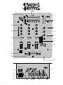 3
3
-
 4
4
-
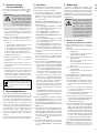 5
5
-
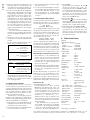 6
6
-
 7
7
-
 8
8
-
 9
9
-
 10
10
-
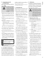 11
11
-
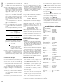 12
12
-
 13
13
-
 14
14
-
 15
15
-
 16
16
-
 17
17
-
 18
18
-
 19
19
-
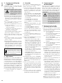 20
20
-
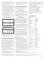 21
21
-
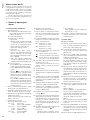 22
22
-
 23
23
-
 24
24
-
 25
25
-
 26
26


IMG STAGELINE MPX-30DMP Manuel utilisateur
- Catégorie
- Amplificateur d'instruments de musique
- Taper
- Manuel utilisateur
dans d''autres langues
- italiano: IMG STAGELINE MPX-30DMP Manuale utente
- English: IMG STAGELINE MPX-30DMP User manual
- español: IMG STAGELINE MPX-30DMP Manual de usuario
- Deutsch: IMG STAGELINE MPX-30DMP Benutzerhandbuch
- Nederlands: IMG STAGELINE MPX-30DMP Handleiding
- polski: IMG STAGELINE MPX-30DMP Instrukcja obsługi
Documents connexes
-
IMG STAGELINE MPX-20USB Manuel utilisateur
-
IMG STAGELINE MPX-44/SW Manuel utilisateur
-
IMG STAGELINE MMX-11USB Manuel utilisateur
-
IMG STAGELINE MPX-622/SW Manuel utilisateur
-
-
-
-
-
-
Autres documents
-
DJ-Tech DX3000USB Manuel utilisateur
-
IMG Stage Line MPX-44 Manuel utilisateur
-
Vonyx STM2500 Le manuel du propriétaire
-
 Power Dynamics 10031795 Le manuel du propriétaire
-
-
Fonestar SM-1860U Manuel utilisateur
-
Ecler nuo 2.0 Manuel utilisateur
-
Ecler NUO40 Manuel utilisateur
-
-
