Maytag MHN31PDAWW Installation Instructions Manual
- Catégorie
- Machines à laver
- Taper
- Installation Instructions Manual
Ce manuel convient également à

INSTALLATIqNiNSTRUCTiONS
COMMERCIALFRONT-LOADWASHER
iNSTRUCTiONSD'INSTALLATI
LAVEUSECOMMERCIALEACHARGEMENTFRONTAL
Table of Contents/Table des mati_res ........................................ 2
Models/ModUles
MHN31PDAWW, MHN31PDAXW,
MHN31 PRAWW and
MHP31 PRAWW
W10618412A
www.maytagcommerciallaundry.com

TABLEOFCONTENTS
WASHER SAFETY ................................................................................... 3
iNSTALLATiON REQUIREMENTS .......................................................... 4
Tools and Parts ..................................................................................... 4
Accessories .......................................................................................... 4
Options ................................................................................................. 4
Location Requirements ........................................................................ 5
Drain System ........................................................................................ 5
Electrical Requirements ........................................................................ 6
INSTALLATION INSTRUCTIONS ............................................................ 6
Remove Transport System ................................................................... 6
Connect the Inlet Hoses ....................................................................... 7
Connect the Drain Hose ....................................................................... 8
Secure the Drain Hose ......................................................................... 8
Level the Washer .................................................................................. 9
Installing Pad Strips ............................................................................. 9
Complete Installation ............................................................................ 9
USER & SET-UP INSTRUCTIONS ........................................................ 10
General User Information ................................................................... 10
Control Set-up Procedures ................................................................ 10
Start Operating Set-up ....................................................................... 10
WASHER CARE ..................................................................................... 14
Cleaning Your Washer ........................................................................ 14
Water Inlet Hoses ............................................................................... 14
ASSISTANCE OR SERVICE .................................................................. 14
WARRANTY ........................................................................................... 15
TABLEDESMATI#RES
SECURITI_ DE LA LAVEUSE ................................................................ 16
EXIGENCES D'INSTALLATION ............................................................ 17
Outillage et pi_ces .............................................................................. 17
Accessoires ........................................................................................ 17
Options ............................................................................................... 18
Exigences d'emplacement ................................................................. 18
Syst_me de vidange ........................................................................... 19
Sp6cifications 61ectriques .................................................................. 19
INSTRUCTIONS D'INSTALLATION ...................................................... 20
D6pose du syst_me de transport ....................................................... 20
Raccordement des tuyaux d'alimentation .......................................... 20
Raccordement du tuyau de vidange .................................................. 22
Immobilisation du tuyau de vidange .................................................. 22
R6glage de I'aplomb de la laveuse .................................................... 23
Installation des bandes de protection ................................................ 23
Achever I'installation .......................................................................... 23
INSTRUCTIONS DE CONFIGURATION ............................................... 24
Informations g6n6rales pour I'utilisateur ............................................ 24
Proc6dures de r6glage des syst_mes de commande ........................ 24
Param6trage pour mise en marche .................................................... 25
ENTRETIEN DE LA LAVEUSE .............................................................. 29
Nettoyage de la laveuse .................................................................... 29
Tuyaux d'arriv_e d'eau ....................................................................... 30
ASSISTANCE OU SERVICE .................................................................. 30
GARANTIE .................................................................. Couverture artiste
2

WASHERSAFETY
Your safety and the safety of others are very important,
We have provided many importantsafety messagesinthis manual and onyour appliance. Always readand obey all safety
messages.
This is the safety alert symbol.
This symbol alerts you to potential hazards that can kill or hurt you and others.
All safety messages will follow the safety alert symbol and either the word "DANGER" or "WARNING."
These words mean:
You can be kiUed or seriously injured if you don't imrnediately
follow instructions.
You can be killed or seriously injured if you don't follow
instructions.
All safety messages will tell you what the potential hazard is, tell you how to reduce the chance of injury, and tell you what can
happen ifthe instructions are not followed.
iMPORTANT SAFETY iNSTRUCTiONS
WARNING: To reduce the risk of fire, electric shock, or injury to persons when using the washer, follow basic
precautions, includingthe following:
[] Read all instructionsbefore using the washer.
[] Do not wash articles that have been previously
cleaned in, washed in, soaked in, or spotted with
gasoline, dry-cleaning solvents, other flammable,
or explosive substances as they give off vapors
that could ignite or explode.
[] Do not add gasoline, dry-cleaning solvents, or
other flammable, or explosive substances to the
wash water. These substances give off vapors
that could ignite or explode.
[] Under certain conditions, hydrogen gas may be
produced in a hot water system that has not been
used for 2 weeks or more. HYDROGEN GAS iS
EXPLOSIVE. if the hot water system has not
been used for such a period, before using the
washing machine, turn on all hot water faucets
and let the water flow from each for several
minutes. This will release any accumulated
hydrogen gas. As the gas is flammable, do not
smoke or use an open flame during this time.
Do not allow children to play on or in the washer. Close
supervision of children is necessary when the washer is
used near children.
Before the washer is removed from service or discarded,
remove the door or lid.
[] Do not reach into the washer if the drum, tub or agitator
is moving.
[] Do not install or store the washer where itwill be
exposed to the weather.
[] Do not tamper with controls.
[] Do not repair or replace any part of the washer or
attempt any servicing unless specifically recommended
in this manual or in published user-repair instructions
that you understand and have the skills to carry out.
[] See "Electrical Requirements" for grounding instructions.
SAVE THESE iNSTRUCTiONS
State of California Proposition 65 Warnings:
WARNING: This product contains one or more chemicals known to the State of California to cause cancer.
WARNING: This product contains one or more chemicals known to the State of California to cause birth defects or other
reproductive harm.
3

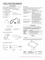
iNSTALLATiONREQUIREMENTS
Toolsand Parts
Gather the required tools and parts before starting installation.
The parts supplied are in the washer drum.
Tools needed for connecting the water inlet hoses
[] Pliers (that open to [] Flashlight (optional)
1 9/16"[39.5 mm])
Tools needed for installation
[] Open end wrenches [] Level
1/2" and 9/16"
[] Wood block
[] Torx T20 O1 Security [] Ruler or measuring tape
screwdriver
[] 1/4" nut driver
Parts supplied
A B C D
A. U-shaped hose form
B. Water inlet hoses (2)
C. Inlet hose washers (4)
D. Transit bolt hole plug (4)
E. Beaded tie strap
Parts supplied for PD Models:
Servicedoor lock cam
Foampads
Parts supplied for PR Models:
Card reader bezel
Cardreader wire Screws (2)
harness
Alternate Parts
Your installation may require additional parts. If you are interested
in purchasing one of the items listed here, call the toll-free
number in the "Assistance or Service" section.
if you have You will need to buy
Laundry tub or standpipe Sump pump system (if not already
taller than 96" (2.4 m) available)
Overhead sewer
Standard 20 gal. (76 L), 30"
(762 mm) tall drain tub or utility
sink and sump pump (available
from local plumbing suppliers)
Floor drain
Siphon break, Part Number
285834; additional drain hose,
Part Number 8318155; and
connector kit, Part Number 285835
Drain hose too short 4 ft (1.2 m) drain hose extension
kit, Part Number 285863
Water faucets beyond 2 longer water fill hoses:
reach of fill hoses 6 ft (1.am) Part Number 76314
10 ft (3.0m) Part Number 350008
Accessories
Enhance your washer with these premium accessories.
For more high-quality items or to order, call 1-800-901-2042, or
visit us at www.whir{pooLcom/accessories. In Canada call:
1-800-807-8777 or visit us at www.whirlpoo{parts.ca.
Part Number Accessory
8212526 Washer drip trays, fits under all
31682 All purpose appliance cleaner
1903WH Laundry supply storage cart
Options
Pedestal
You have the option of purchasing pedestals separately for this
washer. The pedestal will add to the total height of the washer.
Optional pedestal
Pedestal Approximate Color Part Number
Height height with washer
2 7/8"(73 mm) 47.5" (1207 mm) White WHP0400VW
®1TORXandT20 are registeredtrademarks of Acument Intellectual Properties, LLC.
4

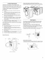
LocationRequirements
Selecting the proper location for your washer improves
performance and minimizes noise and possible washer "walk."
Your washer can be installed under a custom counter, or in a
basement, laundry room, or recessed area. See "Drain System."
Companion appliance location requirements should also be
considered. Proper installation is your responsibility.
You will need
[] A water heater set to deliver 120°F (49°C) water to the
washer.
[] A grounded electrical outlet located within 6 ft. (1.8 m)
of where the power cord is attached to the back of the
washer. See "Electrical Requirements."
[] Hot and cold water taps located within 4 ft. (1.2 m) of
the hot and cold water fill valves, and water pressure of
20-100 psi (137.9-689.6 kPa).
[] A level floor with a maximum slope of 1" (25 mm) under
entire washer. Installing the washer on soft floor surfaces,
such as carpets or surfaces with foam backing, is not
recommended.
[] A sturdy and solid floor to support the washer with a total
weight (water and load) of 400 Ibs (180 kg).
Do not operate your washer in temperatures below 32°F (0°C).
Some water can remain in the washer and can cause damage
in low temperatures.
Installation clearances
[] The location must be large enough to allow the washer
door to be fully opened.
[] Additional spacing should be considered for ease of
installation and servicing. The door opens more than 90°,
and it is not reversible.
[] Additional clearances might be required for wall, door, and
floor moldings.
[] Additional spacing of 1" (25 mm) on all sides of the washer
is recommended to reduce noise transfer.
[]
Companion appliance spacing should also be considered.
Washer Dimensions
A floor drain should be provided under the bulkhead.
Prefabricated bulkheads with electrical outlets, water inlet lines,
and drain facilities should be used only where local codes permit.
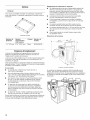
DrainSystem
The washer can be installed using the standpipe drain system
(floor or wall), the laundry tub drain system, or the floor drain
system. Select the drain hose installation method you need.
See "Tools and Parts."
Standpipe drain system - waNIor floor (views A & B}
The standpipe drain requires a minimum diameter standpipe of
2" (50 mm). The minimum carry-away capacity can be no less
than 12 gal. (45.5 L) per minute, per washer.
The top of the standpipe must be at least 30" (762 mm) high and
no higher than 96" (2.4 m) from the bottom of the washer.
1
30"min.
(762mm)
! ..........
50 1/2"
44 5/6"
(1134 ram)
/
A B
Laundry tub drain system
The laundry tub needs a minimum 20 gal. (76 L) capacity. The top
of the laundry tub must be at least 30" (762 mm) above the floor.
28 13/16"
(732 mm)
Door is not reversible
5

Floor drain system
The floor drain system requires a siphon break that may be
purchased separately. See "Tools and Parts."
The siphon break must be a minimum of 28" (710 mm) from the
bottom of the washer. Additional hoses might be needed.
Back view
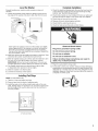
ElectricalRequirements
Electrical Shock Hazard
Plug into a grounded 3 prong outlet.
Do not remove ground prong.
Do not use an adapter.
Do not use an extension cord.
Failure to follow these instructions can result in
death, fire, or electrical shock.
[] A 120 volt, 60 Hz., AC only, 15- or 20-amp, fused electrical
supply is required. A time-delay fuse or circuit breaker is
recommended. It is recommended that a separate circuit
serving only this washer be provided.
[] This washer is equipped with a power supply cord having
a 3 prong grounding plug.
[] To minimize possible shock hazard, the cord must be
plugged into a mating, 3 prong, grounding-type outlet,
grounded in accordance with local codes and ordinances.
If a mating outlet is not available, it is the personal
responsibility and obligation of the customer to have the
properly grounded outlet installed by a qualified electrician.
[] If codes permit and a separate ground wire is used, it is
recommended that a qualified electrician determine that the
ground path is adequate.
[] Do not ground to a gas pipe.
[] Check with a qualified electrician if you are not sure the
washer is properly grounded.
[] Do not have a fuse in the neutral or ground circuit.
GROUNDING iNSTRUCTiONS
For a grounded, cord=connected washer:
This washer must be grounded, in the event of a malfunction
or breakdown, grounding will reduce the risk of electrical
shock by providing a path of least resistance for electric
current. This washer is equipped with a cord having an
equipment=grounding conductor and a grounding plug.
The plug must be plugged into an appropriate outlet that is
properly installed and grounded in accordance with all local
codes and ordinances.
WARNING: Improper connection of the equipment-
grounding conductor can result in a risk of electric shock.
Check with a qualified electrician or serviceman if you are
in doubt as to whether the appliance is properly grounded.
Do not modify the plug provided with the appliance - if it will
not fit the outlet, have a proper outlet installed by a qualified
electrician.
For a permanently connected washer:
This washer must be connected to a grounded metal,
permanent wiring system, or an equipment grounding
conductor must be run with the circuit conductors and
connected to the equipment=grounding terminal or lead
on the appliance.
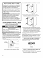
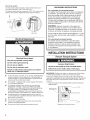
iNSTALLATiONiNSTRUCTiONS
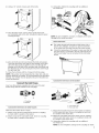
RemoveTransport System
Excessive Weight Hazard
Use two or more people to move and install washer.
Failure to do so can result in back or other injury.
iMPORTANT: Position the washer so that the rear of the washer
is within approximately 3 ft. (900 mm) of its final location.
There are 4 shipping bolts in the rear panel of the washer that
support the suspension system during transportation. These bolts
also retain the power cord inside the washer until the bolts are
removed.
1. Keep the washer in the upright position while removing the
shipping bolts.
Shipping bolt
Shipping bolt with plastic spacer
6

2. Using a 1/2" wrench, loosen each of the bolts.
3. Once the bolt is loose, move it to the center of the hole
and completely pull out the bolt, including the plastic spacer
covering the bolt.
3. Using pliers, tighten the couplings with an additional
two-thirds turn.
NOTE: Do not overtighten, use tape, or sealants on the valve.
Damage to the valves can result.
Clear water lines
[] Run water through both faucets and inlet hoses, into a
laundry tub, drainpipe, or bucket, to get rid of particles
in the water lines that might clog the inlet valve screens.
[] Check the temperature of the water to make sure that the
hot water hose is connected to the hot water faucet and
that the cold water hose is connected to the cold water
faucet.
4. Once all 4 bolts are removed, discard the bolts and spacers.
Then push the power cord plug into the opening on the right
side of the rear panel and pull the power cord through the
opening on the left side of the rear panel and close holes with
the attached cap. Do not pull plug end of power cord through
the right side hole.
5. Close the bolt holes with the 4 transport bolt hole plugs.
NOTE: If the washer is to be transported at a later date, call your
product distributor or installer. To avoid suspension and structural
damage, your washer must be properly set up for relocation by a
trained professional.
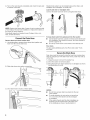
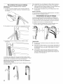
Connectthe Inlet Hoses
Insert new flat washers (supplied) into each end of the inlet
hoses. Firmly seat the washers in the couplings.
A B
A. Coupling
B. Washer
Connect the inlet hoses to water faucets
Make sure the washer drum is empty.
1. Attach a hose to the hot water faucet. Screw on coupling
by hand until it is seated on the washer.
2. Attach a hose to the cold water faucet. Screw on coupling
by hand until it is seated on the washer.
Connect the inlet hoses to the washer
1=
2=
3=
¢
C. Cold water inlet
H. Hot water inlet
Attach the hot water hose to the check valve on washer's
hot (H) water inlet valve. Screw on coupling by hand until
it is seated on the check valve.
Attach the cold water hose to the check valve on washer's
cold (C) water inlet valve. Screw on coupling by hand until
it is seated on the check valve.
Using pliers, tighten the couplings with an additional
two-thirds turn.
NOTE: Do not overtighten. Damage to the coupling can result.
7

4. Turn on the water faucets completely and check for leaks and
at washer connection.
0
66
NOTE: Replace inlet hoses after 5 years of use to reduce the risk
of hose failure. Record hose installation or replacement dates on
the hoses for future reference.
Periodically inspect and replace hoses if bulges, kinks, cuts,
wear, or leaks are found.
Connectthe DrainHose
Remove drain hose from washer drum
1. Use locking pliers, squeeze hose clamp tabs together and
insert over the end of drain hose.
2. Slide drain hose onto washer connection.
3. Once drain hose is in place, release pliers.
Washer drain system can be installed using a floor drain, wall
standpipe, floor standpipe, or laundry tub.
Laundry tub drain or standpipe drain
Connect the drain hose form to the corrugated drain hose.
To keep drain water from going back into the washer:
[] Use the drain hose form, and do not force excess drain hose
into standpipe. Hose should be secure, but loose enough to
provide a gap for air.
[] Do not lay excess hose on the bottom of the laundry tub.
Floor drain
You may need additional parts. See Floor drain under "Tools
and Parts."
Securethe DrainHose
Drain hose must be secured to stop the hose from moving when
water is pumped out. If the drain hose moves, water may end up
on the floor.
1. Drape the power cord over the washer top.
2. Move the washer to its final location.
3. Place the drain hose in the laundry tub or standpipe as shown.
See illustrations A and B.
A B C
t
4½"
(114mm)
NOTES:
[] Do not force excess drain hose back into the rear
of the washer.
[] To avoid siphoning, do not seal or put more than
4 1/2"(114 mm) of the drain hose into drainpipe
or standpipe.
[] If the washer faucets and the drain standpipe are
recessed, put the hooked end of the drain hose
in the standpipe as shown. See illustration C.
8

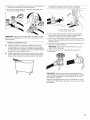
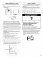
Level the Washer
Properly leveling your washer avoids excessive noise and
vibration.
1. Check the levelness of the washer by placing a level on the
top edge of the washer, first side to side, then front to back.
I
If the washer is against a wall, move the washer out slightly
before tipping back. If the washer is not level, first prop the
front with a wood block and adjust the feet as necessary;
then prop the back and adjust feet as necessary. Repeat this
step until washer is level.
2. Make sure all four feet are stable and resting on the floor. Then
check that the washer is perfectly level (use a level).
3. After the washer is level, use a 9/16" open-end wrench to turn
the nuts on the feet tightly against the washer cabinet.
IMPORTANT: All four feet must be tightened. If the nuts are
not tight against the washer cabinet, the washer may vibrate.
4. The washer should not move front to back, side to side,
or diagonally when pushed on its top edges.
5. Slide the washer to its final location.
6. Confirm the levelness of the washer.
Installing PadStrips
NOTE: For PD Models only.
1. Take the 2 foam pad strips from bag.
2. Remove tape from the back of adhesive pads.
3. Install the pads on the left and right inside walls of the coin
vault, leaving about 1/4" (6 mm) to 1/2" (13 mm) of space near
the front edge of the vault to allow room for the coin box to
lock into position.
7A
Complete Installation
1. Check the electrical requirements. Be sure that you have the
correct electrical supply and the recommended grounding
method. See "Electrical Requirements."
2. Check that all parts are now installed. Ifthere is an extra part,
go back through the steps to see which step was skipped.
3. Check that you have all of your tools.
4. Dispose of/recycle all packaging materials.
5. Check that the water faucets are on.
6. Check for leaks around faucets and inlet hoses.
7=
8.
Electrical Shock Hazard
Plug into a grounded 3 prong outlet.
Do not remove ground prong.
Do not use an adapter.
Do not use an extension cord.
Failure to follow these instructions can result in
death, fire, or electrical shock.
Plug into a grounded 3 prong outlet.
To test and to clean your washer, measure 1/2 the detergent
manufacturer's recommended amount of High Efficiency (HE)
detergent for a medium-size load. Pour the detergent into the
detergent dispenser. Select any cycle and allow the washer to
complete one whole cycle.
A. Foam pad strips
9

USER&SET-UPiNSTRUCTiONS
WHITES COLORS BRIGHTS
PERM. WOOLENS DEMCATES
PRESS AND KNITS
NOTE: After the washer has been installed and plugged in, the
display may show '0 MINUTES'. Once the washer has been
plugged in and the washer door opened and closed, the display
will show the price. In washers set to $0.00 vend price, the
display will flash 'SELECT CYCLE' instead of a vend price. Note,
however, that the PR models will require a Smart Card to enable
a cycle.
1. PD Models: Insert coins until 'SELECT CYCLE' flashes in
display.
PR Models: A debit card is required rather than coins. In
Enhanced Debit mode, the card balance will also display
when a debit card is inserted into the reader.
2. Door must be closed before cycle selection is made,
3. Press fabric setting button for the wash cycle desired. After
the cycle is started, the time will display and count down.
4. If a cycle is interrupted by opening the door, 'RESELECT
CYCLE' will flash in the display. To restart the washer, close
door, and reslect desired cycle.
GeneralUserInformation
SCROLLING 'OUT OF ORDER' SHOWING IN DISPLAY
This condition indicates the washer is inoperative.
'0 MINUTES' SHOWING IN DISPLAY
This indicates the cycle is complete and the washer cannot be
operated. Coins dropped or debit inputs during this condition will
be stored in escrow but cannot be used until normal operation is
restored by opening and closing the door. If a door switch fails, it
must be replaced before normal operation can be restored.
COLD START (initial first use)
Washer is programmed at the factory as follows:
11-minute wash period
3 rinses (extra rinse not enabled)
7 x coin 1 wash price (PD models)
WARM START (after power failure)
A few seconds after power isrestored, ifa cycle was in progress at
the time of the power failure, 'RESELECT CYCLE' will flash in the
display, indicating the need for a key press to restart washer.
DOOR LOCK
Prior to beginning a cycle, there isa door lock routine of lock/unlock/
relock then cycle begins. The door will remain locked until the end of
a cycle or approximately 2 minutes after a power interruption.
PRICING
After the door is opened following the completion of a cycle, the
display indicates the cycle price (unless set to $0.00 Vend). As
coins are dropped or debit inputs arrive, the display will change to
lead the user through the initiation of a cycle.
FREE CYCLES
The PR models require a valid form of payment (or vend) to start a
cycle, even if the amount is set at $0.00 (see $0.00 Vend below).
$0.00 VEND
The PR models require a valid form of payment (or vend) to start a
cycle, even if the amount is set at $0.00.
In this mode, the washer must be equipped with a debit card reader
and the cycle price set to $0.00. The user must have a valid Smart
Card to start a cycle, although no value will be deducted from
the card.
DEBIT CARD READY
This washer is debit card 'cable' ready. It will accept a variety of
debit card systems, but does NOT come with a debit card reader.
Refer to the debit card reader manufacturer for proper washer
set-up. In models converted to a Generation 1 debit card system,
debit pulses represent the equivalent of one coin (coin 1).
DISPLAY
After the washer has been installed and plugged in, the display
may show '0 MINUTES'. Once the washer has been plugged in
and the washer door opened and closed, the display will show
the vend price. In washers set for $0.00 Vend, the display will
flash 'SELECT CYCLE' and the PR Model will require a Smart
Card to enable a cycle.
ControJ Set-up Procedures
IMPORTANT: Read all instructions before operating.
PD Models: insert access door key, turn, and lift to remove access
door.
PR Models: Once the debit card reader is installed (according
to the reader manufacturer's instructions), the set-up mode can
only be entered by inserting a set-up card (supplied by the reader
manufacturer) into the card slot.
The lower fabric setting buttons and the digital display are used to
set up the controls.
The display can contain 4 numbers and/or letters and a decimal
point. These are used to indicate the set-up codes and related
code values available for use in programming the washer.
HOW TO USE THE BUTTONS TO PROGRAM THE CONTROLS
1. The PERM PRESS button is used to adjust the values
associated with set-up codes. Pressing the button will change
the value by increments. Rapid adjustment is possible by
holding the button down.
2. The WOOLENS button will advance through the set-up codes.
Pressing the button will advance to the next available set-up
code. Holding the button down will automatically advance
through the set-up codes at a rate of 1 per second.
3. The DELICATES AND KNITS button is used to select or
deselect options.
Start Operating Set-up
Washers are preset at the factory for an 11-minute wash period
and 3 rinses (no extra rinse).
SET-UP CODES
[] The WOOLENS button will advance you from code to code.
[] The PERM PRESS button will change the code value.
[] The DELICATES AND KNITS button will select or deselect
options.
FOR PR MODELS: The set-up codes are the same as for the
"PD" model except where noted.
The set-up code is indicated by the one or two left-hand
characters. The set-up code value is indicated by the two or
three right-hand characters.
10

CODE EXPLANATION
6 07 REGULAR CYCLE PRICE (Factory Defau}t)
6 07 Represents the number of quarters (coin 1);
may adjust from 0-39. (See VALUE OF COiN 1.)
Advance from 0-39 by pressing the PERM PRESS
button. Factory default of 7 quarters = $1.75.
6 00 PR MODELS ONLY: Factory default of 0 quarters.
6 01 setting would represent one coin slide
actuation.
Press the WOOLENS button once to advance to
next code.
7 11 WASH LENGTH
7 11 This is the number of minutes for WASH. Washer
comes from the factory preset with 11 minutes.
Choose from 9-17 minutes by pressing the PERM
PRESS button.
Press the WOOLENS button once to advance to
next code.
t
8 00 ADDITIONAL RINSE OPTION
This option is either SELECTED 'ON' or NOT
SELECTED 'OFF'.
8 00 Not Selected 'OFF'.
8 Ar Selected 'ON'. Cannot be combined with the
Super Cycle rinse option.
Press the DELICATES AND KNITS button once for
this selection.
--> Press the WOOLENS button once to advance to
next code.
9 00 CYCLE COUNTER OPTION
This option is either SELECTED 'ON' or NOT
SELECTED 'OFF'.
9 00 Not Selected 'OFF'.
9 0C Selected 'ON' and not able to be deselected.
Press the DELICATES AND KNITS button 3
consecutive times to select 'ON'. Once selected
'ON' it cannot be deselected.
--> Press the WOOLENS button once to advance to
next code.
1. 00 MONEY COUNTER OPT{ON
This option is either SELECTED 'ON' or NOT
SELECTED 'OFF'.
1. 00 Not Selected 'OFF'.
1. 0C Selected 'ON'.
Press the DELICATES AND KNITS button
3 consecutive times to select 'ON' and 3
consecutive times to remove (Not Selected 'OFF'.)
Counter resets by going from 'OFF' to 'ON'.
1 CO Selected 'ON' and not able to be deselected.
To select 'ON' and not able to be deselected,
first select 'ON', then within 2 seconds, press
the DELICATES AND KNITS twice, PERM PRESS
once, and exit the set-up mode.
Press the WOOLENS button once to advance to
next code.
t, t
2. 00 SPECIAL PRICING OPTIONS
This option is either SELECTED 'ON' or NOT
SELECTED 'OFF'.
2. 00 Not Selected 'OFF', and next available code will
be A.00.
2. SP Selected 'ON'. Press the DELICATES AND KNITS
button once for this selection.
CODE EXPLANATION
if SPECIAL PRiCiNG OPTION is selected, there is access
to codes '3.XX' through '9.XX'.
--y Press the WOOLENS button once to advance to
next code.
Options to use if SPECIAL PRICING is selected:
3. 07 SPECIAL CYCLE PRICE
3. 07 Represents the number of quarters (coin 1); may
adjust from 0-39. (See VALUE OF COiN 1.)
Advance from 0-39 by pressing the PERM PRESS
3. 00 button. Factory default of 7 quarters = $1.75
PR MODELS ONLY: Factory default of 0 quarters.
-> Press the WOOLENS button once to advance to
next code.
5. 00 TIME-OF-DAY CLOCK, M{NUTES
5. 00 This is the TIME-OF-DAY CLOCK, minute setting;
select 0-59 minutes by pressing the PERM
PRESS button.
Press the WOOLENS button once to advance to
next code.
6. 00 TIME-OF-DAY CLOCK, HOURS
NOTE: Uses MiLiTARY TIME or 24 hr. clock
6. 00 This is the TIME-OF-DAY CLOCK, hour setting;
select 0-23 hours by pressing the PERM PRESS
button.
Press the WOOLENS button once to advance to
next code.
7. 00 SPECIAL PRICE START HOUR
NOTE: Uses MILITARY TIME or 24 hr. clock
r
7. 00 This is the start hour; 0-23 hours. Select START
HOUR by pressing the PERM PRESS button.
--> Press the WOOLENS button once to advance to
next code.
........................................ r ; rr_
8. 00 SPECIAL PRICE STOP HOUR
NOTE: Uses MILITARY TIME or 24 hr. clock
r ; r; r; r; r .............................r; r ; r; r; r; r; r r r r r
8. 00 This is the stop hour; 0-23 hours. Select STOP
HOUR by pressing the PERM. PRESS button.
--> Press the WOOLENS button once
to advance to next code.
Jr rJ r i J J i J ;
9. 10 SPECIAL PRICE DAY
r J r r J r rJ r J r r J r Jl r r J r J r r r
9. 10 This represents the day of the week and whether
special pricing is selected for that day. A number
followed by '0' indicates no selection that
particular day (9.10). A number followed by an'S'
indicates selected for that day (9.1S). To change
the value of '0' and 'S', use the DELICATES AND
KNITS button.
Days of the week (1-7) are selected by pressing
the PERM PRESS button.
When exiting set-up code '9', the display must
show current day of week:
-->
DISPLAY DAY OF WEEK CODE (selected)
10 Day 1 = Sunday 1S
20 Day 2 = Monday 2S
30 Day 3 = Tuesday 3S
40 Day 4 = Wednesday 4S
50 Day 5 = Thursday 5S
60 Day 6 = Friday 6S
70 Day 7 = Saturday 7S
Press the WOOLENS button once to advance to
next code.
11

CODE EXPLANATION
A. 00 VAULT ViEWiNG OPTION
This option is either SELECTED 'ON' or NOT
SELECTED 'OFF'.
A. 00 Not Selected 'OFF'.
A. SC Selected 'ON'. Press the DELICATES AND KNITS
button once for this selection. When selected, the
money and/or cycle counts will be viewable (if
counter option(s) is selected) when the coin box is
removed.
---> Press the WOOLENS button once to advance to
next code.
b. 05 VALUE OFCOIN 1
r
b. 05 This represents the value of coin 1 in number of
nickels: 05 = $0.25.
By pressing the PERM PRESS button, there is a
option of 1-199 nickels.
--> Press the WOOLENS button once to advance
to next code.
C. 20 VALUE OF COIN 2
rJ Jr
C. 20 This represents the value of coin 2 in number of
nickels: 20 = $1.00.
C. 05 PR MODELS ONLY: Factory default of $0.25 By
pressing the PERM PRESS button, there is the
option of 1-199 nickels.
--> Press the WOOLENS button once to advance to
next code.
r
d. 00 COIN SLIDE OPTION
This option is either SELECTED 'ON' or NOT
SELECTED 'OFF'. Replacement of meter case will
be needed for coin slide mounting.
d. 00 Not Selected 'OFF'.
d. CS
Selected 'ON'. NOTE: This option needs to be
set to "00" unless the meter case has been
changed to accept a coin slide device. Press the
DELICATES AND KNITS button 3 consecutive
times for this selection.
When coin slide mode is selected, set 'b'. equal
to value of vend price in nickels. Set set-up
code 6 xx (regular cycle price) and set-up code
3.xx (special cycle price) to number of slide
operations. If the installer sets-up 'CS' and a coin
drop mechanism is installed, the washer will not
register coins that are inserted.
Press the WOOLENS button once to advance to
next code.
ADD COINS OPTION
E.
This option is either SELECTED 'ON' or NOT
SELECTED 'OFF'. This option causes the
customer display to show the number of coins
(coin 1) to enter, rather than the dollars-and-cents
amount.
00 Not Selected 'OFF'.
E. AC Selected 'ON'. Press the DELICATES AND KNITS
button 3 consecutive times for this selection.
-->
Press the WOOLENS button once to advance to
next code.
CODE EXPLANATION
F. 00 ENHANCED PRiCiNG OPTION
F. 00 Not Selected 'OFF'.
R CP Cycle-Based pricing enabled. This option allows
configuration of different prices for cold, warm,
and hot water cycles.
R Su Super Cycle pricing enabled. This option allows
customers to upgrade cycles by depositing
extra money. Set-up codes "H." and "h." will be
displayed only when this option is enabled. Press
the DELICATES AND KNITS button once for this
selection.
--> Press the WOOLENS button once to advance to
next code.
___________________________________________________________________________________________________________________________________________r
m. 01 SUPER CYCLE UPGRADE PRICE
(Skipped unless super cycle pricing is enabled.)
i
H. 01 This represents the number of coin 1 required to
upgrade a base cycle to a super cycle. Advance
from 0-39 by pressing the PERM PRESS button.
--> Press the WOOLENS button once to advance to
next code.
h. 01 SUPER CYCLE TYPE
(Skipped unless Super Cycle pricing is enabled.)
r J; r J r J J Jr
h. 01 This represents the Super Cycle upgrade option.
Press the PERM. PRESS button to step through
upgrade options 1 through 3 as follows:
01 - enhanced wash, extra 3 minutes of wash
tumble in addition to the programmed wash time.
02 - extra rinse for all cycles.
03 - both 01 and 02.
--> Press the WOOLENS button once to advance to
next code.
J. Cd COIN/DEBIT OPTION
r r r; r; r; ...............................; r r r ..............................................................................................................
J. Cd Both coin and debit selected. Press the
DELICATES AND KNITS button 3 consecutive
times for this selection.
J. C Coins selected, debit disabled. Press the
DELICATES AND KNITS button 3 consecutive
times for this selection.
J. d PR models factory default to J.d. Debit Card
selected, coins disabled. Press the DELICATES
AND KNITS button 3 consecutive times for this
selection.
J. Ed Enhanced Debit is self-selected when a
Generation 2 card reader is installed in the
washer. The Ed option cannot be manually
selected or deselected.
-e Press the WOOLENS button once to advance to
next code.
r r;...........................................;i r; r r; r r r
L. 00 PRICE SUPPRESSION OPTION
This option causes the customer display to show
'ADD' or 'AVAILABLE' rather than the amount of
money to add. (Used mainly in debit installations.)
r r; r .................................... r
L. 00 Not Selected 'OFR'
L. PS Selected 'ON.' Press the QUICK CYCLE button
once for this selection.
--> Press the WOOLENS button once to advance to
next code.
¢ r rJ rJ
n. CE CLEAR ESCROW OPTION
When selected, money held in escrow for
30 minutes without further escrow or cycle
activity will be cleared.
12

CODE EXPLANATION
n 00 Not Selected 'OFF'.
n CE Selected 'ON'. Press the QUICK CYCLE button
once for this selection.
--> Press the WOOLENS button once to advance to
next code.
r. 800
r. 800
-->
U. O0
U. O0
A1. 00
TOP SPiN SPEED RPM
This can be selected from the following spin
speeds: 600 rpm, 750 rpm, 800 rpm, 1000
(displays as 999) rpm. Step between speeds by
pressing the PERM PRESS button. Factory
default of 800 rpm.
Press the WOOLENS button once to advance to
next code.
PENNY iNCREMENT OFFSET
This represents the penny increment price offset
used in Generation 2 (Enhanced Debit) PR
models. Choose from 0-4 pennies by pressing the
PERM PRESS button.
Press the WOOLENS button once to advance to
next code.
PREWASH LENGTH
Choose 0 to disable the prewash or select
between 2 and 7 minutes by pressing the PERM
PRESS button.
--> Press the WOOLENS button once to advance to
next code.
A2. 03 FINAL SPiN LENGTH
A2. 03 This is the number of minutes of final high speed
spin. Choose from 3-8 minutes by pressing the
PERM PRESS button.
--> Press the WOOLENS button once to advance to
next code.
If cycle counter (9 0C) is selected, the following is true:
1 00 Represents the number of 1 02 = 200
cycles in HUNDREDS
2 00 Represents the number of 2 25 = 25
cycles in ONES
TOTAL CYCLES = 225
This is "VIEW ONLY" and cannot be cleared.
Press the WOOLENS button once to advance to next code.
if money counter (1.00 or 1.00) is selected, the following
is true:
3 O0
Number of dollars in 3 01 = $100.00
HUNDREDS
4 00 Number of dollars in ONES 4 68 = $ 68.00
5 00 Number of CENTS 5 7.5 = $ .75
TOTAL = $168.75
END OF SET-UP PROCEDURES
EXiT FROM SET-UP MODE
PD Models: Reinstall access door.
PR Model: Remove manual set-up cards.
13

WASHERCARE
Cleaning YourWasher
Cleaning the Door Seal/Bellow
1. Open the washer door and remove any clothing or items from
the washer.
2. Inspect inner glass door. If debris is present, wipe off debris
using damp cloth.
3. Inspect the colored seal/bellow between the door opening
and the drum for stained areas. Pull back the seal/bellow to
inspect all areas under the seal/bellow and to check for for-
eign objects.
A. Seal/Bellow
4. If stained areas are found, wipe down these areas of the seal/
bellow, using the procedure that follows.
a} Mix a dilute solution, using 3/4 cup (177 mL) of liquid
chlorine bleach, and 1 gal. (3.8 L) of warm tap water.
b} Wipe the seal/bellow area with the dilute solution,
using a damp cloth.
c} Let stand 5 minutes.
d} Wipe down area thoroughly with a dry cloth and let the
washer interior air dry with door open.
IMPORTANT:
[] Wear rubber gloves when cleaning for prolonged periods.
[] Refer to the bleach manufacturer's instructions for proper use.
Washer Maintenance Procedure
This washer has a special cycle that uses higher water volumes
in combination with liquid chlorine bleach to thoroughly clean the
inside of the washer.
NOTES:
[] Read these instructions completely before beginning the
cleaning process.
[] If necessary, the cleaning cycle may be interrupted by
pressing the DELICATES AND KNITS button twice. However,
this will not immediately stop the cycle. The washer will
continue with several rinse and drain steps to ensure that all
remaining bleach is rinsed from the washer.
Begin procedure
1. Open the washer door and remove any clothing or items from
the washer.
2. Use liquid chlorine bleach:
Open the dispenser drawer and immediately add
2/3 cup (160 mL) of liquid chlorine bleach to the bleach
compartment.
NOTE: Do not add any detergent to this cycle. Use of more
than 2/3 cup (160 mL) of bleach will cause product damage
over time.
3. Close the washer door and the dispenser drawer.
4. To start the Clean Washer cycle, first enter "Start Operating
Set-up." Then press and hold DELICATES AND KNITS for
1 second. With the entire display flashing, press BRIGHTS.
NOTE: The drum will rotate, then the door will unlock, lock
again, and then the cycle will continue.
[] The washer will not fill, but the drum will rotate while
the washer runs a short sensing cycle. This will take
approximately 3 minutes.
5. The cycle will determine whether clothing or other items are
in the washer.
a} If no items are detected in the washer, it will proceed
to Step 7.
b} If any items are detected in the washer, "rL" or "F-34"
will be displayed. Then the door will unlock.
[] Press DELICATES AND KNITS to cancel the failure code.
Then repeat steps 1,3, and 4 to start the cycle again.
6. Once the cycle has begun, allow the cycle to complete.
7. After the cycle is complete, leave the door open slightly,
to allow for better ventilation and drying of washer interior.
Always do the following to maintain washer freshness
[] Use only "HE" High Efficiency detergent.
[] Leave the door slightly open after each cycle to allow
for better ventilation and drying of washer interior.
[] Clean the washer monthly using the Washer Maintenance
Procedure, and 2/3 cup (160 mL) of liquid chlorine bleach.
[] If the procedure does not sufficiently improve the machine
freshness, please evaluate your installation and usage
conditions for other causes.
r
Cleaning the exterior
r;
Use a soft damp cloth or sponge to wipe up any spills.
Occasionally wipe the outside of your washer to keep it looking
new. Use mild soap and water. Do not use abrasive products.
, ; r r;
C_eaning the dispenser drawer
r; ..................................................................................... r
The dispenser drawer is removable for easy cleaning.
1. Unlock the dispenser drawer by pressing the Release Lever.
Remove the drawer.
2. Remove the inserts (the siphon from the softener and bleach
compartments).
3. Wash the parts under running water.
NOTE: Do not wash components in the dishwasher.
4. Re-install the inserts and return the dispenser to the drawer.
Water Inlet Hoses
Replace water inlet hoses after 5 years of use to reduce the risk
of hose failure. Periodically inspect and replace water inlet hoses
if bulges, kinks, cuts, wear, or leaks are found.
When replacing your water inlet hoses, mark the date of
replacement on the label with a permanent marker.
ASSISTANCEORSERVICE
if you need assistance:
Contact the distributor where the washer was purchased from
or visit www.maytagcommerciallaundry.com.
When you call, have the washer model number and serial
number. Both numbers can be found on the serial-rating plate
located on your washer.
14

MAYTAG ® COMMEKCIAL SINGLE-LOAD AND VENDED
MULTI-LOAD WASHEK & DKYEK
WAK NTY
LiMiTED WARRANTY ON PARTS
For the first five years from the date of purchase, when this commercial appliance is installed, maintained and operated according to the
instructions attached to or furnished with the product, Maytag brand of Whirlpool Corporation (thereafter "Maytag") will pay for factory
specified parts or original equipment manufacturer parts to correct defects in materials or workmanship. Proof of original purchase date
is required to obtain service under this warranty.
ITEMS MAYTAG WiLL NOT PAY FOR
1. All other costs including labor, transportation, or custom duties.
2. Service calls to correct the installation of your commercial appliance, to instruct you how to use your commercial appliance, to
replace or repair fuses, or to correct external wiring or plumbing.
3. Repairs when your commercial appliance is used for other than normal, commercial use.
4. Damage resulting from improper handling of product during delivery, theft, accident, alteration, misuse, abuse, fire, flood, acts of
God, improper installation, installation not in accordance with local electrical or plumbing codes, or use of products not approved
by Maytag.
5. Pickup and Delivery. This commercial appliance is designed to be repaired on location.
6. Repairs to parts or systems resulting from unauthorized modifications made to the commercial appliance.
7. The removal and reinstallation of your commercial appliance if it is installed in an inaccessible location or is not installed in
accordance with published installation instructions.
8. Chemical damage is excluded from all warranty coverage.
9. Changes to the building, room, or location needed in order to make the commercial appliance operate correctly.
10. Repairs made by a non-Whirlpool authorized service technician.
DISCLAIMER OF iMPLIED WARRANTIES; LiMiTATIONS OF REMEDIES
CUSTOMER'S SOLE AND EXCLUSIVE REMEDY UNDER THIS LIMITED WARRANTY SHALL BE PRODUCT REPAIR AS PROVIDED
HEREIN. IMPMED WARRANTIES, INCLUDING WARRANTIES OF MERCHANTABILITY OR FITNESS FOR A PARTICULAR PURPOSE,
ARE LIMITED TO ONE YEAR OR THE SHORTEST PERIOD ALLOWED BY LAW. WHIRLPOOL SHALL NOT BE LIABLE FOR
INCIDENTAL OR CONSEQUENTIAL DAMAGES. SOME STATES AND PROVINCES DO NOT ALLOW THE EXCLUSION OR LIMITATION
OF INCIDENTAL OR CONSEQUENTIAL DAMAGES, OR LIMITATIONS ON THE DURATION OF IMPUED WARRANTIES OF
MERCHANTABIMTY OR FFNESS, SO THESE EXCLUSIONS OR MMITATIONS MAY NOT APPLY TO YOU. THIS WARRANTY GIVES
YOU SPECIFIC LEGAL RIGHTS AND YOU MAY ALSO HAVE OTHER RIGHTS, WHICH VARY FROM STATETO STATE OR PROVINCE
TO PROVINCE.
If you need service, please contact your authorized Maytag ® Commercial Laundry distributor. To locate your authorized Maytag ®
Commercial Laundry distributor, or for web inquiries, visit www.MaytagCommercialLaundry.com.
3/10
For written correspondence:
Maytag ® Commercial Laundry Service Department
2000 M-63 North
Benton Harbor, Michigan 49022 USA
15

SI CURITI DU LAVEUSE
Votre s_curit_ et celle des autres est tr_s importante.
Nous donnons de nombreux messages de securit6 importants dans ce manuel et sur votre appareil menager. Assurez-vous de
toujours lire tousles messages de s6curit6 et de vous y conformer.
Voici le symbole d'alerte de securit6.
Ce symbole d'alerte de s6curit6 vous signale les dangers potentiels de d6c_s et de blessures graves &vous
et & d'autres.
Tousles messages de s6curit_ suivront le symbole d'alerte de s6curit6 et le mot "DANGER" ou
"AVERTISSEMENT'. Ces mots signifient :
Risque possible de d_c_s ou de blessure grave si vous ne
suivez pas imm6diatement les instructions.
Risque possible de d_c_s ou de blessure grave si vous
ne suivez pas les instructions.
Tousies messages de s6curit6 vous diront quel est le danger potentiel et vous disent comment r_duire le risque de blessure et
ce qui peut se produire en cas de non-respect des instructions.
IMPORTANTES iNSTRUCTiONS DE SECURITI_
AVERTISSEIVIENT : Pour r6duire les risques d'incendie, de choc electrique ou de blessures Iors de I'utilisation de la
laveuse, suivre les precautions fondamentales dont les suivantes :
[] Lire toutes les instructions avant d'utiliser la laveuse.
[] Ne pas laver des articles qui ont 6t6 nettoy6s ou
lav6s avec de I'essence ou imbib6s d'essence,
solvants de nettoyage & sec, ou autres substances
inflammables ou explosives; ces substances
peuvent 6mettre des vapeurs susceptibles de
s'enflammer ou d'exploser.
[] Ne pas ajouter d'essence, solvant de nettoyage &
sec ou autre produit inflammable ou explosif dans
I'eau de lavage. Ces substances peuvent 6mettre
des vapeurs susceptibles de s'enflammer ou
d'exploser.
[] Darts certaines conditions, de I'hydrog6ne gazeux
peut se former dans un circuit d'eau chaude qui n'a
pas 6t6 utilis6 pendant 2 semaines ou plus. LE GAZ
HYDROG#NE EST EXPLOSIBLE. Si le circuit d'eau
chaude n'a pas 6t6 utilis6 pendant une telle p6riode,
avant d'utiliser la laveuse, ouvrir tousles robinets
d'eau chaude et laisser I'eau s'6couler pendant
plusieurs minutes par chaque robinet. Ceci
permettra 1'6vacuation de I'hydrog_ne gazeux
accumul& Comme ce gaz est inflammable, ne pas
fumer ou utiliser une fiamme nue au cours de cette
p6riode.
[] Ne pas laisser des enfants jouer sur ou & I'interieur de la
laveuse. Bien surveiller les enfants Iorsque la laveuse est
utilisee & proximite d'enfants.
[] Avant de mettre la laveuse au rebut ou hors de service,
enlever la porte ou le couvercle.
[] Ne pas tenter d'atteindre un article & I'interieur de la cuve de
la laveuse Iorsque le tambour, la cuve ou I'agitateur est en
mouvement.
[] Ne pas installer ou remiser cette laveuse & un endroit oQ erie
serait exposee aux intemperies.
[] Ne pas modifier les organes de commande.
[] Ne pas reparer ou remplacer un composant quelconque de
la laveuse, ni entreprendre une operation de service, si ce
n'est specifiquement recommande dans ce manuel ou dans
un manuel d'instructions de reparations destine & I'utilisateur;
il est alors essentiel que la personne concernee comprenne
ces instructions et soit competente pour les executer.
[] Pour les instructions de liaison & la terre, voir "Specifications
electriques" dans les instructions d'installation.
CONSERVEZ CES iNSTRUCTiONS
Avertissements de la proposition 65 de I'#tat de Californie •
AVERTISSEMENT ' Ce produit contient au moins un produit chimique connu par I'E_tatde Californie pour 6tre & I'origine de
cancers.
AVERTISSEMENT " Ce produit contient au moins un produit chimique connu par I'Fttat de Californie pour 6tre & I'origine de
malformations et autres deficiences de naissance.
16

EXIGENCESD'INSTALLATION
Outillage et pi ces
Rassembler les outils et pieces n6cessaires avant de commencer
I'installation. Les pieces fournies se trouvent dans le tambour de
la laveuse.
Outils n_cessaires au raccordement des tuyaux d'arriv_e
d'eau
[] Pince (ouverture jusqu'& [] Lampe de poche
19Ad' [39,5 mm]) (facultative)
Outils n_cessaires _ I'installation
[]
[]
[]
CI6s plates de 1/2" et [] Niveau
9/16" [] Cale en bois
Tournevis de s6curit6 [] Regle ou metre ruban
Torx T20 _1
Tourne-6crou de 1/4"
Pi_ces fournies
A D
Autres pi_ces
IIse peut que I'installation n6cessite des pieces suppl6mentaires.
Pour acheter I'un des articles indiqu6s ici, composer le num@o
sans frais indiqu6 sur la couverture ou & la section "Assistance
ou service".
Si vous avez Vous devrez acheter
r r
Systeme de pompe de puisard
(si non d_j& disponible)
Evier de buanderie ou
tuyau rigide de rejet &
I'_gout plus haut que
96" (2,4 m)
Ftgout sur_lev_
Ftgout au plancher
Ftvier de vidange standard de
20 gal. (76 L) de 30" (762 mm) de
hauteur ou 6vier utilitaire et pompe
de puisard (disponibles chez votre
fournisseur local d'articles de
plomberie)
Brise-siphon, piece n° 285834;
tuyau de vidange additionnel,
piece n° 8318155; et ensemble
de connexion, piece n° 285835
Tuyau de vidange trop
court
Robinets d'eauhors
d'atteinte destuyaux
d'admission
Trousse de rallonge du tuyau de
vidange de 4 pi (1,2 m), piece n°
285863
2 tuyaux d'admission d'eau plus
longs :
6 pi (1,8 m), piece n° 76314
10 pi (3 m), piece n°350008
CC>
A. Bride de retenue pour tuyaude vidange (enforme de U)
B. Tuyauxd'arriveed'eau (2)
C. Rondellespour tuyau d'arrivee d'eau (4)
D. Bouchons pour les trous des boulons de transport (4)
E. Attache de fixation amovible
F. Tuyaude vidange
G. Bride de tuyau
Pi_ces fournies pour les modules PD :
Camede verrouillage de
laporte de service
Bandes de protection
Accessoires
Vous pouvez faciliter I'utilisation de votre laveuse avec ces
accessoires de premiere qualit&
Pour vous informer au sujet des autres articles de qualit_
ou pour commander, composez le 1-800-901-2042 ou
consultez le site www.maytag.com/accessories. Au Canada,
composez le 1-800-807-6777 ou consultez le site Internet
www.wh irlpool parts, ca.
Produit num_ro Accessoire
8212526 Plateau d'_gouttement de la laveuse,
convient a tousles modeles
31682 Produit de nettoyage polyvalent pour
appareils m_nagers
1903WH Casier de rangement de fournitures de
buanderie
Pi_ces fournies pour les modules PR :
Biseau de lecteur Faisceau de cbblage du Vis (2)
de carte lecteur de carte
®I-TORX etT20 sont les marques d_pos_e de Acument Intellectual Poperties, LLC.
17

Options
Pi_destal
Vous avez la possibilit6 d'acheter des pi6destaux s6par6ment
pour cette laveuse. Le pi6destal augmentera la hauteur totale de
la laveuse.
Piedestal facultatif
Hauteur du Hauteur Couleur Num_ro de
pi6destal approximative module
avec laveuse
2 %" (73 mm) 47,5" (1207 mm) Blanc WHP0400VW
D_gagements de s_paration _ respecter
[] Le d6branchement de la prise d'alimentation secteur fait
office de commande d'arr6t d'urgence. Lorsqu'elle est
branch6e, la prise d'alimentation secteur dolt _tre visible
et accessible a I'utilisateur afin que la d6connexion entre la
laveuse et I'alimentation secteur soit possible.
[] L'emplacement doit _tre assez grand pour permettre
d'ouvrir completement la porte de la laveuse.
[] Pr6voir davantage d'espace pour faciliter I'installation
et I'entretien. La porte s'ouvre a plus de 90° et n'est pas
r6versible.
[] Un espace suppl6mentaire peut _tre requis pour les
moulures de porte et de plancher et pour les plinthes.
[] Un espace suppl6mentaire de 1" (25 mm) de tousles cSt6s
de la laveuse est recommand6 pour r6duire le transfert
du bruit.
[]
IIfaut aussi prendre en compte I'espace requis entre
les appareils voisins.
Dimensions de la laveuse
50 1/2"
282 mm)
E×igencesd'emplacement
Le choix d'un emplacement appropri6 pour la laveuse en
am61iore le rendement et r6duit au minimum le bruit et le
"d6placement" possible de la laveuse.
La laveuse peut _tre install6 sous un comptoir personnalis6, dans
un sous-sol, une salle de buanderie ou un encastrement. Voir
"Systeme de vidange".
II faut aussi prendre en compte les exigences d'emplacement des
appareils voisins. C'est a I'utilisateur qu'incombe la responsabilit6
de r6aliser une installation correcte.
II vous faudra
[] Un chauffe-eau configur6 pour fournir de I'eau
120°F (49°C) & la laveuse.
[] Une prise 61ectrique reli6e a la terre situ6e & moins de
6 pi (1,8 m) du cordon d'alimentation 61ectrique fix6 a I'arriere
la laveuse. Voir "Sp6cifications 61ectriques".
[] Des robinets d'eau chaude et d'eau froide situ6s & moins
de 4 pi (1,2 m) des robinets d'admission d'eau chaude
et d'eau froide et une pression d'eau de 20-100 Ib/po 2
(137,9-689,6 kPa).
[] Un plancher de niveau ayant une pente maximale de
1" (25 mm) sous I'ensemble de la laveuse. Uinstallation
de la laveuse sur des surfaces de sol molles, telles que
tapis ou surfaces avec sous-couche en mousse n'est pas
recommand6e.
[] Un plancher robuste et solide capable de soutenir le poids
total de la laveuse (eau et charge) de 400 Ibs (180 kg).
Ne pas faire fonctionner la laveuse & des temp6ratures inf6rieures
&32°F (0°C). Une quantit6 d'eau peut demeurer dans la laveuse
et causer des dommages a des temp6ratures basses.
/
44 5/6"
(1134mm)
28 13/16"
(732 mm)
La porte n'est pas reversible.
Un systeme de vidange au plancher doit _tre install6 sous la
cloison. Des cloisons pr6-fabriqu6es avec prises de courant,
canalisations d'arriv6e d'eau, et am6nagements pour installation
de vidange ne doivent _tre install6s que la o0 les codes Iocaux
I'autorisent.
18

Syst me de vidange
La laveuse peut 6tre install6 en utilisant le systeme de rejet
1'6gout (au plancher ou mural), le systeme de vidange de
1'6vier de buanderie, ou le systeme de vidange au plancher.
S61ectionner la m6thode d'installation du tuyau de vidange
selon les besoins. Voir "Outillage et pieces".
Syst_me de vidange avec tuyau de rejet _ 1'6gout = mural
ou au plancher (vues A et B)
Le systeme de rejet & 1'6gout n6cessite un tuyau rigide d'un
diametre minimum de 2" (50 mm). La capacit6 minimale
d'acheminement ne dolt pas 6tre inf@ieure & 12 gal. (45.5 L)
par minute et par laveuse.
Le sommet du tuyau rigide de rejet a 1'6gout dolt 6tre au moins
&30" (762 mm) de hauteur et au maximum &96" (2,4 m) de la
base de la laveuse.
A
30"
(762
B
Syst_me de vidange avec 6vier de buanderie {vue C)
L'6vier de buanderie dolt avoir une capacit6 minimale de
20 gal. (76 L). La partie sup@ieure de 1'6vier de buanderie
dolt 6tre a au moins 30" (762 mm) au-dessus du plancher.
Syst_me de vidange au plancher (vue D)
Le systeme de vidange au plancher n6cessite un brise-siphon qui
peut 6tre achet6 s6par6ment. Voir "Outillage et pieces".
Le brise-siphon dolt 6tre au moins a 28" (710 mm) de la base
de la laveuse. Des tuyaux suppl6mentaires peuvent 6tre requis.
Sp6cifications61ectriques
Risque de choc 61ectrique
Brancher sur une prise & 3 alv6oles relJ6e _ la terre.
Ne pas enlever la broche de liaison _ la terre.
Ne pas utJliser un adaptateur.
Ne pas utiliser un c_ble de rallonge.
Le non=respect de ces instructions peut causer
un d6c_s, un incendie ou un choc 61ectrique.
[]
[]
[]
[]
[]
Une alimentation 61ectrique de 220-240V, 50 Hz, prot6g6e
par un fusible est requise. On recommande d'utiliser un
fusible temporis6 de 10 a 16 A ou un disjoncteur temporis6.
Cette laveuse comporte un cordon d'alimentation 61ectrique
pour liaison a la terre.
Pour minimiser les risques de choc 61ectrique, on dolt
brancher le cordon sur une prise de courant de configuration
correspondante reli6e a la terre et install6e conform6ment
aux codes et reglements Iocaux. Si une prise de courant de
configuration correspondante n'est pas disponible, le client
a la responsabilit6 et I'obligation de faire installer par un
61ectricien qualifi6 une prise de courant correctement reli6e
la terre.
Si les codes le permettent et si on utilise un conducteur
distinct de liaison a la terre, il est recommand6 qu'un
61ectricien qualifi6 v@ifie la qualit6 de la liaison a la terre.
Si le cordon d'alimentation est endommag6, il dolt 6tre
remplac6 par le fabricant, son agent de service ou toute
autre personne qualifi6e afin d'6viter tout danger.
Ne pas utiliser une tuyauterie de gaz pour le raccordement
la terre.
[]
[] En cas de doute quanta la qualit6 de la liaison a la terre
de la laveuse, consulter un 61ectricien qualifi6.
[] Ne pas installer un fusible dans le conducteur neutre ou
le conducteur de liaison a la terre.
Vue arriere
lg

iNSTRUCTiONS DE LiAiSON A LA TERRE
Ce lave=linge dolt 6tre relJ6 & la terre. En cas d'anomalie de
fonctionnement ou de panne, la liaison &la terre r6duira le
risque de choc 6lectrique en offrant au courant 6lectrique
un itin6raire d'6vacuation de moindre r6sistance. Ce
lave=lJnge est aliment6 par un cordon 61ectrique comportant
un conducteur reli6 & la terre et une fiche de branchement
munie d'une broche de liaison &la terre. La fiche dolt 6tre
branch6e sur une prise de courant appropri6e qui est bien
install6e et reli6e &la terre conform6ment & tous les codes
et reglements Iocaux.
AVERTISSEMENT : Le raccordement incorrect de cet
appareil au conducteur de liaison & la terre peut susciter un
risque de choc 6Jectrique. En cas de doute quant & la
quaiit6 de la Jiaison & Jaterre de J'appareil, consulter un
61ectricien ou technicien d'entretien quaJifi6,
Ne pas modifier la fiche de branchement fournie avec
I'appareil - si Jafiche ne correspond pas b.la configuration
de la prise de courant, demander &un 61ectricien qualifi6
d'instailer une prise de courant convenabie.
iNSTRUCTiONSD'INSTALLATION
D6posedu systeme de transport
Risque du poids excessif
Utiliser deux ou plus de personnes pour d6placer et
installer la laveuse,
Le non=respect de cette instruction peut causer une
blessure au dos ou d'autre blessure.
iMPORTANT : Positionner la laveuse de sorte que I'arriere de la
laveuse soit & environ 3 pi (900 mm) de son emplacement final.
On trouve sur le panneau arriere de la laveuse 4 boulons
d'exp6dition qui soutiennent le systeme de suspension durant le
transport. Ces boulons retiennent aussi le cordon d'alimentation
61ectrique & I'int6rieur de la laveuse jusqu'& ce que les boulons
soient retir6s.
1. Laisser la laveuse en position verticale pendant que I'on 6te
les boulons d'exp6dition.
Boulon
d'exp6dition
%¸¸,,,,¸
Boulon d'expedition avec cale d'espacement en plastique
2. Au moyen d'une cl6 de 1/2", desserrer chacun des boulons.
3. Une fois le boulon dessert6, le d6placer au centre du
trou et retirer completement le boulon, y compris la cale
d'espacement en plastique couvrant le boulon.
4. Une fois que les 4 boulons ont 6t6 retir6s, jeter les boulons
et les cales d'espacement. Puis pousser la fiche du cordon
d'alimentation 61ectrique &travers I'ouverture sur le c6t6 droit
du panneau arriere, tirer le cordon d'alimentation 61ectrique
&travers I'ouverture sur le c6t6 gauche du panneau arriere
et obturer les trous avec le bouchon fourni. Ne pas tirer
I'extr6mit6 du cordon d'alimentation a travers le trou de droit.
5. Obturer les trous des boulons avec les 4 bouchons
d'obturation des boulons de transport.
REMARQUE : Si la laveuse dolt 6tre transport6 & une date
ult6rieure, appeler le distributeur ou I'installateur du produit. Pour
6viter des dommages concernant la suspension et la structure,
votre laveuse dolt 6tre correctement mont6 pour r6installation
ult6rieure par un technicien certifi6.
Raccordement des tuyaux d'alimentation
Ins6rer les rondelles plates neuves (fournies) dans chaque
extr6mit6 des tuyaux d'arriv6e d'eau. Ins6rer fermement les
rondelles dans les raccords.
A B
A, Raccord
B. Rondelle
Connecter Jestuyaux d'arrJv6e d'eau aux robinets d'eau
; r
S'assurer que le tambour de la laveuse est vide.
1. Fixer un tuyau au robinet d'eau chaude. Visser completement
le raccord & la main pour qu'il comprime le joint.
20
La page est en cours de chargement...
La page est en cours de chargement...
La page est en cours de chargement...
La page est en cours de chargement...
La page est en cours de chargement...
La page est en cours de chargement...
La page est en cours de chargement...
La page est en cours de chargement...
La page est en cours de chargement...
La page est en cours de chargement...
La page est en cours de chargement...
La page est en cours de chargement...
La page est en cours de chargement...
La page est en cours de chargement...
La page est en cours de chargement...
La page est en cours de chargement...
La page est en cours de chargement...
La page est en cours de chargement...
La page est en cours de chargement...
La page est en cours de chargement...
La page est en cours de chargement...
La page est en cours de chargement...
La page est en cours de chargement...
La page est en cours de chargement...
La page est en cours de chargement...
La page est en cours de chargement...
La page est en cours de chargement...
La page est en cours de chargement...
La page est en cours de chargement...
La page est en cours de chargement...
La page est en cours de chargement...
La page est en cours de chargement...
La page est en cours de chargement...
La page est en cours de chargement...
La page est en cours de chargement...
La page est en cours de chargement...
La page est en cours de chargement...
La page est en cours de chargement...
La page est en cours de chargement...
La page est en cours de chargement...
La page est en cours de chargement...
La page est en cours de chargement...
La page est en cours de chargement...
La page est en cours de chargement...
-
 1
1
-
 2
2
-
 3
3
-
 4
4
-
 5
5
-
 6
6
-
 7
7
-
 8
8
-
 9
9
-
 10
10
-
 11
11
-
 12
12
-
 13
13
-
 14
14
-
 15
15
-
 16
16
-
 17
17
-
 18
18
-
 19
19
-
 20
20
-
 21
21
-
 22
22
-
 23
23
-
 24
24
-
 25
25
-
 26
26
-
 27
27
-
 28
28
-
 29
29
-
 30
30
-
 31
31
-
 32
32
-
 33
33
-
 34
34
-
 35
35
-
 36
36
-
 37
37
-
 38
38
-
 39
39
-
 40
40
-
 41
41
-
 42
42
-
 43
43
-
 44
44
-
 45
45
-
 46
46
-
 47
47
-
 48
48
-
 49
49
-
 50
50
-
 51
51
-
 52
52
-
 53
53
-
 54
54
-
 55
55
-
 56
56
-
 57
57
-
 58
58
-
 59
59
-
 60
60
-
 61
61
-
 62
62
-
 63
63
-
 64
64


Maytag MHN31PDAWW Installation Instructions Manual
- Catégorie
- Machines à laver
- Taper
- Installation Instructions Manual
- Ce manuel convient également à
dans d''autres langues
- English: Maytag MHN31PDAWW
Documents connexes
-
Maytag MHN30PNBGW Installation Instructions Manual
-
-
Maytag MHN30PDAXW Installation Instructions Manual
-
-
Maytag MLG20PDCWW0 Guide d'installation
-
-
-
-
-