Chore-Time MF2500A Poultry Winch Wall Control Mode d'emploi
- Taper
- Mode d'emploi

POULTRY WINCH WALL CONTROL
INSTRUCTION MANUAL - P2
COMMANDE MURALE DE TREUIL À VOLAILLE
MANUEL D’UTILISATION - P8
Contact your nearby Chore-Time distributor or representative for additional parts
and information.
Pour toute demande d’élément supplémentaire ou information complémentaire,
veuillez contacter votre distributeur ou représentant Chore-Time local.
CTB, Inc.
PO Box 2000
Milford, Indiana 46542-2000 USA
Phone (574) 658-4101 Fax (877) 730-8825
Email: [email protected]
Internet: www.choretime.com
MF2500A
Part No. 56930 / Partie n°56930

2
LIMITED WARRANTY
CTB, Inc. (“Chore-Time”) warrants the new CHORE-TIME Poultry Winch Wall Control to be free from
defects in material or workmanship under normal usage and conditions, for One (1) year from the date of
installation by the original purchaser (“Warranty”). Chore-Time provides for an extension of the
aforementioned Warranty period (“Extended Warranty Period”) with respect to certain Product parts. If
such a defect is determined by Chore-Time to exist within the applicable period, Chore-Time will, at its
option, (a) repair the Product or Component Part free of charge, F.O.B. the factory of manufacture or (b)
replace the Product or Component Part free of charge, F.O.B. the factory of manufacture. This Warranty
is not transferable, and applies only to the original purchaser of the Product.
CONDITIONS AND LIMITATIONS
THIS WARRANTY CONSTITUTES CHORE-TIME’S ENTIRE AND SOLE WARRANTY AND CHORE-TIME
EXPRESSLY DISCLAIMS ANY AND ALL OTHER WARRANTIES, INCLUDING, BUT NOT LIMITED TO,
EXPRESS AND IMPLIED WARRANTIES, INCLUDING, WITHOUT LIMITATION, WARRANTIES AS TO
MERCHANTABILITY OR FITNESS FOR PARTICULAR PURPOSES.
CHORE-TIME shall not be liable for any direct, indirect, incidental, consequential or special damages
which any purchaser may suffer or claim to suffer as a result of any defect in the Product. Consequential
or Special Damages as used herein include, but are not limited to, lost or damaged products or goods,
costs of transportation, lost sales, lost orders, lost income, increased overhead, labor and incidental
costs, and operational inefficiencies. Some jurisdictions prohibit limitations on implied warranties and/or
the exclusion or limitation of such damages, so these limitations and exclusions may not apply to you.
This warranty gives the original purchaser specific legal rights. You may also have other rights based
upon your specific jurisdiction.
Compliance with federal, state and local rules which apply to the location, installation and use of the
Product are the responsibility of the original purchaser, and CHORE-TIME shall not be liable for any
damages which may result from non-compliance with such rules.
• The following circumstances shall render this Warranty void:
• Modifications made to the Product not specifically delineated in the Product manual.
• Product not installed and/or operated in accordance with the instructions published by CHORE-TIME.
• All components of the Product are not original equipment supplied by CHORE-TIME.
• Product was not purchased from and/or installed by a CHORE-TIME authorized distributor or certified
representative.
• Product experienced malfunction or failure resulting from misuse, abuse, mismanagement, negligence,
alteration, accident, or lack of proper maintenance, or from lightning strikes, electrical power surges or
interruption of electricity.
• Product experienced corrosion, material deterioration and/or equipment malfunction caused by or
consistent with the application of chemicals, minerals, sediments or other foreign elements.
• Product was used for any purpose other than for the care of poultry and livestock.
The Warranty and Extended Warranty may only be modified in writing by an officer of CHORE-TIME.
CHORE-TIME shall have no obligation or responsibility for any representations or warranties made by or
on behalf of any distributor, dealer, agent or certified representative.
Effective: April 2014
CHORE-TIME WARRANTY

3
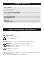
TABLE OF CONTENTS
CONTENTS
CHORE-TIME WARRANTY ......................................................................................................... 2
TABLE OF CONTENTS ................................................................................................................. 3
SAFETY AND GENERAL INFORMATION .................................................................................... 3
INTRODUCTION AND PART NUMBERS ..................................................................................... 4
MOUNTING ................................................................................................................................... 5
ELECTRICAL CONNECTION ........................................................................................................ 5
SETUP AND ADJUSTMENT ......................................................................................................... 6
SPECIFICATIONS ......................................................................................................................... 7
OPERATION .................................................................................................................................. 7
TROUBLESHOOTING ................................................................................................................... 7
Signal words are used in conjunction with the safety–alert symbol to identify the severity of the warning.
DANGER indicates an imminently hazardous situation which, if not avoided,
WILL result in death or serious injury.
WARNING indicates a potentially hazardous situation which, if not avoided,
COULD result in death or serious injury.
CAUTION indicates a hazardous situation which, if not avoided,
MAY result in minor or moderate injury.
CAUTION, WARNING AND DANGER DECALS have been placed on the equipment to warn of potentially
dangerous situations. Care should be taken to keep this information intact and easy to read at all times. Replace missing or
damaged safety decals immediately.
SAFETY–ALERT SYMBOL
FOLLOW SAFETY INSTRUCTIONS
Carefully read all safety messages in this manual and on your equipment safety signs. Follow recommended precautions
and safe operating practices.
Keep safety signs in good condition. Replace missing or damaged safety signs.
THIS IS A SAFETY–ALERT SYMBOL. When you see this symbol on your equipment, be alert to the
potential for personal injury. This equipment is designed to be installed and operated as safely as possible...
however, hazards do exist.
Understanding Signal Words
SAFETY AND GENERAL INFORMATION

4
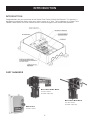
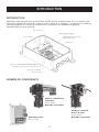
INTRODUCTION
INTRODUCTION
Congratulations on your purchase of the Chore-Time Poultry Winch Wall Control. This product is
designed to control the fastest and most robust winch of its kind. The installation of a Chore-Time
Feeder Cable Winch and Wall Control ensures extreme longevity and trouble free operation.
PART NUMBERS
Direct Drive Cable Winch
Part No. 56928.
Available separately.
Direct Drive Belt Winch
Part No. 56929.
Available separately.
Wall Control
Part No. 56930

5
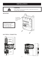
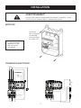
INSTALLATION
CAUTION
When drilling or punching conduit entries, take extreme care not to
damage internal components.
MOUNTING
ELECTRICAL CONNECTION
Use external
mounting holes
to retain IP55
rating
Suitable UL listed Liquid
Tight Cordgrips (glands)
must be used; cable
diameter 0.260” (Minimum)
to 0.545” (Maximum).
RESET
AMP
ADJUST
CLOSE LIMIT
OPEN LIMIT
L1 L2
F
R
L1
L2
E
NO
NC
NO
M
E

6
OF
1
1:10
1
VERSION
SHEET
NUMBER
SCALE
FINISH
MATERIAL
NAME
ALL DIMENSIONS IN mm UNO
A
E
C
G
H
F
D
B
H
G
F
E
D
C
B
109765432
A
1 8
81 2 3 4 5 6 7 9 10
I
I
THIRD ANGLE PROJECTION
CONFIDENTIAL
THIS DRAWING, ANY INFORMATION CONTAINED
HEREIN, AND ANY ASSOCIATED DATA AND
MATERIALS (COLLECTIVELY,"INFORMATION") IS
THE SOLE AND EXCLUSIVE PROPERTY OF, AND IS
PROPRIETARY TO, THE CHAMBERLAIN GROUP,
INC. THIS INFORMATION MAY NOT BE
REPRODUCED, COPIED, MODIFIED, DISCLOSED,
TRANSFERRED OR MADE AVAILABLE TO OTHERS,
IN WHOLE OR IN PART, WITHOUT THE PRIOR
EXPRESS WRITTEN CONSENT OF CHAMBERLAIN.
W1000C1-CT
NUMBER:
W1000C1-CT
1.1
1.1
STATE
Production
SIZE
A3
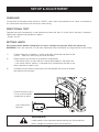
SETUP & ADJUSTMENT
OVERLOAD
On the back of the motor there will be an “AMPS” value, adjust the overload to this value. If uncertain of
this value leave over-load at the minimum value setting.
DIRECTIONAL TEST
Operate the winch momentarily in one direction to check that the UP switch will lift the load. If incorrect,
isolate mains power and proceed as follows:
- Swap F and R
SETTING LIMITS
Disconnect power before setting limits as mains voltages are present within the enclosure.
WARNING: Limits are sensitive; a small cam movement may correspond to a large amount winch travel.
1) Position one cam to depress a switch (the other should be well clear of the
switch). - Note the switch that you have activated
2) Supply power and activate in up direction momentarily
- If the winch hoists up then the limit switch noted above is the lower limit
- If the winch doesn't move it is the upper limit (momentarily activate in the
down direction to confirm this)
3) Proceed to adjust each friction held cam and operate the winch to achieve
the required set positions.
Friction held limit cams.
Use a small flat blade
screwdriver to adjust
Limit microswitch
terminals
WARNING!
Isolate power to the controller before opening the limit enclosure.
Mains voltages are present within the enclosure!
LIMIT MICROSWITCH TERMINALS

7
SPECIFICATIONS & OPERATION
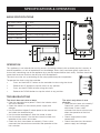
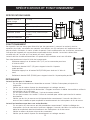
56930 SPECIFICATIONS
OPERATION
This appliance is not intended for use by persons (including children) with reduced physical, sensory or
mental capabilities, or lack of experience and knowledge, unless they have been given supervision or
instruc-tion concerning use of the appliance by a person responsible for their safety. Children should be
supervised to ensure that they do not play with the appliance.
The winch must be set up according to the setup procedure prior to operation..
To operate the winch using the controller
• Press and hold the UP button on the controller to raise using the winch
• Release the UP button to stop the winch at any position.
• Press and hold DOWN to lower using the winch.
• Release the DOWN button to stop the winch at any position.
Full Load Current 7.1 Amp
Voltage 230V
Phase Single Phase (2 x Hot Wire)
Frequency 60Hz
Suitable Operator 1.1kW (1.5Hp) Single Phase 5-Wire
Ingress Protection IP55
Application Indoor use only
10.24in
260mm
6.00in
152.5mm
4 -
0.24in
6mm
4.86in
123.5mm
9.45in
240mm
4.47in
113.5mm
5.51in
140mm
3 -
0.77in
19.5mm
10.24in
260mm
6.00in
152.5mm
4 -
0.24in
6mm
4.86in
123.5mm
9.45in
240mm
4.47in
113.5mm
5.51in
140mm
3 -
0.77in
19.5mm
STOP
UP
DOWN
The winch does not raise or lower
• Does the controller have power? Check the isolator switch
and circuit breaker.
• Check the motor has the correct power supply and
voltages.
• Has the overload tripped? Isolate power to the control box
and check the overload reset.
• Has the motor overheated? Allow the motor to cool.
• Has the motor seized? Use the hand crank to check the
operation of the winch and motor.
• Check the limits have been set correctly. Excess wires
crammed into the enclosure can affect the operation of the
limit switches.
The winch only drives in one
direction
• Have the limits been set correctly?
Check limit switch wiring and
adjustment. Excess wires
crammed into the en-closure can
affect the operation of the limit
switches.
• Check single phase motor
connections.
• Check the motor has the correct
power supply and voltages.
TROUBLESHOOTING

8
LIMITE DE GARANTIE
CTB, Inc. («Chore-Time») garantit que la nouvelle commande murale de treuil à volaille CHORE-TIME libre de
tout défaut dans ses matériaux ou fabrication dans le cadre d’une utilisation et de conditions normales, pendant
un (1) an à partir de la date d’installation par l’acheteur initial («Garantie»). Chore-Time fournit une extension de
la sus-mentionnée période de garantie («Extension de période de garantie») quant à certaines parties du
produit. Si l’existence d’un défaut est déterminée par Chore-Time au cours de la période applicable, Chore-
Time devra, à sa discrétion, (a) réparer gratuitement la pièce ou le produit, depuis ou par l’usine de fabrication
ou (b) remplacer gratuitement la pièce ou le produit, depuis ou par l’usine de fabrication. Cette garantie n’est
pas transmissible et ne s’applique qu’à l’acheteur initial du produit.
CONDITIONS ET LIMITES
CETTE GARANTIE REPRÉSENTE LA SEULE ET TOTALE GARANTIE DE CHORE-TIME, ET CHORE-TIME
DÉCLINE EXPRESSÉMENT TOUTE AUTRE GARANTIE, COMPRENANT SANS S’Y LIMITER LES GARANTIES
EXPRESSES ET IMPLICITES, COMPRENANT SANS S’Y LIMITER LES GARANTIES QUANT À LA
COMMERCIABILITÉ OU L’ADAPTATION À UN USAGE PARTICULIER.
CHORE-TIME ne peut être tenu responsable pour tout dommage direct, indirect, fortuit, subséquent ou
spécifique dont tout acheteur pourrait subir ou déclarer subir suite à un défaut de production. Les dommages
fortuits ou spéciaux cités dans la présente comprennent sans s’y limiter la perte ou les dommages sur des
produits ou biens, les coûts de transport, les pertes de vente, la perte de commandes, la perte de revenus, des
frais généraux plus élevés, des frais de travail ou fortuits et inefficacités opérationnelles. Certaines juridictions
interdisent les limites sur les garanties implicites et/ou l’exclusion ou limite de tels dommages, dès lors ces
limites et exclusions peuvent ne pas s’appliquer à vous. Cette garantie fournit à l’acheteur initial des droits
légaux spécifiques. Vous pouvez également disposer d’autres droits selon votre juridiction spécifique.
Le respect des règles fédérales, nationales et locales qui s’appliquent à l’emplacement, l’installation et
l’utilisation du produit échoient à l’acheteur initial, et CHORE-TIME ne peut être tenu responsable de tout
dommage qui résulterait d’un non-respect de ces règles.
• Les circonstances suivantes doivent entraîner l’invalidité de cette Garantie:
• Modifications apportées au produit qui ne sont pas spécifiquement déterminées par le manuel du produit.
• Le produit n’est pas installé et/ou utilisé dans le respect des instructions publiées par CHORE-TIME.
• Tous les composants du produit ne sont pas l’équipement d’origine fourni par CHORE-TIME.
• Le produit n’a pas été acheté auprès de et/ou installé par un distributeur CHORE-TIME autorisé ou certifié
ou un représentant.
• Le produit connaît un dysfonctionnement ou une panne suite à une mauvaise utilisation, un usage forcé, une
mauvaise gestion, une négligence,
une modification, un accident, un manque d’entretien correct ou résultant d’un coup de foudre, une
surcharge électrique ou
une coupure électrique.
• Le produit connaît une corrosion, une détérioration de matériel et/ou un mauvais fonctionnement de
l’équipement dû à ou
suite à l’application de produits chimiques, minéraux, sédiments ou tout autre élément étranger.
• Le produit a été utilisé pour tout autre but que celui destiné au soin des volailles et bétail.
La Garante et extension de Garantie ne peuvent être modifiées que par écrit par un représentant de CHORE-
TIME. CHORE-TIME n’endosse aucune obligation ou responsabilité de toute représentation ou garantie incarnée
par ou au nom de tout distributeur, revendeur, agent ou représentant certifié.
Entrée en vigueur: Avril 2014
GARANTIE CHORE-TIME

9
TABLE DES MATIÈRES
TABLE DES MATIÈRES
GARANTIE CHORE-TIME ............................................................................................................ 8
TABLE DES MATIÈRES ................................................................................................................ 9
INFORMATIONS GÉNÉRALES ET DE SÉCURITÉ ....................................................................... 9
INTRODUCTION ET NOMBRE E COMPOSANTS ..................................................................... 10
MONTAGE ................................................................................................................................... 11
CONNEXION ÉLECTRIQUE........................................................................................................ 11
INSTALLATION ET RÉGLAGE .................................................................................................... 12
SPÉCIFICATIONS ....................................................................................................................... 13
FONCTIONNEMENT ................................................................................................................... 13
DÉPANNAGE ............................................................................................................................... 13
Les mots de signalisation sont utilisés conjointement avec les symboles d’alerte de sécurité pour identifier la gravité de
l’avertissement.
DANGER indique une situation dangereuse immédiate qui, si elle n’est pas évitée, PROVOQUERA la mort ou
une blessure grave.
AVERTISSEMENT indique une situation potentiellement dangereuse qui, si elle n’est pas évitée, POURRAIT
provoquer la mort ou une blessure grave.
ATTENTION indique une situation dangereuse qui, si elle n’est pas évitée, POURRAIT provoquer une blessure
mineure ou moyenne.
DES ÉTIQUETTES DE PRÉCAUTION, AVERTISSEMENT ET DANGER ont été placées sur l’équipement
afin de prévenir des potentielles situations dangereuses. Une attention particulière doit être protée afin de conserver ces
informations intactes et lisibles à tout moment. Remplacer toute étiquette de sécurité manquante ou endommagée
immédiatement.
SYMBOLES DE SÉCURITÉ - D’ALERTE
SUIVRE LES CONSIGNES DE SÉCURITÉ
Lire attentivement tous les messages de sécurité de ce manuel et sur les signaux de sécurité de votre équipement. Suivre
les précautions recommandées et les pratiques d’utilisation sécurisées.
Conserver les signaux de sécurité en bon état. Remplacer toute étiquette de sécurité manquante ou endommagée.
CECI EST UN SYMBOLE D’ALERTE DE SÉCURITÉ Lorsque vous voyez ce symbole sur votre
équipement, un risque de blessure personnelle est présent. Cet équipement est conçu pour être installé et
utilisé de manière aussi sécurisée que possible... toutefois, le risque est inhérent.
Comprendre les mots de signalisation
INFORMATIONS GÉNÉRALES ET DE SÉCURITÉ

10
INTRODUCTION
INTRODUCTION
Félicitations pour votre achat de la commande murale de treuil à volaille Chore-Time. Ce produit a été
conçu pour contrôler le treuil le plus rapide et le plus solide de sa catégorie. L’installation d’un câble de
treuil de mangeoire et commande murale Chore-Time garantit une excellente longévité de
fonctionnement en toute quiétude.
NOMBRE DE COMPOSANTS
Câble de commande de
treuil direct
Partie n°56928
Disponible séparément.
Sangle de commande
directe de treuil
Partie n°56929
Disponible séparément.
Commande murale
Partie n°56930
Haut contacteur
Bouton de réglage de surcharge (à régler lors de
l'installation en fonction du courant du moteur)
Test de recouvrement
(bouton rouge)
Bas contacteur
Verrouillage mécanique
Réinitialisation de surcharge
(bouton bleu foncé)
Surcharge

11
INSTALLATION
AVERTISSEMENT
Lorsque vous percez ou poinçonnez les entrées de conduits, soyez
attentif à ne pas endommager les composants internes.
MONTAGE
CONNEXION ÉLECTRIQUE
Utilisez les
trous extérieurs
de montage
pour conserver
les côtes IP55
RESET
AMP
ADJUST
CLOSE LIMIT
OPEN LIMIT
L1 L2
F
R
L1
L2
E
NO
NC
NO
M
E
limite de fermeture
limite
ouverte
Régler
l'ampli
Réinitialiser
Bas
Un presse-étoupe
approuvé UL doit
être utilisé avec
l'installation

12
OF
1
1:10
1
VERSION
SHEET
NUMBER
SCALE
FINISH
MATERIAL
NAME
ALL DIMENSIONS IN mm UNO
A
E
C
G
H
F
D
B
H
G
F
E
D
C
B
109765432
A
1 8
81 2 3 4 5 6 7 9 10
I
I
THIRD ANGLE PROJECTION
CONFIDENTIAL
THIS DRAWING, ANY INFORMATION CONTAINED
HEREIN, AND ANY ASSOCIATED DATA AND
MATERIALS (COLLECTIVELY,"INFORMATION") IS
THE SOLE AND EXCLUSIVE PROPERTY OF, AND IS
PROPRIETARY TO, THE CHAMBERLAIN GROUP,
INC. THIS INFORMATION MAY NOT BE
REPRODUCED, COPIED, MODIFIED, DISCLOSED,
TRANSFERRED OR MADE AVAILABLE TO OTHERS,
IN WHOLE OR IN PART, WITHOUT THE PRIOR
EXPRESS WRITTEN CONSENT OF CHAMBERLAIN.
W1000C1-CT
NUMBER:
W1000C1-CT
1.1
1.1
STATE
Production
SIZE
A3
INSTALLATION ET RÉGLAGE
SURCHARGE
À l’arrière du moteur se trouve une valeur «AMPS», ajustez la charge à cette valeur. Si vous n’êtes pas
certain de ce que cette valeur soulève, chargez à la valeur minimum.
TEST DE DIRECTION
Faites fonctionner le treuil momentanément dans une direction pour vérifier que l’interrupteur HAUT
soulèvera la charge. Si cela ne fonctionne pas, séparez l’alimentation générale et procédez de la manière
suivante:
- Inversez F et R
LIMITES D’INSTALLATION
Débranchez le courant avant d’établir les limites, car des niveaux de tensions dangereux sont
présents.
AVERTISSEMENT: Les limites sont sensibles; un petit mouvement des cames peut correspondre à
une grande distance de levage pour le treuil.
1) Positionnez une came pour abaisser un interrupteur (l’autre doit être éloigné de
l’interrupteur). - Notez lequel des interrupteurs vous avez activé
2) Branchez l’alimentation et activez la position de levage vers le haut momentanément
Si le treuil lève la charge, alors l’interrupteur de limite noté ci-dessus est la limite inférieure
Si le treuil ne bouge pas, vous avez atteint la limite supérieure (activez momentanément
vers le bas pour le confirmer)
3) Procédez de manière à ajuster chaque friction des cames et enclenchez le treuil pour atteindre
les positions paramétrées désirées.
Limites de friction des
cames. Utilisez un petit
tourne-vis plat pour les
ajuster
Terminaux de limite
de microcontact
AVERTISSEMENT!
Stoppez le courant de la commande avant d’ouvrir le boîtier des interrupteurs
de fin de course. Un voltage élevé est présent dans le boîtier!
LIMIT MICROSWITCH TERMINALS

13
SPÉCIFICATIONS ET FONCTIONNEMENT
SPÉCIFICATIONS 56930
FONCTIONNEMENT
Ce dispositif n’est pas conçu pour être utilisé par des personnes (y compris les enfants) dont les
capacités physiques, sensorielles ou mentales sont réduites, ou qui manquent de l’expérience et des
connaissances suffisantes, à moins qu’elles disposent d’une surveillance ou des instructions concernant
l’utilisation de l’appareil par une personne responsable de leur sécurité. Les enfants doivent être
surveillés afin de s’assurer qu’ils ne jouent pas avec l’appareil.
Le treuil doit être installé conformément à la procédure d’installation avant son utilisation.
Pour faire fonctionner le treuil à l’aide de la commande
• Maintenez appuyé sur le bouton HAUT (UP) sur la commande pour lever
à l’aide du treuil
• Relâchez le bouton HAUT (UP) pour stopper le treuil à n’importe
quelle position.
• Maintenez appuyé sur le bouton BAS (DOWN) pour abaisser à l’aide du
treuil.
• Relâchez le bouton BAS (DOWN) pour stopper le treuil à n’importequelle position.
Courant nominal à
pleine charge
7,1 Amp
Voltage 230V
Phase Phase unique (2 x câble chaud)
Fréquence 60Hz
Opérateur qualifié 1.1kW (1.5Hp) Phase Unique
5-Câble
Indice de Protection IP55
Usage Utilisation en intérieur uniquement
10.24in
260mm
6.00in
152.5mm
4 -
0.24in
6mm
4.86in
123.5mm
9.45in
240mm
4.47in
113.5mm
5.51in
140mm
3 -
0.77in
19.5mm
10.24in
260mm
6.00in
152.5mm
4 -
0.24in
6mm
4.86in
123.5mm
9.45in
240mm
4.47in
113.5mm
5.51in
140mm
3 -
0.77in
19.5mm
STOP
HAUT
BAS
Le treuil ne lève pas ni n’abaisse
• Est-ce que la commande est branchée au courant? Vérifiez l’interrupteur principal et le
disjoncteur.
• Vérifiez que le moteur dispose des branchements et voltages corrects.
• Est-ce que la surcharge a été déclenchée? Stoppez le courant du boîtier de contrôle et vérifiez la
réinitialisation de la surcharge.
• Est-ce que le moteur a surchauffé? Laissez le moteur refroidir.
• Est-ce que le moteur s’est arrêté? Utilisez la manivelle pour vérifier que le treuil et le moteur
fonctionnent
• Vérifiez que les fins de courses ont été paramétrées correctement. Un excès de câble s’est
entassé dans le boîtier et peut empêcher le fonctionnement des interrupteurs de fin de course.
Le treuil ne fonctionne que dans une seule direction
• Est-ce que les fins de courses ont été paramétrées correctement? Vérifiez le câblage des
interrupteurs de fin de course ainsi que leurs réglages. Un excès de câble s’est entassé dans le
boîtier et empêche le bon fonctionnement des interrupteurs de fin de course.
• Vérifiez le moteur de phase unique et les connexions.
• Vérifiez que le moteur dispose des branchements et voltages corrects.
DÉPANNAGE

14
NOTES

15
NOTES

POULTRY WINCH WALL CONTROL
INSTRUCTION MANUAL - P2
COMMANDE MURALE DE TREUIL À VOLAILLE
MANUEL D’UTILISATION - P8
CG Ref: D-M-ACG/080
For additional parts and information, contact your nearest Chore-Time
distributor or representative.
Find your nearest distributor at: www.choretime.com/contacts
CTB, Inc.
PO Box 2000
Milford, Indiana 46542-2000 USA
Phone (574) 658-4101 Fax (877) 730-8825
Email: [email protected]
Internet: www.choretime.com
MADE TO WORK.
BUILT TO LAST.®
Revisions to this Manual
Page No. Description of Change ECO
-
 1
1
-
 2
2
-
 3
3
-
 4
4
-
 5
5
-
 6
6
-
 7
7
-
 8
8
-
 9
9
-
 10
10
-
 11
11
-
 12
12
-
 13
13
-
 14
14
-
 15
15
-
 16
16


Chore-Time MF2500A Poultry Winch Wall Control Mode d'emploi
- Taper
- Mode d'emploi
Documents connexes


Autres documents
-
Maytag MHW3000BG1 Le manuel du propriétaire
-
Maytag MHW8000AW0 Manuel utilisateur
-
Maytag MHW4100DW0 Le manuel du propriétaire
-
Maytag MHW7000AW2 Le manuel du propriétaire
-
-
 STAHL CraneSystems Winch Le manuel du propriétaire
-
Kenmore 22-42729701 Manuel utilisateur
-
