
Please read the operating instructions carefully before using this product, and keep the operating
instructions for future use.
See page 32 for all model numbers.
Operating Instructions
Pharmaceutical Refrigerator
MPR-S163


1
CONTENTS
INTRODUCTION P. 2
PRECAUTIONS FOR SAFE OPERATION P. 3
SYMBOLS ON THE UNIT P. 6
ENVIRONMENTAL CONDITIONS P. 7
REFRIGERATOR COMPONENTS P. 8
Control panel components P. 10
INSTALLATION SITE P. 11
INSTALLATION P. 12
Installation of shelf P. 12
START-UP OF UNIT P. 13
CHAMBER TEMPERATURE SETTING P. 14
KEY LOCK FUNCTION P. 15
DEFROSTING P. 15
LED LIGHTING TIME SETTING P. 16
ALARM TEMPERATURE SETTING P. 17
Setting of high temperature alarm P. 17
Setting of low temperature alarm P. 18
SETTING OF DELAY OF DOOR ALARM P. 19
SETTING OF ALARM BUZZER RECOVERY P. 20
OPERATION CHECK AFTER RECOVERY P. 21
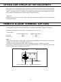
REMOTE ALARM TERMINAL (OPTION) P. 21
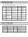
ALARM FUNCTIONS P. 22
SAFETY FUNCTIONS P. 22
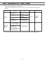
SELF DIAGNOSTIC FUNCTIONS P. 23
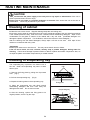
ROUTINE MAINTENANCE P. 24
Cleaning of cabinet P. 24
Cleaning of evaporating tray P. 24
TROUBLESHOOTING P. 25
DISPOSAL OF UNIT P. 25
Decontamination of chamber P. 25
TEMPERATURE RECORDER (OPTION) P. 30
INTERFACE BOARD (OPTION) P. 30
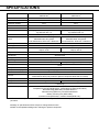
SPECIFICATIONS P. 31
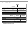
PERFORMANCE P. 32
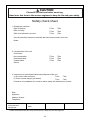
SAFETY CHECK SHEET P. 33

2
INTRODUCTION
■ Read the operating instructions carefully before using the appliance and follow the instructions for
safety operation.
■ PHC Corporation never guarantees any safety if the appliance is used for any objects other than intended
use or used by any procedures other than those mentioned in the operating instructions.
■ Keep the operating instructions in an adequate place to refer to it as necessary.
■ The contents of the operating instructions will be subjected to change without notice due to the
improvement of performance or functions.
■ Contact our sales representative or agent if any page of the operating instructions is lost or page order
is incorrect.
■ Contact our sales representative or agent if any point in the operating instructions is unclear or if there
are any inaccuracies.
■ No part of the operating instructions may be reproduced in any form without the expressed written
permission of PHC Corporation.
IMPORTANT NOTICE
PHC Corporation guarantees this product under certain warranty conditions. However, please note that
PHC Corporation shall not be responsible for any loss or damage to the contents of the product.
<Intended Use>
This equipment is designed for storage of pharmaceuticals, samples and reagents.

3
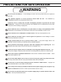
PRECAUTIONS FOR SAFE OPERATION
It is imperative that the user complies with the operating instructions
as it contains important safety advice.
Items and procedures are described so that you can use this unit correctly and safely.
If the precautions advised are followed, this will prevent possible injury to the user and
any other person.
Precautions are illustrated in the following way:
WARNING
Failure to observe WARNING signs could result in a hazard to personnel
possibly resulting in serious injury or death.
CAUTION
Failure to observe CAUTION signs could result in injury to personnel and
damage to the unit and associated property.
Symbol shows;
This symbol means caution.
This symbol means an action is prohibited.
This symbol means an instruction must be followed.
Be sure to keep the operating instructions in a place accessible to users of this unit.

4
PRECAUTIONS FOR SAFE OPERATION
Do not use the unit outdoors. Current leakage or electric shock may result if the unit is exposed to
rain water.
Only qualified engineers or service personnel should install the unit. The installation by
unqualified personnel may cause electric shock or fire.
Install the unit on a sturdy floor and take an adequate precaution to prevent the unit from
turning over. If the floor is not strong enough or the installation site is not adequate, this may result
in injury from the unit falling or tipping over.
Never install the unit in a humid place or a place where it is likely to be splashed by water.
Deterioration of the insulation may result which could cause current leakage or electric shock.
Never install the unit in a flammable or volatile location. This may cause explosion or fire.
Never install the unit where acid or corrosive gases are present as current leakage or electric
shock may result due to corrosion.
Always ground (earth) the unit to prevent electric shock. If the power supply outlet is not
grounded, it will be necessary to install a ground by qualified engineers.
Never ground the unit through a gas pipe, water main, telephone line or lightning rod. Such
grounding may cause electric shock in the case of an incomplete circuit.
Connect the unit to a power source as indicated on the rating label attached to the unit. Use
of any other voltage or frequency other than that on the rating label may cause fire or electric shock.
Never store volatile or flammable substances in this unit if the container cannot be sealed. These
may cause explosion or fire.
Do not insert metal objects such as a pin or a wire into any vent, gap or any outlet on the unit.
This may cause electric shock or injury by accidental contact with moving parts.
Use this unit in safe area when treating the poison, harmful or radiate articles. Improper use
may cause bad effect on your health or environment.
Turn off the power switch (if provided) and disconnect the power supply to the unit prior to any
repair or maintenance of the unit in order to prevent electric shock or injury.
Do not touch any electrical parts (such as power supply plug) or operate switches with a wet
hand. This may cause electric shock.
WARNING

5
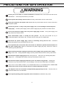
PRECAUTIONS FOR SAFE OPERATION
Ensure you do not inhale or consume medication or aerosols from around the unit at the time of
maintenance. These may be harmful to your health.
Never splash water directly onto the unit as this may cause electric shock or short circuit.
Never put containers with liquid on the unit as this may cause electric shock or short circuit when
the liquid is spilled.
Never bind, process, or step on the power supply cord, or never damage or break the power
supply plug. A broken power supply cord or power supply plug may cause fire or electric shock.
Do not use the power supply cord if its power supply plug is loose. Such power supply cord
may cause fire or electric shock.
Never disassemble, repair, or modify the unit yourself. Any such work carried out by an
unauthorized person may result in fire, or electric shock or injury due to a malfunction.
Disconnect the power supply plug if there is something wrong with the unit. Continued
abnormal operation may cause electric shock or fire.
Do not position this unit and the other unit so that it is difficult to operate the disconnection of
the power supply plug. Failure to disconnect the power supply plug may cause fire if there is
something wrong with the unit.
When removing the power supply plug from the power supply outlet, grip the power supply
plug, not the cord. Pulling the power supply cord may result in electric shock or fire by short circuit.
Disconnect the power supply plug before moving the unit. Take care not to damage the power
supply cord. A damaged power supply cord may cause electric shock or fire.
Disconnect the power supply plug when the unit is not used for long periods. Keeping the
connection may cause electric shock, current leakage, or fire due to the deterioration of insulation.
If the unit is to be stored unused in an unsupervised area for an extended period, ensure that
children do not have access and that doors are locked completely with a key.
The disposal of the unit should be accomplished by appropriate personnel. Remove doors to
prevent accidents such as suffocation.
Do not put the packing plastic bag within reach of children as suffocation may result.
WARNING

6
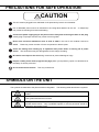
PRECAUTIONS FOR SAFE OPERATION
This unit must be plugged into a dedicated circuit protected by branch circuit breaker.
Use a dedicated power source as indicated on the rating label attached to the unit. A multiple-tap
may cause fire resulting from abnormal heating.
Connect the power supply plug to the power source firmly after removing the dust on the plug.
A dusty plug or improper insertion may cause a heat or ignition.
Never store corrosive substances such as acid or alkali in this unit if the container cannot be
sealed. These may cause corrosion of inner components or electric parts.
Check the setting when starting up of operation after power failure or turning off of power
switch. The stored items may be damaged due to the change of setting.
Be careful not to tip over the unit during movement to prevent damage or injury.
Prepare a safety check sheet (copy the last page) when you request any repair or maintenance for
the safety of service personnel.
Do not touch the hot surface. This may cause burns.
SYMBOLS ON THE UNIT
The symbols are attached to the pharmaceutical refrigerator. The following table describes the symbols.
This symbol indicates that caution is required. Refer to product documentation for
details.
This symbol indicates a hot surface.
This symbol is attached to covers that access high-voltage electrical components to
prevent electric shock. Only a qualified engineer or service personnel should be
allowed to open these covers.
CAUTION

7
ENVIRONMENTAL CONDITIONS
This equipment is designed to be safe at least under the following conditions (based on the IEC 61010-1):
■ Indoor use;
■ Altitude up to 2000 m;
■ Temperature 5 oC to 40 oC;
■ Maximum relative humidity 80 % for temperature up to 31 oC decreasing linearly to 50 % relative
humidity at 40 oC;
■ Mains supply voltage fluctuations up to ±10 % of the nominal voltage;
■ Transient overvoltages up to the levels of OVERVOLTAGE CATEGORY II;
■ Temporary OVERVOLTAGES occurring on the mains supply;
■ Applicable pollution degree of the intended environment (POLLUTION DEGREE 2 in most cases);

8
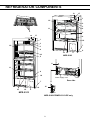
Rear side
REFRIGERATOR COMPONENTS
2
17
19
18
13
1
MPR-S163
10 8
3
2
6
4
9
11
12
5
7
18
19
17
MPR-S313
1
3
2
4
6
5
7
10
11
12
1
3
8
9
16
MPR-S163-PE/MPR-S313-PE only
15
14
6
Power supply cord

9
REFRIGERATOR COMPONENTS
1. Door switch
2. LED light: White LED light.
3. Air intake vent: Be careful not to block off. If air intake vent is blocked, the chamber temperature
becomes unstable. Also be careful not to insert the finger or enter the foreign materials.
4. Air circulating fan: Circulate the cooled air in the chamber.
5. Air exhaust vent: Be careful not to block off.
6. Access port: This port allows cables to be passed into the chamber.
Note: If an instrument requiring a power source is placed inside the chamber, the cable can be led
through the access port. After installation, a rubber cap should be used to seal the access port. Failure
to do this can affect the temperature uniformity inside the chamber and lead to condensation on the
outside of the access port.
7. Caster: Mounted on the back side. When moving the unit, tilt the unit backward a little for easy
carrying.
8. Leveling foot: Adjust the height by screw bolt to install the unit in level.
9. Space for a temperature recorder: Location for an optional temperature recorder. (page 30)
10. Key lock: Insert the key and turn to the clockwise 180o with pressing into the head of lock when lock
the doors.
11. Shelf
12. Door: Consists of double pair glass with heat ray reflection film. Be careful not to break the glass.
13. Control panel: Displays operating condition of the unit and used to set chamber temperature etc.
(page 10)
14. Evaporating tray: Places in rear bottom of the frame. Pull out forward for removing. (page 24)
15. Power switch (MPR-S163-PE and MPR-S313-PE only): This is for turning ON/OFF the power to the
unit. (ON-“l”, OFF-“○”)
16. Exhaust vent cover (MPR-S313 only): Always install the exhaust vent cover on the back of the shelf
when the shelf is located at the front of the air exhaust vent.
17. Space for battery mounting box: A battery mounting box can be attached here. Switch on the
battery switch of the battery mounting box. (page 21)
18. Drain board: The samples can be placed on a drain board.
19. Drain cap: Remove the cap when the water resulting from defrosting is drained. The drained water is
evaporated in the evaporating tray under the unit. Attach the cap after drainage.

10
REFRIGERATOR COMPONENTS
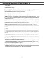
Control panel components
1. Door check indicator (DOOR): The red LED lamp is lit when the door is opened.
(After 2 minutes the door check indicator lights; the alarm buzzer is activated to notice the door opening.)
2. Alarm indicator (ALARM): The red LED lamp blinks during an alarm status. (page 22, 23)
3. Temperature display: Normally, the current chamber temperature is displayed in the temperature
display. When the high/low temperature alarm or 0 o
C alarm is activated, the current chamber
temperature blinks (refer to page 22). When the self-diagnostic function detects an abnormality, the
error cord is displayed (refer to page 23).
4. Numerical value shift key ( ): Pressing this key for 5 seconds at temperature display mode causes
the setting mode. Pressing this key at setting mode makes the figure on the temperature display to
change.
5. Digit shift key ( ): Pressing this key at setting mode makes the digit to be inputted on the
temperature display to change. Pressing this key for 5 seconds at temperature display mode causes the
setting mode for key lock.
6. Set key (SET): Pressing this key at temperature display mode enables the temperature setting.
( page 14) Pressing this is at the end of setting mode memorizes the setting.
7. Alarm buzzer stop key (BUZZER): Pressing this key silences the alarm buzzer when the alarm
buzzer sounds. But the remote alarm is not canceled.
8. LED light key (LIGHT): Turn on the LED light by pressing this key. To turn off the LED light, press
this key again. If it is turned on by LED light key, it will be turned off automatically after setting time.
LED light turns off when the door is opened and then closed.
■“temperature display mode”: the status which the temperature display shows the current chamber
temperature
■“setting mode”; the status which the temperature display is ready to be entered after pressing
numerical value shift key for about 5 seconds.
8 7 6 5
2
1 3
4

11
INSTALLATION SITE
To operate this unit properly and to obtain maximum performance, install the unit in a location with the
following conditions:
■ A location not subjected to direct sunlight
Do not install the unit under direct sunlight. Installation in a location subjected to direct sunlight cannot
obtain the intended performance.
■ A location with adequate ventilation
Leave at least 10 cm around the unit for ventilation. Poor ventilation will result in a reduction of the
performance and consequently the failure.
■ A location away from heat generating sources
Avoid installing the unit near heat-emitting appliances such as a heater or a boiler etc. Heat can
decrease the intended performance of the unit.
■ A location with little temperature change
Install the unit under stable ambient temperature. The allowable ambient temperature is between -5 oC
and 35 oC.
■ A location with a sturdy and level floor
Always install the unit on a sturdy and level floor. The uneven floor or tilted installation may cause failure
or injury. Install the unit in stable condition to avoid the vibration or noise. Unstable condition may
cause vibration or noise.
WARNING
Install the unit on a sturdy floor. If the floor is not strong enough or the installation site is not
adequate, this may result in injury from the unit falling or tipping over.
Select a level and sturdy floor for installation. This precaution will prevent the unit from tipping.
Improper installation may result in water spillage or injury from the unit tipping over.
■ A location not prone to high humidity
Install the unit in the ambient of 80 %R.H. or less humidity. Installation under high humidity may cause
current leakage or electric shock.
WARNING
Do not use the unit outdoors. Current leakage or electric shock may result if the unit is exposed to
rain water.
Never install the unit in a humid place or a place where it is likely to be splashed by water.
Deterioration of the insulation may result which could cause current leakage or electric shock.
■ A location without flammable or corrosive gas
Never install the unit in a location where it will be exposed to flammable or corrosive gas. This may
cause explosion or fire or may result in the current leakage or electric shock by the corrosion of the
electrical components.
■ A location without the possibility of anything fall
Avoid installing the unit in the location where anything can fall down onto the unit. This may cause the
breakdown or failure of the unit.

12
INSTALLATION
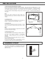
1. Removing the packing materials and tapes
Remove all transportation packaging materials and tapes. Open the doors and ventilate the unit. If the
outside panels are dirty, clean them with a diluted neutral dishwashing detergent. (Undiluted detergent
can damage the plastic components. For the dilution, refer to the instruction of the detergent.) After
the cleaning with the diluted detergent, always wipe it off with a wet cloth. Then wipe off the panels with
a dry cloth.
Note:
Remove the cable tie banding the power supply cord.
Prolonged banding may cause the corrosion of the cord
coating.
2. Installing the unit
Stretch the leveling feet by rotating them to contact them to
the floor. Ensure the unit is horizontally. (Fig. 1)
3. Fixing the unit
Two fixtures are attached to the rear of the frame. Fix the
frame to the wall with these fixtures and rope or chain.
(Fig. 2)
Note:
Contact our sales representative or agent if the unit should
be fixed for earthquake resistant.
4. Ground (earth) the unit
The ground (earth) is for preventing the electric shock in
the case of the electrical insulation is unanticipated
degraded. Always ground the unit at the time of
installation.
■ A 3-prong plug with grounding pole, there is no need for
electric work for grounding.
■ If the power supply outlet is not grounded, it will be
necessary to install a ground by qualified engineers.
Installation of shelf
The position of shelf stopper is changeable. Set the shelf
stopper at desired position. The shelf should be horizontal.
(MPR-S313 only)
Fig. 2
Fixture (back side)
Fig. 1
Leveling foot
Shrink
Stretch

13
START-UP OF UNIT
To commence the operation (initially or after temporary power off due to the cleaning, maintenance, etc.),
follow the procedure below:
■ The operation is resumed automatically after recovery from power failure with the setting before power
failure.
1. Check the power switch is OFF. (MPR-S163-PE and MPR-S313-PE only)
2. Check that the battery switch of battery mounting box for power failure alarm (optional component) is
OFF if the battery mounting box for power failure alarm is installed.
3. Connect the power supply cord to the dedicated power source before putting samples in the chamber.
4. Turn on the power switch. (MPR-S163-PE and MPR-S313-PE only)
At the power on, the high temp. alarm is activated. The alarm indicator blinks and the blinking chamber
temperature is displayed.
■ At the start-up with the factory setting, the high temp. alarm is activated when the chamber temperature
is higher than 10 oC, therefore the high temp. alarm works (High temp. alarm; temperature display blinks,
alarm indicator blinks, buzzer sounds after 15 minutes)
5. Set the desired chamber temperature. (page 14)
■ The factory setting of chamber temperature is 5 oC.
<Important>
■When the power supply has been turn off, wait 5 minutes or more after recovery of power supply,
connect the power supply plug to the outlet (and turn on the power switch of the MPR-S163-PE or
MPR-S313-PE). The compressor requires 5 minutes to re-start.
It takes about 1 hours to reach the set temperature (ambient temp. 30 oC, no load, without containers)
6. On the temperature display, check that the chamber temperature reaches the set temperature.
7. Turn on the battery switch of battery mounting box for power failure alarm (optional
component) if the battery mounting kit for power failure alarm is installed.
8. By opening the door, check that the LED light is on.
9. Put the samples in the chamber gradually.
■ Putting a large amount of samples in the chamber at a time causes the temperature rise.
■ Never block the air intake vent or air exhaust vent in the chamber.
10. As needed, set the alarm temperature (page 17 to 18), LED lighting time (page 16), delay of door
alarm (page 19), alarm buzzer recovery (page 20), and the lock of chamber temperature setting
(page 15).
<Attention>
■ The condensation may be found on the glass of refrigerator door under high temperature and
humidity condition. Wipe off the condensation with a soft dry cloth.

14
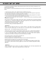
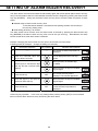
CHAMBER TEMPERATURE SETTING
Set the temperature of chamber according to the usage condition. This unit keeps the storage items for
long period with adequate chamber temperature.
Temperature
Setting range between 2 oC and 14 oC
Initial setting (at factory) 5 oC
The chamber temperature of 2 oC may cause partial freeze of stored items.
Example: Change the chamber temperature to 4 oC from 5 oC.
Following shows an example. Change the setting as necessary.
Description Operation Key operated Indication after operation
1
Connect the power supply cord to
the outlet.
(only when start-up of unit) -----
The current chamber temperature is
displayed.
Turn on the power switch.
(MPR-S163-PE/MPR-S313-PE
only)
2 Press the set key. SET The current setting is displayed and
the first digit blinks.
3
Set the temperature to 4 with the
digit shift key and the numerical
value shift key.
When pressed, the settable digit is
shifted.
When pressed, the figure of settable
digit changes.
4 Press the set key. SET
Set temperature is memorized and
the current chamber temperature is
displayed.
■ The setting mode returns to the temperature display mode automatically when 90 seconds has passed
without any key operation. In this case, any setting before pressing set key (SET) is not memorized.
<Important>
■ It is recommended to install a temperature recorder (optional component) to check the highest/lowest
chamber temperature when the item which needs severe temperature control is stored.

15
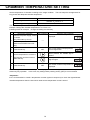
KEY LOCK FUNCTION
The temperature setting of chamber can be locked to avoid accidental change. When the lock is ON,
the change of chamber temperature is unable even if the key on the control panel is operated.
Initial setting (at factory): Lock is OFF
Display Mode Function
L 0 Lock is OFF Enable to change of temperature setting
L 1 Lock is ON Disable to change of temperature setting
Example: Changing the lock status to ON from OFF (initial setting).
Description Operation Key operated Indication after operation
1 ----- -----
The current chamber temperature
is displayed.
2 Press the digit shift key for about 5
seconds. The current setting is displayed and
the first digit blinks.
3 Press the numerical value shift
key and scroll the figure to 1 When pressed, the figure of settable
digit changes.
4 Press the set key SET
The key lock is set to ON.
The current chamber temperature
is displayed.
■ The setting mode returns to the temperature display mode automatically when 90 seconds has passed
without any key operation. In this case, any setting before pressing set key (SET) is not memorized.
DEFROSTING
The following 2 types of defrosting methods is provided for the refrigerator. Both of them are controlled
automatically.
● Cycle defrosting
The chamber temperature is kept stable by ON/OFF operation of the compressor. When the
compressor is OFF (stopped), the frost on the evaporator is melted by the heater. This defrosting never
influences to the chamber temperature.
● Defrosting by defrost sensor
The cycle defrosting may not be sufficient to remove the frost on the evaporator when the ambient
temperature is high, the door is opened frequently, or heavy moist items are stored in the chamber. In
this case, the defrosting operation is started automatically when the defrost sensor detects the frost.
During the defrosting, the current chamber temperature and dF is displayed alternately on the
temperature display.
After completion of defrosting, dF display is disappeared and normal operation resumes.
<Important>
■ During the defrosting, the chamber temperature reaches around 10 oC temporary.
■ Too much frost is accumulated on the evaporator when the chamber is running under high temperature
and humidity condition. For example, the unit starts to defrost once a week with 2 oC setting in the
ambient of 30 oC and 80%R.H.

16
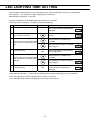
LED LIGHTING TIME SETTING
The LED light is automatically turned off after setting time when the LED light is turned on by pressing the
LED Light key. The method of change of lighting time is as follows.
Initial setting (at factory): 10 minutes
Example: Changing the LED lighting time to 5 minutes from 10 minutes
Following shows an example. Change the setting as necessary.
Description Operation Key operated Indication after operation
1 ----- -----
The current chamber temperature is
displayed.
2 Press the numerical value shift
key for about 5 seconds. F00 is displayed and the first digit
blinks.
3
Set the figure to F45 with the digit
shift key and numerical value shift
key.
When pressed, the settable digit
is shifted.
When pressed, the figure of settable
digit changes.
4 Press the set key. SET The current setting is displayed and
the first digit blinks.
5
Set the figure to 005 with the digit
shift key and the numerical value
shift key.
When pressed, the settable digit
is shifted.
When pressed, the figure of settable
digit changes.
6 Press the set key. SET
The setting is memorized and the
current chamber temperature is
displayed.
■ The setting mode returns to the temperature display mode automatically when 90 seconds has passed
without any key operation. In this case, any setting before pressing set key (SET) is not memorized.
■ The LED lighting time can be changed from 0 minute to 15 minutes.
■ The LED light keeps off when the lighting time set to 000 in procedure 5.

17
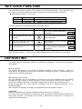
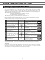
ALARM TEMPERATURE SETTING
Setting of high temperature alarm
The abnormal temperature rise is notified by the blink of alarm indicator and display of chamber
temperature, and the alarm buzzer (15 minutes after blink) when the high temperature alarm is set.
Always set the high temperature alarm to avoid the damage of storage items due to the temperature rise.
Settable range of high temperature alarm:
Between the set temperature of chamber plus 2 oC and
the set temperature of chamber plus 14 oC
Initial setting (at factory): the set temperature of chamber plus 5 oC
Example: Changing the high temperature alarm to 3 oC from 5 oC plus the set temperature of chamber.
Following shows an example. Change the setting as necessary.
Description Operation Key operated Indication after operation
1 ----- -----
The current chamber temperature
is displayed.
2 Press the numerical value shift
key for about 5 seconds. F00 is displayed and the first digit
blinks.
3 Press the numerical value shift
key and scroll the figure to 1. When pressed, the figure of settable
digit changes.
4 Press the set key. SET The current setting is displayed and
the first digit blinks.
5
Scroll the figure to 003 by using
the digit shift key and the
numerical value shift key.
When pressed, the settable digit
is shifted.
When pressed, the figure of settable
digit changes.
6 Press the set key. SET
Alarm temperature is memorized
and the current chamber
temperature is displayed.
■ The setting mode returns to the temperature display mode automatically when 90 seconds has passed
without any key operation. In this case, any setting before pressing set key (SET) is not memorized.
<Important>
■ The alarm may be activated after defrosting or when too much items are stored in the chamber,
depending on the setting of high temperature alarm. This is not a malfunction. The alarm is cancelled
automatically when the chamber temperature reaches the set temperature.

18
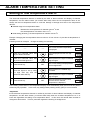
ALARM TEMPERATURE SETTING
Setting of low temperature alarm
The abnormal temperature descent is notified by the blink of alarm indicator and display of chamber
temperature, and the alarm buzzer (15 minutes after blink) when the low temperature alarm is set.
Always set the low temperature alarm to avoid the damage of storage items due to the temperature
descent.
Settable range of low temperature alarm:
Between the set temperature of chamber minus 2 oC and
the set temperature of chamber minus 14 oC
Initial setting (at factory): the set temperature of chamber minus 5oC
Example: Changing the low temperature alarm to minus 3 oC from minus 5 oC plus the set temperature of
chamber.
Following shows an example. Change the setting as necessary.
Description Operation Key operated Indication after operation
1 ----- -----
The current chamber temperature
is displayed.
2 Press the numerical value shift
key for about 5 seconds. F00 is displayed and the first digit
blinks.
3 Press the numerical value shift
key and scroll the figure to 2. When pressed, the figure of settable
digit changes.
4 Press the set key. SET The current setting is displayed and
the first digit blinks.
5
Scroll the figure to -03 by using
the digit shift key and the
numerical value shift key.
When pressed, the settable digit
is shifted.
When pressed, the figure of settable
digit changes.
6 Press the set key. SET
Alarm temperature is memorized
and the current chamber
temperature is displayed.
■ The setting mode returns to the temperature display mode automatically when 90 seconds has passed
without any key operation. In this case, any setting before pressing set key (SET) is not memorized.
<Important>
■ The abnormal temperature descent is notified by the blink of alarm indicator and display of chamber
temperature, and the alarm buzzer (15 minutes after blink) when the chamber temperature is 0 oC or
lower with regardless the setting of low temperature alarm. In this case, the remote alarm terminal is
changed to alarm status. This is a precaution against the freezing of storage items.
La page est en cours de chargement...
La page est en cours de chargement...
La page est en cours de chargement...
La page est en cours de chargement...
La page est en cours de chargement...
La page est en cours de chargement...
La page est en cours de chargement...
La page est en cours de chargement...
La page est en cours de chargement...
La page est en cours de chargement...
La page est en cours de chargement...
La page est en cours de chargement...
La page est en cours de chargement...
La page est en cours de chargement...
La page est en cours de chargement...
La page est en cours de chargement...
-
 1
1
-
 2
2
-
 3
3
-
 4
4
-
 5
5
-
 6
6
-
 7
7
-
 8
8
-
 9
9
-
 10
10
-
 11
11
-
 12
12
-
 13
13
-
 14
14
-
 15
15
-
 16
16
-
 17
17
-
 18
18
-
 19
19
-
 20
20
-
 21
21
-
 22
22
-
 23
23
-
 24
24
-
 25
25
-
 26
26
-
 27
27
-
 28
28
-
 29
29
-
 30
30
-
 31
31
-
 32
32
-
 33
33
-
 34
34
-
 35
35
-
 36
36


