RAFFEL MDLNRF24L01+ 02 Module Manuel utilisateur
- Taper
- Manuel utilisateur

User Manual
Module MDL NRF24L01+ 02
Table of Contents
Introduction...................................................................................................................................................1
List of Applicable FCC Rules...........................................................................................................................1
Allowable Antennas to Use with the SiP Module..........................................................................................3
Required Regulatory Wording for User Guide...............................................................................................3
FCC Compliance Information.....................................................................................................................4
Module Statement.....................................................................................................................................5
Module Integration Instructions....................................................................................................................5
Document History..........................................................................................................................................8
Introduction
The MDL NRF24L01+ 02 Transceiver Module (the module) is a System in Package (SiP) module
used to transmit and receive in the 2.4GHz band.
The module has Nordic Semiconductor nRF24L01+ Single Chip 2.4GHz Transceiver on‐board to
perform RF send and receive functions on the front end with a SPI interface and input/output
buffers to communicate with a microprocessor.
List of Applicable FCC Rules
This module must comply with all guidelines specified for Single Modular Transmitters as
defined by FCC 47 CFR § 15.212(a) (1):
(a) Single modular transmitters consist of a completely self‐contained radiofrequency
transmitter device that is typically incorporated into another product, host or device. Split
modular transmitters consist of two components: a radio front end with antenna (or radio
devices) and a transmitter control element (or specific hardware on which the software that
controls the radio operation resides). All single or split modular transmitters are approved with
an antenna. All of the following requirements apply, except as provided in paragraph (b) of this
section.
(1) Single modular transmitters must meet the following requirements to obtain a modular
transmitter approval.
(i) The radio elements of the modular transmitter must have their own shielding. The
physical crystal and tuning capacitors may be located external to the shielded radio
elements.

(ii) The modular transmitter must have buffered modulation/data inputs (if such inputs are
provided) to ensure that the module will comply with part 15 requirements under
conditions of excessive data rates or over‐modulation.
(iii) The modular transmitter must have its own power supply regulation.
(iv) The modular transmitter must comply with the antenna and transmission system
requirements of §§ 15.203, 15.204(b) and 15.204(c). The antenna must either be
permanently attached or employ a “unique” antenna coupler (at all connections between
the module and the antenna, including the cable). The “professional installation” provision
of § 15.203 is not applicable to modules but can apply to limited modular approvals under
paragraph (b) of this section.
(v) The modular transmitter must be tested in a stand‐alone configuration, i.e., the module
must not be inside another device during testingforcompliancewithpart15requirements.
Unless the transmitter module will be battery powered, it must comply with the AC line
conducted requirements found in § 15.207. AC or DC power lines and data input/output
lines connected to the module must not contain ferrites, unless they will be marketed with
the module (see § 15.27(a)). The length of these lines shall be the length typical of actual
use or, if that length is unknown, at least 10 centimeters to insure that there is no coupling
between the case of the module and supporting equipment. Any accessories, peripherals,
or support equipment connected to the module during testing shall be unmodified and
commercially available (see § 15.31(i)).
(vi) The modular transmitter must be equipped with either a permanently affixed label or
must be capable of electronically displaying its FCC identification number.
(A) If using a permanently affixed label, the modular transmitter must be labeled with its
own FCC identification number, and, if the FCC identification number is not visible when
the module is installed inside another device, then the outside of the device into which
the module is installed must also display a label referring to the enclosed module. This
exterior label can use wording such as the following: “Contains Transmitter Module FCC
ID: YZHMDLNRF24L0102” or “Contains FCC ID: YZHMDLNRF24L0102”. Any similar
wording that expresses the same meaning may be used. The Grantee may either
provide such a label, an example of which must be included in the application for
equipment authorization, or, must provide adequate instructions along with the module
which explain this requirement. In the latter case, a copy of these instructions must be
included in the application for equipment authorization.
(B) If the modular transmitter uses an electronic display of the FCC identification
number, the information must be readily accessible and visible on the modular
transmitter or on the device in which it is installed. If the module is installed inside
another device, then the outside of the device into which the module is installed must
display a label referring to the enclosed module. This exterior label can use wording
such as the following: “Contains FCC certified transmitter module(s).” Any similar
wording that expresses the same meaning may be used. The user manual must include

instructions on how to access the electronic display. A copy of these instructions must
be included in the application for equipment authorization.
(vii) The modular transmitter must comply with any specific rules or operating
requirements that ordinarily apply to a complete transmitter and the manufacturer must
provide adequate instructions along with the module to explain any such requirements. A
copy of these instructions must be included in the application for equipment authorization.
(viii) The modular transmitter must comply with any applicable RF exposure requirements
in its final configuration.
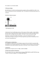
Allowable Antennas to Use with the SiP Module
MDL NRF24L01+ 02 has a straight solid core, 24AWG, 30 +/‐1 mm long wire antenna soldered to
the wire pad labeled ANT1. The antenna serves as a quarter wave monopole in the 2.4GHz band.
There are no additional connectors on the PCB for use with other antennas
Required Regulatory Wording for User Guide
IC statement
This device contains licence‐exempt transmitter(s)/receiver(s) that comply with Innovation,
Science and Economic Development Canada’s licence‐exempt RSS(s). Operation is subject to the
following two conditions:
(1) This device may not cause interference.
(2) This device must accept any interference, including interference that may cause undesired
operation of the device.
The term “IC: “ before the certification/registration number only signifies that the Industry
Canada technical specifications were met.
This product meets the applicable Industry Canada technical specifications.
Cet appareil contient des émetteurs / récepteurs exemptés de licence conformes aux RSS (RSS)
d'Innovation, Sciences et Développement économique Canada. L'exploitation est autorisée aux
deux conditions suivantes :
l'appareil ne doit pas produire de brouillage, et
(2) l'utilisateur de l'appareil doit accepter tout brouillage radioélectrique subi, même si le
brouillage est susceptible d'en compromettre le fonctionnement.
L'émetteur/récepteur exempt de licence contenu dans le présent appareil est conforme aux CNR
d'Innovation, Sciences et Développement économique Canada applicables aux appareils radio
exempts de licence.
Ce produit est conforme aux spécifications techniques applicables d'Industrie Canada.

Please notice that if the ISED certification number is not visible when the module is installed
inside another device, then the outside of the device into which the module is installed o display
a label referring to the enclosed module. This exterior label can use wording such as the
following: “Contains IC: 9314A‐MDLNRF24L01” any similar wording that expresses the same
meaning may be used.
l'appareil hôte doit porter une étiquette donnant le numéro de certification du module
d'Industrie Canada, précédé des mots «Contient un module d'émission », du mot « IC: 9314A‐
MDLNRF24L01 » ou d'une formulation similaire exprimant le même sens, comme suit
The device meets the exemption from the routine evaluation limits in section 2.5 of RSS 102 and
compliance with RSS‐102 RF exposure, users can obtain Canadian information on RF exposure
and compliance.
Le dispositif rencontre l'exemption des limites courantes d'évaluation dans la section 2.5 de RSS
102 etla conformité
à l'exposition de RSS‐102 rf, utilisateurs peut obtenir l'information canadienne surl'exposition et
la conformité de rf.
This transmitter must not be co‐located or operating in conjunction with any other antenna or
transmitter. This equipment should be installed and operated with a minimum distance of 20
centimeters between the radiator and your body.
Cet émetteur ne doit pas être Co‐placé ou ne fonctionnant en même temps qu'aucune autre
antenne ouémetteur. Cet équipement devrait être installé et actionné avec une distance
minimum de 20 centimètres entre le radiateur et votre corps.
FCC Compliance Information
Integrator is reminded to assure that these installation instructions will not be made available to the
end‐user of the final host device.
The final host device, into which this RF Module is integrated, must be labelled with an auxiliary label
stating the FCC ID of the RF Module, such as:
“Contains FCC ID: YZH MDLNRF24L0102
This device complies with part 15 of the FCC rules. Operation is subject to the following two conditions:
(1) This device not cause harmful interference and
(2) This device must accept an interference received, including interference that may cause
undesired operation.”
NOTE: This equipment has been tested and found to comply with the limits for a Class B digital device,
pursuant of Part 15 of the FCC Rules. These limits are designed to provide reasonable protection against
harmful interference in a residential installation. This equipment generates, uses, and can radiate radio
frequency energy and, if not installed and used in accordance with the instruction, may cause harmful

interference to radio or television reception, which can be determined by turning the equipment off and
on, the user is encouraged to try to correct the interference by one or more of the following measures:
‐Reorient or relocate the receiving antenna
‐Increase the separation between the equipment and receiver
‐Connect the equipment into an outlet on a circuit different from that to which the receiver is
connected
‐Consult the dealer or an experienced radio/TV technician for help
Changes or modifications to this unit not expressly approved by the party responsible for compliance
could void the user’s authority to operate the equipment.
Module Statement
This single‐modular transmitter is a self‐contained, physically delineated, component for which
compliance can be demonstrated independent of the host operating conditions, and which complies
with all eight requirements of § 15.212(a)(1) as summarized below.
(1) The radio elements have the radio frequency circuitry shielded.
(2) The module has buffered modulation/data inputs to ensure that the device will comply
with Part 15 requirements with any type of input signal.
(3) The module contains power supply regulation on the module.
(4) The module contains a permanently attached antenna.
(5) The module demonstrates compliance in a stand‐alone configuration.
(6) The module is labeled with its permanently affixed FCC ID label
(7) The module complies with all specific rules applicable to the transmitter, including all
the conditions provided in the integration instructions by the grantee.
(8) The module complies with RF exposure requirements.
The transmitter/module must not be collocated or operating in conjunction with any other antenna or
transmitter.
Module Integration Instructions
Integration instructions for host product manufacturers according to KDB 996369 D03 OEM
Manual v01
2.2 List of applicable FCC rules
FCC Part 15.249
2.3 Specific operational use conditions
For use with other modules of this type, where one or more device is a primary transmitter and
one or more device is a primary receiver. For operation only in the band 2.4046‐2.4796 GHz.
2.4 Limited module procedures

This module is not a limited module
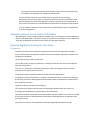
2.5 Antenna designs
MDL NRF24L01+ 02 shall be manufactured with a straight, solid core, 24AWG wire 30+/‐1mm
long, and soldered into the wire pad labeled “ANT1” on the Board. PCB layout specifications are
as follows:
A deviation(s) from the defined parameters of the antenna of either module, as described by
the instructions, require that the host product manufacturer must notify the module grantee
that they wish to change the antenna design. In this case, a Class II permissive change
application is required to be filed by the grantee, or the host manufacturer can take
responsibility through the change in FCC ID (new application) procedure followed by a Class II
permissive change application.
2.6 RF exposure considerations
This equipment complies with FCC RF radiation exposure limits set forth for an uncontrolled
environment, for a minimum separation of 5mm between antenna and body. The host product
manufacturer will provide the above information to end users in their end‐product manuals.
2.7 Antennas
Quarter wave monopole antenna; 5.19dBi; 2.4046‐2.4796GHz
2.8 Label and compliance information
The end product must carry a physical label, following KDB784748D01 and KDB 784748 stating
“Contains Transmitter Module FCC ID:YZHMDLNRF24L0102”.

2.9 Information on test modes and additional testing requirements
To test the module as a standalone unmodulated constant carrier, refer to Appendix C in
“nRF24L01+ Product Specification.pdf” which is supplied along with this document
As noted in Appendix C, the nRF24L01+ IC requires communication via the SPI lines on the IC.
These are routed to the module connection pins.
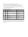
The pin definitions are as follows:
Pin Name SPI Function Specifications
W1 Vdd Power supply for IC Supply must be 1.9‐3.6V DC
W2 GND GND
W3 CE N/A Chip Enable, not used for SPI
communication
W4 CSN Slave Select, Active Low Pull low to enable
communication with this
device
W5 SCK SPI Clock
W6 MOSI Master Out Slave In for SPI
communication
MDL NRF24L01+ 02 is the
slave device
W7 MISO Master In Slave Out for SPI
communication
MDL NRF24L01+ 02 is the
slave device
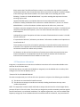
W8 IRQ N/A Interrupt
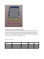
A 3D representation similar MDL NRF24L01+ 02 is below. The pin locations of MDL NRF24L01+
02 are identical to this representation. The pin locations on the module are from W1 through
W8 as follows:

2.10 Additional testing, Part 15 Subpart B disclaimer
The modular transmitter is only FCC authorized for the specific rule parts (FCC Part 15.249)
listed on the grant, and that the host product manufacturer is responsible for compliance to
any other FCC rules that apply to the host not covered by the modular transmitter grant of
certification. The final host product still requires Part 15 Subpart B compliance testing with the
modular transmitter installed if it contains digital circuity.
Document History
Document
Revision
Change description Engineer Engineer Peer‐
Review
Date
REV A Initial Release Dylan Klepps 9/2/2020
-
 1
1
-
 2
2
-
 3
3
-
 4
4
-
 5
5
-
 6
6
-
 7
7
-
 8
8


RAFFEL MDLNRF24L01+ 02 Module Manuel utilisateur
- Taper
- Manuel utilisateur
dans d''autres langues
Autres documents
-
thinkcar ThinkDiag Manuel utilisateur
-
Continental A3C108397 Manuel utilisateur
-
Sengled MX1290 Manuel utilisateur
-
Hisense AEH-W0G2 Guide d'installation
-
 DALS Lighting DCPLSCA 6 iNCH Regressed Gimbal Downlight Manuel utilisateur
-
ARI UNI42 Mode d'emploi
-
Grundfos SCALA1 Integration Manual
-
 Espressif ESP32-S3-MINI-1 Manuel utilisateur
-
GSD WXT2F Manuel utilisateur
-
GSD DT3AR1501 Manuel utilisateur

