Espressif ESP32-S3-MINI-1 Manuel utilisateur
- Catégorie
- Antennes réseau
- Taper
- Manuel utilisateur

ESP32-S3-MINI-1
ESP32-S3-MINI-1U
User Manual
Small-sized module supporting 2.4 GHz Wi-Fi (802.11 b/g/n) and Bluetooth®5 (LE)
Built around ESP32-S3 series of SoCs, Xtensa®dual-core 32-bit LX7 microprocessor
8 MB flash
39 GPIOs, rich set of peripherals
On-board PCB antenna or external antenna connector
ESP32-S3-MINI-1 ESP32-S3-MINI-1U
Pre-release v0.6
Espressif Systems
Copyright © 2022
www.espressif.com

1 Module Overview
1 Module Overview
1.1 Features
CPU and On-Chip Memory
• ESP32-S3FN8 embedded, Xtensa®dual-core
32-bit LX7 microprocessor, up to 240 MHz
• 384 KB ROM
• 512 KB SRAM
• 16 KB SRAM in RTC
• 8 MB SPI flash
Wi-Fi
• 802.11 b/g/n
• Bit rate: 802.11n up to 150 Mbps
• A-MPDU and A-MSDU aggregation
• 0.4 µs guard interval support
• Center frequency range of operating channel:
2412 ~2462 MHz
Bluetooth
• Bluetooth LE: Bluetooth 5, Bluetooth mesh
• Speed: 125 Kbps, 500 Kbps, 1 Mbps, 2 Mbps
• Advertising extensions
• Multiple advertisement sets
• Channel selection algorithm #2
Peripherals
• GPIO, SPI, LCD interface, Camera interface,
UART, I2C, I2S, remote control, pulse counter,
LED PWM, USB 1.1 OTG, USB Serial/JTAG
controller, MCPWM, SDIO host, GDMA, TWAI®
controller (compatible with ISO 11898-1, i.e.
CAN Specification 2.0), ADC, touch sensor,
temperature sensor, timers and watchdogs
Integrated Components on Module
• 40 MHz crystal oscillator
Antenna Options
• On-board PCB antenna
(ESP32-S3-MINI-1)
• External antenna via a connector
(ESP32-S3-MINI-1U)
Operating Conditions
• Operating voltage/Power supply: 3.0 ~3.6 V
• Operating ambient temperature: –40 ~85 °C
1.2 Description
ESP32-S3-MINI-1 and ESP32-S3-MINI-1U are two powerful, generic Wi-Fi + Bluetooth LE MCU modules that
feature a rich set of peripherals, yet an optimized size. They are an ideal choice for a wide variety of application
scenarios related to Internet of Things (IoT), such as embedded systems, smart home, wearable electronics,
etc.
ESP32-S3-MINI-1 comes with a PCB antenna. ESP32-S3-MINI-1U comes with an external antenna connector.
The ordering information of the module is shown in Table 1.
The information in this datasheet is applicable to both modules.
Espressif Systems 2
Submit Documentation Feedback
ESP32-S3-MINI-1 & MINI-1U User Manual v0.6

1 Module Overview
Table 1: Ordering Information
Module ESP32-S3-MINI-1 ESP32-S3-MINI-1U
Variants ESP32-S3-MINI-1-N8 ESP32-S3-MINI-1U-N8
Chip Embedded ESP32-S3FN8
Flash 8 MB (Quad SPI)
PSRAM 0
Dimensions 15.4 × 20.5 × 2.4 15.4 × 15.4 × 2.4
At the core of the modules is an ESP32-S3FN8, an Xtensa® 32-bit LX7 CPU that operates at up to 240 MHz.
You can power off the CPU and make use of the low-power co-processor to constantly monitor the peripherals
for changes or crossing of thresholds.
ESP32-S3FN8 integrates a rich set of peripherals including SPI, LCD, Camera interface, UART, I2C, I2S, remote
control, pulse counter, LED PWM, USB Serial/Jtag, MCPWM, SDIO host, GDMA, TWAI®controller (compatible
with ISO 11898-1, i.e. CAN Specification 2.0), ADC, touch sensor, temperature sensor, timers and watchdogs,
as well as up to 45 GPIOs. It also includes a full-speed USB 1.1 On-The-Go (OTG) interface to enable USB
communication.
Note:
* For more information on ESP32-S3FN8, please refer to ESP32-S3 Series Datasheet .
Espressif Systems 3
Submit Documentation Feedback
ESP32-S3-MINI-1 & MINI-1U User Manual v0.6

Contents
Contents
1 Module Overview 2
1.1 Features 2
1.2 Description 2
2 Pin Definitions 5
2.1 Pin Layout 5
2.2 Pin Description 5
3 Get Started 8
3.1 What You Need 8
3.2 Hardware Connection 8
3.3 Set up Development Environment 9
3.3.1 Install Prerequisites 9
3.3.2 Get ESP-IDF 9
3.3.3 Set up Tools 10
3.3.4 Set up Environment Variables 10
3.4 Create Your First Project 10
3.4.1 Start a Project 10
3.4.2 Connect Your Device 10
3.4.3 Configure 11
3.4.4 Build the Project 11
3.4.5 Flash onto the Device 12
3.4.6 Monitor 13
4 U.S. FCC Statement 15
5 Industry Canada Statement 19
6 Related Documentation and Resources 22
Revision History 23
Espressif Systems 4
Submit Documentation Feedback
ESP32-S3-MINI-1 & MINI-1U User Manual v0.6

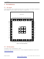
2 Pin Definitions
2 Pin Definitions
2.1 Pin Layout
The pin diagram below shows the approximate location of pins on the module. The pin diagram is applicable for
ESP32-S3-MINI-1 and ESP32-S3-MINI-1U, but the latter has no keepout zone.
Pin 1
Pin 2
Pin 3
Pin 4
Pin 5
Pin 6
Pin 7
Pin 8
Pin 9
Pin 10
Pin 11
Pin 12
Pin 13
Pin 14
Pin 15
GND
GND
3V3
IO0
IO1
IO2
IO3
IO4
IO5
IO6
IO7
IO8
IO9
IO10
IO11
Pin 63
GND
IO12 Pin 16
Pin 17
Pin 18
Pin 19
Pin 20
Pin 21
Pin 22
Pin 23
Pin 24
Pin 25
Pin 26
Pin 27
Pin 28
Pin 29
Pin 30
Pin 64
GND
Pin 31
IO13
IO14
IO15
IO16
IO17
IO18
IO19
IO20
IO21
IO26
IO47
IO33
IO34
IO48
Pin 32
Pin 33
Pin 34
Pin 35
Pin 36
Pin 37
Pin 38
Pin 39
Pin 40
Pin 41
Pin 42
Pin 43
Pin 44
Pin 45
Pin 65
GND
Pin 62
GND
Pin 46
Pin 47
Pin 48
Pin 49
Pin 50
Pin 51
Pin 52
Pin 53
Pin 54
Pin 55
Pin 56
Pin 57
Pin 58
Pin 59
Pin 60
Pin 61
GND
GND GND GND
GND
GND
GND GND GND
IO35
IO36
IO37
IO38
IO39
IO40
IO41
IO42
TXD0
RXD0
IO45
GND
GND
IO46
EN
GND
GND
GND
GND
GND
GND
GND
GND
GND
GND
GND
GND
GND
GND
GND
Keepout Zone
Figure 1: Pin Layout (Top View)
2.2 Pin Description
The module has 65 pins. See pin definitions in Table 2.
For explanations of pin names and function names, as well as configurations of peripheral pins, please refer to
ESP32-S3 Series Datasheet .
Espressif Systems 5
Submit Documentation Feedback
ESP32-S3-MINI-1 & MINI-1U User Manual v0.6

2 Pin Definitions
Table 2: Pin Definitions
Name No. Type aFunction
GND 1, 2, 42, 43, 46-65 P GND
3V3 3 P Power supply
IO0 4 I/O/T RTC_GPIO0, GPIO0
IO1 5 I/O/T RTC_GPIO1, GPIO1, TOUCH1, ADC1_CH0
IO2 6 I/O/T RTC_GPIO2, GPIO2, TOUCH2, ADC1_CH1
IO3 7 I/O/T RTC_GPIO3, GPIO3, TOUCH3, ADC1_CH2
IO4 8 I/O/T RTC_GPIO4, GPIO4, TOUCH4, ADC1_CH3
IO5 9 I/O/T RTC_GPIO5, GPIO5, TOUCH5, ADC1_CH4
IO6 10 I/O/T RTC_GPIO6, GPIO6, TOUCH6, ADC1_CH5
IO7 11 I/O/T RTC_GPIO7, GPIO7, TOUCH7, ADC1_CH6
IO8 12 I/O/T RTC_GPIO8, GPIO8, TOUCH8, ADC1_CH7, SUBSPICS1
IO9 13 I/O/T RTC_GPIO9, GPIO9, TOUCH9, ADC1_CH8, FSPIHD, SUBSPIHD
IO10 14 I/O/T RTC_GPIO10, GPIO10, TOUCH10, ADC1_CH9, FSPICS0, FSPIIO4,
SUBSPICS0
IO11 15 I/O/T RTC_GPIO11, GPIO11, TOUCH11, ADC2_CH0, FSPID, FSPIIO5,
SUBSPID
IO12 16 I/O/T RTC_GPIO12, GPIO12, TOUCH12, ADC2_CH1, FSPICLK, FSPIIO6,
SUBSPICLK
IO13 17 I/O/T RTC_GPIO13, GPIO13, TOUCH13, ADC2_CH2, FSPIQ, FSPIIO7,
SUBSPIQ
IO14 18 I/O/T RTC_GPIO14, GPIO14, TOUCH14, ADC2_CH3, FSPIWP, FSPIDQS,
SUBSPIWP
IO15 19 I/O/T RTC_GPIO15, GPIO15, U0RTS, ADC2_CH4, XTAL_32K_P
IO16 20 I/O/T RTC_GPIO16, GPIO16, U0CTS, ADC2_CH5, XTAL_32K_N
IO17 21 I/O/T RTC_GPIO17, GPIO17, U1TXD, ADC2_CH6
IO18 22 I/O/T RTC_GPIO18, GPIO18, U1RXD, ADC2_CH7, CLK_OUT3
IO19 23 I/O/T RTC_GPIO19, GPIO19, U1RTS, ADC2_CH8, CLK_OUT2, USB_D-
IO20 24 I/O/T RTC_GPIO20, GPIO20, U1CTS, ADC2_CH9, CLK_OUT1, USB_D+
IO21 25 I/O/T RTC_GPIO21, GPIO21
IO26 26 I/O/T SPICS1, GPIO26
IO47 27 I/O/T SPICLK_P_DIFF, GPIO47, SUBSPICLK_P_DIFF
IO33 28 I/O/T SPIIO4, GPIO33, FSPIHD, SUBSPIHD
IO34 29 I/O/T SPIIO5, GPIO34, FSPICS0, SUBSPICS0
IO48 30 I/O/T SPICLK_N_DIFF, GPIO48, SUBSPICLK_N_DIFF
IO35 31 I/O/T SPIIO6, GPIO35, FSPID, SUBSPID
IO36 32 I/O/T SPIIO7, GPIO36, FSPICLK, SUBSPICLK
IO37 33 I/O/T SPIDQS, GPIO37, FSPIQ, SUBSPIQ
IO38 34 I/O/T GPIO38, FSPIWP, SUBSPIWP
IO39 35 I/O/T MTCK, GPIO39, CLK_OUT3, SUBSPICS1
IO40 36 I/O/T MTDO, GPIO40, CLK_OUT2
IO41 37 I/O/T MTDI, GPIO41, CLK_OUT1
Cont’d on next page
Espressif Systems 6
Submit Documentation Feedback
ESP32-S3-MINI-1 & MINI-1U User Manual v0.6

2 Pin Definitions
Table 2 – cont’d from previous page
Name No. Type aFunction
IO42 38 I/O/T MTMS, GPIO42
TXD0 39 I/O/T U0TXD, GPIO43, CLK_OUT1
RXD0 40 I/O/T U0RXD, GPIO44, CLK_OUT2
IO45 41 I/O/T GPIO45
IO46 44 I/O/T GPIO46
EN 45 I
High: on, enables the chip.
Low: off, the chip powers off.
Note: Do not leave the EN pin floating.
aP: power supply; I: input; O: output; T: high impedance. Pin functions in bold font are the default pin functions.
For pin 28 ∼29, 31 ∼33, the default function is decided by eFuse bit.
Espressif Systems 7
Submit Documentation Feedback
ESP32-S3-MINI-1 & MINI-1U User Manual v0.6

3 Get Started
3 Get Started
3.1 What You Need
To develop applications for module you need:
• 1 x ESP32-S3-MINI-1 or ESP32-S3-MINI-1U
• 1 x Espressif RF testing board
• 1 x USB-to-Serial board
• 1 x Micro-USB cable
• 1 x PC running Linux
In this user guide, we take Linux operating system as an example. For more information about the configuration
on Windows and macOS, please refer to ESP-IDF Programming Guide.
3.2 Hardware Connection
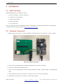
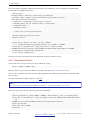
1. Solder the ESP32-S3-MINI-1 or ESP32-S3-MINI-1U module to the RF testing board as shown in Figure 2.
Figure 2: Hardware Connection
2. Connect the RF testing board to the USB-to-Serial board via TXD, RXD, and GND.
3. Connect the USB-to-Serial board to the PC.
4. Connect the RF testing board to the PC or a power adapter to enable 5 V power supply, via the Micro-USB
cable.
5. During download, connect IO0 to GND via a jumper. Then, turn ”ON” the testing board.
6. Download firmware into flash. For details, see the sections below.
Espressif Systems 8
Submit Documentation Feedback
ESP32-S3-MINI-1 & MINI-1U User Manual v0.6

3 Get Started
7. After download, remove the jumper on IO0 and GND.
8. Power up the RF testing board again. The module will switch to working mode. The chip will read
programs from flash upon initialization.
Note:
IO0 is internally logic high. If IO0 is set to pull-up, the Boot mode is selected. If this pin is pull-down or left floating,
the Download mode is selected. For more information on ESP32-S3-MINI-1 or ESP32-S3-MINI-1U, please refer to
ESP32-S3 Series Datasheet .
3.3 Set up Development Environment
The Espressif IoT Development Framework (ESP-IDF for short) is a framework for developing applications based
on the Espressif ESP32. Users can develop applications with ESP32-S3 in Windows/Linux/macOS based on
ESP-IDF. Here we take Linux operating system as an example.
3.3.1 Install Prerequisites
To compile with ESP-IDF you need to get the following packages:
• CentOS 7 & 8:
1sudo yum -y update && sudo yum install git wget flex bison gperf python3 python3-
pip
2python3-setuptools cmake ninja-build ccache dfu-util libusbx
• Ubuntu and Debian:
1sudo apt-get install git wget flex bison gperf python3 python3-pip python3-
setuptools
2cmake ninja-build ccache libffi-dev libssl-dev dfu-util libusb-1.0-0
• Arch:
1sudo pacman -S --needed gcc git make flex bison gperf python-pip cmake ninja
ccache
2dfu-util libusb
Note:
• This guide uses the directory ~/esp on Linux as an installation folder for ESP-IDF.
• Keep in mind that ESP-IDF does not support spaces in paths.
3.3.2 Get ESP-IDF
To build applications for ESP32-S3-MINI-1 or ESP32-S3-MINI-1U module, you need the software libraries
provided by Espressif in ESP-IDF repository.
To get ESP-IDF, create an installation directory (~/esp) to download ESP-IDF to and clone the repository with ‘git
clone’:
Espressif Systems 9
Submit Documentation Feedback
ESP32-S3-MINI-1 & MINI-1U User Manual v0.6

3 Get Started
1mkdir -p ~/esp
2cd ~/esp
3git clone --recursive https://github.com/espressif/esp-idf.git
ESP-IDF will be downloaded into ~/esp/esp-idf. Consult ESP-IDF Versions for information about which ESP-IDF
version to use in a given situation.
3.3.3 Set up Tools
Aside from the ESP-IDF, you also need to install the tools used by ESP-IDF, such as the compiler, debugger,
Python packages, etc. ESP-IDF provides a script named ’install.sh’ to help set up the tools in one go.
1cd ~/esp/esp-idf
2./install.sh
3.3.4 Set up Environment Variables
The installed tools are not yet added to the PATH environment variable. To make the tools usable from the
command line, some environment variables must be set. ESP-IDF provides another script ’export.sh’ which does
that. In the terminal where you are going to use ESP-IDF, run:
1. $HOME/esp/esp-idf/export.sh
Now everything is ready, you can build your first project on ESP32-S3-MINI-1 or ESP32-S3-MINI-1U
module.
3.4 Create Your First Project
3.4.1 Start a Project
Now you are ready to prepare your application for ESP32-S3-MINI-1 or ESP32-S3-MINI-1U module. You can
start with get-started/hello_world project from examples directory in ESP-IDF.
Copy get-started/hello_world to ~/esp directory:
1cd ~/esp
2cp -r $IDF_PATH/examples/get-started/hello_world .
There is a range of example projects in the examples directory in ESP-IDF. You can copy any project in the same
way as presented above and run it. It is also possible to build examples in-place, without copying them
first.
3.4.2 Connect Your Device
Now connect your module to the computer and check under what serial port the module is visible. Serial ports in
Linux start with ‘/dev/tty’ in their names. Run the command below two times, first with the board unplugged,
then with plugged in. The port which appears the second time is the one you need:
1ls /dev/tty*
Espressif Systems 10
Submit Documentation Feedback
ESP32-S3-MINI-1 & MINI-1U User Manual v0.6

3 Get Started
Note:
Keep the port name handy as you will need it in the next steps.
3.4.3 Configure
Navigate to your ‘hello_world’ directory from Step 3.4.1. Start a Project, set ESP32-S3 chip as the target and run
the project configuration utility ‘menuconfig’.
1cd ~/esp/hello_world
2idf.py set-target esp32s3
3idf.py menuconfig
Setting the target with ‘idf.py set-target ESP32-S3’ should be done once, after opening a new project. If the
project contains some existing builds and configuration, they will be cleared and initialized. The target may be
saved in environment variable to skip this step at all. See Selecting the Target for additional information.
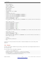
If the previous steps have been done correctly, the following menu appears:
Figure 3: Project Configuration - Home Window
You are using this menu to set up project specific variables, e.g. Wi-Fi network name and password, the
processor speed, etc. Setting up the project with menuconfig may be skipped for “hello_word”. This example will
run with default configuration
The colors of the menu could be different in your terminal. You can change the appearance with the option
‘-�-style’�. Please run ‘idf.py menuconfig -�-help’�for further information.
3.4.4 Build the Project
Build the project by running:
1idf.py build
Espressif Systems 11
Submit Documentation Feedback
ESP32-S3-MINI-1 & MINI-1U User Manual v0.6

3 Get Started
This command will compile the application and all ESP-IDF components, then it will generate the bootloader,
partition table, and application binaries.
1$ idf.py build
2Running cmake in directory /path/to/hello_world/build
3Executing ”cmake -G Ninja --warn-uninitialized /path/to/hello_world”...
4Warn about uninitialized values.
5-- Found Git: /usr/bin/git (found version ”2.17.0”)
6-- Building empty aws_iot component due to configuration
7-- Component names: ...
8-- Component paths: ...
9
10 ... (more lines of build system output)
11
12 [527/527] Generating hello_world.bin
13 esptool.py v2.3.1
14
15 Project build complete. To flash, run this command:
16 ../../../components/esptool_py/esptool/esptool.py -p (PORT) -b 921600
17 write_flash --flash_mode dio --flash_size detect --flash_freq 40m
18 0x10000 build/hello_world.bin build 0x1000 build/bootloader/bootloader.bin 0x8000
19 build/partition_table/partition-table.bin
20 or run ’idf.py -p PORT flash’
If there are no errors, the build will finish by generating the firmware binary .bin file.
3.4.5 Flash onto the Device
Flash the binaries that you just built onto your module by running:
1idf.py -p PORT [-b BAUD] flash
Replace PORT with your ESP32-S3 board’s serial port name from Step: Connect Your Device.
You can also change the flasher baud rate by replacing BAUD with the baud rate you need. The default baud
rate is 460800.
For more information on idf.py arguments, see idf.py.
Note:
The option ‘flash‘ automatically builds and flashes the project, so running ‘idf.py build‘ is not necessary.
When flashing, you will see the output log similar to the following:
1...
2esptool.py esp32s3 -p /dev/ttyUSB0 -b 460800 --before=default_reset --after=hard_reset
3write_flash --flash_mode dio --flash_freq 80m --flash_size 2MB 0x0 bootloader/bootloader.
bin
40x10000 hello_world.bin 0x8000 partition_table/partition-table.bin
5esptool.py v3.2-dev
6Serial port /dev/ttyUSB0
7Connecting....
Espressif Systems 12
Submit Documentation Feedback
ESP32-S3-MINI-1 & MINI-1U User Manual v0.6

3 Get Started
8Chip is ESP32-S3
9Features: WiFi, BLE
10 Crystal is 40MHz
11 MAC: 7c:df:a1:e0:00:64
12 Uploading stub...
13 Running stub...
14 Stub running...
15 Changing baud rate to 460800
16 Changed.
17 Configuring flash size...
18 Flash will be erased from 0x00000000 to 0x00004fff...
19 Flash will be erased from 0x00010000 to 0x00039fff...
20 Flash will be erased from 0x00008000 to 0x00008fff...
21 Compressed 18896 bytes to 11758...
22 Writing at 0x00000000... (100 %)
23 Wrote 18896 bytes (11758 compressed) at 0x00000000 in 0.5 seconds (effective 279.9 kbit/s)
...
24 Hash of data verified.
25 Compressed 168208 bytes to 88178...
26 Writing at 0x00010000... (16 %)
27 Writing at 0x0001a80f... (33 %)
28 Writing at 0x000201f1... (50 %)
29 Writing at 0x00025dcf... (66 %)
30 Writing at 0x0002d0be... (83 %)
31 Writing at 0x00036c07... (100 %)
32 Wrote 168208 bytes (88178 compressed) at 0x00010000 in 2.4 seconds (effective 569.2 kbit/s
)...
33 Hash of data verified.
34 Compressed 3072 bytes to 103...
35 Writing at 0x00008000... (100 %)
36 Wrote 3072 bytes (103 compressed) at 0x00008000 in 0.1 seconds (effective 478.9 kbit/s)...
37 Hash of data verified.
38
39 Leaving...
40 Hard resetting via RTS pin...
41 Done
If there are no issues by the end of the flash process, the board will reboot and start up the “hello_world”
application.
3.4.6 Monitor
To check if “hello_world” is indeed running, type ‘idf.py -p PORT monitor‘ (Do not forget to replace PORT with
your serial port name).
This command launches the IDF Monitor application:
1$ idf.py -p /dev/ttyUSB0 monitor
2Running idf_monitor in directory [...]/esp/hello_world/build
3Executing ”python [...]/esp-idf/tools/idf_monitor.py -b 115200
4[...]/esp/hello_world/build/hello-world.elf”...
Espressif Systems 13
Submit Documentation Feedback
ESP32-S3-MINI-1 & MINI-1U User Manual v0.6

3 Get Started
5--- idf_monitor on /dev/ttyUSB0 115200 ---
6--- Quit: Ctrl+] | Menu: Ctrl+T | Help: Ctrl+T followed by Ctrl+H ---
7ets Jun 8 2016 00:22:57
8
9rst:0x1 (POWERON_RESET),boot:0x13 (SPI_FAST_FLASH_BOOT)
10 ets Jun 8 2016 00:22:57
11 ...
After startup and diagnostic logs scroll up, you should see “Hello world!” printed out by the application.
1...
2Hello world!
3Restarting in 10 seconds...
4This is esp32s3 chip with 2 CPU core(s), This is esp32s3 chip with 2 CPU core(s), WiFi/BLE
,
5silicon revision 0, 2MB external flash
6Minimum free heap size: 390684 bytes
7Restarting in 9 seconds...
8Restarting in 8 seconds...
9Restarting in 7 seconds...
To exit IDF monitor use the shortcut Ctrl+].
That’s all what you need to get started with ESP32-S3-MINI-1 or ESP32-S3-MINI-1U module! Now you are
ready to try some other examples in ESP-IDF, or go right to developing your own applications.
Espressif Systems 14
Submit Documentation Feedback
ESP32-S3-MINI-1 & MINI-1U User Manual v0.6

4 U.S. FCC Statement
4 U.S. FCC Statement
The devices comply with KDB 996369 D03 OEM Manual v01. Below are integration instructions for host product
manufacturers according to the KDB 996369 D03 OEM Manual v01.
List of Applicable FCC Rules
FCC Part 15 Subpart C 15.247 & 15.209
Specific Operational Use Conditions
The modules have WiFi, BR, EDR, and BLE functions.
• Operation Frequency:
–WiFi: 2412 ~2462 MHz
–Bluetooth: 2402 ~2480 MHz
• Number of Channel:
–WiFi: 12
–Bluetooth: 40
• Modulation:
–WiFi: DSSS; OFDM
–Bluetooth: GFSK; π/4 DQPSK; 8 DPSK
• Type: On-board PCB antenna or external antenna connector
• Gain: 4.54 dBi Max
The modules can be used for IoT applications with a maximum 3.96 dBi antenna. The host manufacturer
installing the modules into their product must ensure that the final composit product complies with the FCC
requirements by a technical assessment or evaluation to the FCC rules, including the transmitter operation. The
host manufacturer has to be aware not to provide information to the end user regarding how to install or remove
the RF modules in the user’s manual of the end product which integrates the modules. The end user manual shall
include all required regulatory information/warning as show in this manual.
Limited Module Procedures
Not applicable. The modules are single modules and comply with the requirement of FCC Part 15.212.
Trace Antenna Designs
Not applicable. The modules have their own antenna, and do not need a host’s printed board microstrip trace
antenna, etc.
RF Exposure Considerations
The modules must be installed in the host equipment such that at least 20cm is maintained between the antenna
and users’ body; and if RF exposure statement or module layout is changed, then the host product manufacturer
Espressif Systems 15
Submit Documentation Feedback
ESP32-S3-MINI-1 & MINI-1U User Manual v0.6

4 U.S. FCC Statement
required to take responsibility of the modules through a change in FCC ID or new application. The FCC ID of the
modules cannot be used on the final product. In these circumstances, the host manufacturer will be responsible
for re-evaluating the end product (including the transmitter) and obtaining a separate FCC authorization.
Antennas
Antenna specification are as follows:
• Type: On-board PCB antenna
• Gain: 3.96 dBi
• Type: External antenna connector
• Gain: 4.54 dBi
This device is intended only for host manufacturers under the following conditions:
• The transmitter module may not be co-located with any other transmitter or antenna.
• The modules shall be only used with the external antenna(s) that has been originally tested and certified
with the modules.
• The antenna must be either permanently attached or employ a ‘unique’ antenna coupler.
As long as the conditions above are met, further transmitter test will not be required. However, the host
manufacturer is still responsible for testing their end-product for any additional compliance requirements required
with the modules installed (for example, digital device emissions, PC peripheral requirements, etc.).
Label and Compliance Information
Host product manufacturers need to provide a physical or e-label stating “Contains FCC ID:
2AC7Z-ESPS3MINI1” with their finished product.
Information on test modes and additional testing requirements
• Operation Frequency:
–WiFi: 2412 ~2462 MHz
–Bluetooth: 2402 ~2480 MHz
• Number of Channel:
–WiFi: 12
–Bluetooth: 40
• Modulation:
–WiFi: DSSS; OFDM
–Bluetooth: GFSK; π/4 DQPSK; 8 DPSK
Host manufacturer must perform test of radiated and conducted emission and spurious emission, etc., according
to the actual test modes for a stand-alone modular transmitter in a host, as well as for multiple simultaneously
transmitting modules or other transmitters in a host product. Only when all the test results of test modes comply
with FCC requirements, then the end product can be sold legally.
Espressif Systems 16
Submit Documentation Feedback
ESP32-S3-MINI-1 & MINI-1U User Manual v0.6

4 U.S. FCC Statement
Additional testing, Part 15 Subpart B compliant
The modular transmitter is only FCC authorized for FCC Part 15 Subpart C 15.247 & 15.209 and that the host
product manufacturer is responsible for compliance to any other FCC rules that apply to the host not covered by
the modular transmitter grant of certification. If the grantee markets their product as being Part 15 Subpart B
compliant (when it also contains unintentional-radiator digital circuity), then the grantee shall provide a notice
stating that the final host product still requires Part 15 Subpart B compliance testing with the modular transmitter
installed.
This equipment has been tested and found to comply with the limits for a Class B digital device, pursuant to
Part15 of the FCC Rules. These limits are designed to provide reasonable protection against harmful interference
in a residential installation. This equipment generates, uses and can radiate radio frequency energy and, if not
installed and used in accordance with the instructions, may cause harmful interference to radio
communications.
However, there is no guarantee that interference will not occur in a particular installation. If this equipment does
cause harmful interference to radio or television reception, which can be determined by turning the equipment off
and on, the user is encouraged to try to correct the interference by one of the following measures:
• Reorient or relocate the receiving antenna.
• Increase the separation between the equipment and receiver.
• Connect the equipment into an outlet on a circuit different from that to which the receiver is connected.
• Consult the dealer or an experienced radio/TV technician for help.
The devices comply with Part 15 of the FCC Rules. Operation is subject to the following two conditions:
• This device may not cause harmful interference.
• This device must accept any interference received, including interference that may cause undesired
operation.
Caution:
Any changes or modifications not expressly approved by the party responsible for compliance could void the user’s
authority to operate the equipment.
The equipment complies with FCC RF radiation exposure limits set forth for an uncontrolled environment. This
device and its antenna must not be co-located or operating in conjunction with any other antenna or transmitter.
The antennas used for this transmitter must be installed to provide a separation distance of at least 20 cm from
all persons and must not be co-located or operating in conjunction with any other antenna or transmitter.
OEM Integration Instructions
The devices are intended only for OEM integrators under the following conditions:
• The transmitter module may not be co-located with any other transmitter or antenna.
• The modules shall be only used with the external antenna(s) that has been originally tested and certified
with the modules.
Espressif Systems 17
Submit Documentation Feedback
ESP32-S3-MINI-1 & MINI-1U User Manual v0.6

4 U.S. FCC Statement
As long as the conditions above are met, further transmitter test will not be required. However, the OEM
integrator is still responsible for testing their end-product for any additional compliance requirements required
with the modules installed (for example, digital device emissions, PC peripheral requirements, etc.).
Validity of Using the Module Certification
In the event that these conditions cannot be met (for example certain laptop configurations or co-location with
another transmitter), then the FCC authorization for the modules in combination with the host equipment is no
longer considered valid and the FCC ID of the modules cannot be used on the final product. In these
circumstances, the OEM integrator will be responsible for re-evaluating the end product (including the transmitter)
and obtaining a separate FCC authorization.
End Product Labeling
The final end product must be labeled in a visible area with the following: “Contains Transmitter Module FCC ID:
2AC7Z-ESPS3MINI1”.
Espressif Systems 18
Submit Documentation Feedback
ESP32-S3-MINI-1 & MINI-1U User Manual v0.6

5 Industry Canada Statement
5 Industry Canada Statement
This device complies with Industry Canada’s licence-exempt RSSs. Operation is subject to the following two
conditions:
• This device may not cause interference; and
• This device must accept any interference, including interference that may cause undesired operation of the
device.
Le présent appareil est conforme aux CNR d’Industrie Canada applicables aux appareils radio exempts de
licence. L’exploitation est autorisée aux deux conditions suivantes:
• l’appareil ne doit pas produire de brouillage, et
• l’utilisateur de l’appareil doit accepter tout brouillage radioélectrique subi, même si le brouillage est
susceptible d’en compromettre le fonctionnement.
Radiation Exposure Statement
This equipment complies with IC radiation exposure limits set forth for an uncontrolled environment. This
equipment should be installed and operated with minimum distance 20 cm between the radiator and your
body.
Déclaration d’exposition aux radiations:
Cet équipement est conforme aux limites d’exposition aux rayonnements ISED établies pour un environnement
non contrôlé. Cet équipement doit être installé et utilisé avec un minimum de 20 cm de distance entre la source
de rayonnement et votre corps.
RSS-247 Section 6.4 (5)
The device could automatically discontinue transmission in case of absence of information to transmit, or
operational failure. Note that this is not intended to prohibit transmission of control or signaling information or the
use of repetitive codes where required by the technology.
L’appareil peut interrompre automatiquement la transmission en cas d’absence d’informations à transmettre ou
de panne opérationnelle. Notez que ceci n’est pas destiné à interdire la transmission d’informations de contrôle
ou de signalisation ou l’utilisation de codes répétitifs lorsque cela est requis par la technologie.
This device is intended only for OEM integrators under the following conditions (For module device use):
• The antenna must be installed such that 20 cm is maintained between the antenna and users, and
• The transmitter module may not be co-located with any other transmitter or antenna.
As long as 2 conditions above are met, further transmitter test will not be required. However, the OEM integrator
is still responsible for testing their end-product for any additional compliance requirements required with this
module installed.
Espressif Systems 19
Submit Documentation Feedback
ESP32-S3-MINI-1 & MINI-1U User Manual v0.6

5 Industry Canada Statement
Cet appareil est conçu uniquement pour les intégrateurs OEM dans les conditions suivantes (Pour utilisa-
tion de dispositif module):
• L’antenne doit être installée de telle sorte qu’une distance de 20 cm est respectée entre l’antenne et les
utilisateurs, et
• Le module émetteur peut ne pas être coïmplanté avec un autre émetteur ou antenne.
Tant que les 2 conditions ci-dessus sont remplies, des essais supplémentaires sur l’émetteur ne seront pas
nécessaires. Toutefois, l’intégrateur OEM est toujours responsable des essais sur son produit final pour toutes
exigences de conformité supplémentaires requis pour ce module installé.
IMPORTANT NOTE:
In the event that these conditions can not be met (for example certain laptop configurations or colocation with
another transmitter), then the Canada authorization is no longer considered valid and the IC ID can not be used
on the final product. In these circumstances, the OEM integrator will be responsible for re-evaluating the end
product (including the transmitter) and obtaining a separate Canada authorization.
NOTE IMPORTANTE:
Dans le cas où ces conditions ne peuvent être satisfaites (par exemple pour certaines configurations d’ordinateur
portable ou de certaines co-localisation avec un autre émetteur), l’autorisation du Canada n’est plus considéré
comme valide et l’ID IC ne peut pas être utilisé sur le produit final. Dans ces circonstances, l’intégrateur OEM
sera chargé de réévaluer le produit final (y compris l’émetteur) et l’obtention d’une autorisation distincte au
Canada.
End Product Labeling
This transmitter module is authorized only for use in device where the antenna may be installed such that 20 cm
may be maintained between the antenna and users. The final end product must be labeled in a visible area with
the following: “Contains IC: 21098-ESPS3MINI1”.
Plaque signalétique du produit final
Ce module émetteur est autorisé uniquement pour une utilisation dans un dispositif où l’antenne peut être
installée de telle sorte qu’une distance de 20cm peut être maintenue entre l’antenne et les utilisateurs. Le produit
final doit être étiqueté dans un endroit visible avec l’inscription suivante: ”Contient des IC:
21098-ESPS3MINI1”.
Manual Information to the End User
The OEM integrator has to be aware not to provide information to the end user regarding how to install or remove
this RF module in the user’s manual of the end product which integrates this module. The end user manual shall
include all required regulatory information/warning as show in this manual.
Manuel d’information à l’utilisateur final
L’intégrateur OEM doit être conscient de ne pas fournir des informations à l’utilisateur final quant à la façon
d’installer ou de supprimer ce module RF dans le manuel de l’utilisateur du produit final qui intègre ce module. Le
Espressif Systems 20
Submit Documentation Feedback
ESP32-S3-MINI-1 & MINI-1U User Manual v0.6
La page est en cours de chargement...
La page est en cours de chargement...
La page est en cours de chargement...
La page est en cours de chargement...
-
 1
1
-
 2
2
-
 3
3
-
 4
4
-
 5
5
-
 6
6
-
 7
7
-
 8
8
-
 9
9
-
 10
10
-
 11
11
-
 12
12
-
 13
13
-
 14
14
-
 15
15
-
 16
16
-
 17
17
-
 18
18
-
 19
19
-
 20
20
-
 21
21
-
 22
22
-
 23
23
-
 24
24


Espressif ESP32-S3-MINI-1 Manuel utilisateur
- Catégorie
- Antennes réseau
- Taper
- Manuel utilisateur
dans d''autres langues
Documents connexes
-
Espressif ESP32-C3-Mini-1U General-Purpose Wi-Fi and Bluetooth LE Module Manuel utilisateur
-
 Espressif EK058 2.4 GHz WiFi Bluetooth LE Module Manuel utilisateur
-
Espressif ESP8685-WROOM-05 WiFi and Bluetooth LE Module Manuel utilisateur
-
Espressif ESP32-S3-WROOM-1 Bluetooth Module Manuel utilisateur

Autres documents
-
MOUSER ELECTRONICS RM-2450 Manuel utilisateur
-
 Tele Radio CL-TR600-1 Manuel utilisateur
-
RAFFEL MDLNRF24L01+ 02 Module Manuel utilisateur
-
GREE GRJW05J6 Manuel utilisateur
-
 framework FRANBP0000 Manuel utilisateur
-
LG LAMWBD1 Manuel utilisateur
-
 deako Smart Plug Include Floor Lamps and String Lights Manuel utilisateur
-
Cumberland Legacy Connect (LCRXTX & LCRS485) Le manuel du propriétaire
-
-
Yealink YL430132 Manuel utilisateur


