Losi LOS06000T1 Manuel utilisateur
- Catégorie
- Jouets télécommandés
- Taper
- Manuel utilisateur
Ce manuel convient également à

Instruction Manual
Bedienungsanleitung
Manuel d’utilisation
Manuale di Istruzioni
Scan the QR code and select the Manuals and Support quick links from the
product page for the most up-to-date manual information.
Scannen Sie den QR-Code und wählen Sie auf der Produktseite die Quicklinks
Handbücher und Unterstützung, um die aktuellsten Informationen zu Handbücher.
Scannez le code QR et sélectionnez les liens rapides Manuals and Support sur la
page du produit pour obtenir les informations les plus récentes sur le manuel.
Scannerizzare il codice QR e selezionare i Link veloci Manuali e Supporto dalla
pagina del prodotto per le informazioni manuali più aggiornate.
Created 4/23 451831
LOS06000 / LOS06002

2
EN
Age Recommendation: Not for children under 14 years. This is not a toy.
WARNING: Read the ENTIRE instruction manual to become familiar with the features of the product before operating.
Failure to operate the product correctly can result in damage to the product, personal property and cause serious injury.
This is a sophisticated hobby product. It must be operated with caution and common sense and requires some basic
mechanical ability. Failure to operate this Product in a safe and responsible manner could result in injury or damage to the
product or other property. This product is not intended for use by children without direct adult supervision. Do not use with
incompatible components or alter this product in any way outside of the instructions provided by Horizon Hobby, LLC. This
manual contains instructions for safety, operation and maintenance. It is essential to read and follow all the instructions and
warnings in the manual, prior to assembly, setup or use, in order to operate correctly and avoid damage or serious injury.
NOTICE
All instructions, warranties and other collateral documents are subject to change at the sole discretion of Horizon Hobby,
LLC. For up-to-date product literature, visit horizonhobby.com or towerhobbies.com and click on the support or resources
tab for this product.
As the user of this product, you are solely responsible for operating in a manner that does not endanger yourself and others
or result in damage to the product or property of others.
This model is controlled by a radio signal subject to interference from many sources outside your control. This interference can
cause momentary loss of control, so it is advisable to always keep a safe distance in all directions around your model as this
margin will help avoid collisions or injury.
• Never operate your model with low transmitter batteries.
• Always operate your model in open spaces away from full-
size vehicles, trac and people.
• Never operate the model in the street or in populated
areas for any reason.
• Carefully follow the directions and warnings for this and any
optional support equipment (chargers, rechargeable battery
packs, etc.) you use.
• Keep all chemicals, small parts and anything electrical out
of the reach of children.
• Never lick or place any portion of the model in your mouth
as it could cause serious injury or even death.
• Exercise caution when using tools and sharp instruments.
• Take care during maintenance as some parts may have
sharp edges.
• Immediately after using your model, do NOT touch
equipment such as the motor, electronic speed control and
battery, because they generate high temperatures. You
may burn yourself seriously touching them.
• Do not put fingers or any objects inside rotating and
moving parts, as this may cause damage or serious injury.
• Always turn on your transmitter before you turn on the
receiver in the car. Always turn o the receiver before
turning your transmitter o.
• Keep the wheels of the model o the ground when
checking the operation of the radio equipment.
SAFETY PRECAUTIONS AND WARNINGS
WARNING AGAINST COUNTERFEIT PRODUCTS: Always purchase from a Horizon Hobby, LLC authorized dealer to
ensure authentic high-quality Spektrum product. Horizon Hobby, LLC disclaims all support and warranty with regards,
but not limited to, compatibility and performance of counterfeit products or products claiming compatibility with DSM® or
Spektrum technology.
MEANING OF SPECIAL LANGUAGE
The following terms are used throughout the product literature to indicate various levels of potential harm when operating
this product:
WARNING: Procedures, which if not properly followed, create the probability of property damage, collateral damage, and
serious injury OR create a high probability of superficial injury.
CAUTION: Procedures, which if not properly followed, create the probability of physical property damage AND a possibility
of serious injury.
NOTICE: Procedures, which if not properly followed, create a possibility of physical property damage AND a little or no
possibility of injury.

3
EN
TABLE OF CONTENTS
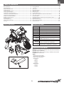
BOX CONTENTS SPECIFICATIONS
REQUIRED EQUIPMENT
included with LOS06002
Box Contents ............................................................................................3
Specifications ..........................................................................................3
Required Equipment ..............................................................................3
Vehicle Parts ............................................................................................. 4
Transmitter Functions ..........................................................................4
Charging Warnings .................................................................................5
Charge the Vehicle Battery .................................................................5
Install the Transmitter Batteries ....................................................... 6
Install the Vehicle Battery ...................................................................6
Power On the Transmitter .................................................................... 7
Power On the Vehicle .............................................................................7
Steering Test ............................................................................................ 7
Flywheel Startup .....................................................................................8
Transmitter Controls .............................................................................8
Driving .........................................................................................................9
Driving Modes ........................................................................................10
Jumping ....................................................................................................10
Run Time ................................................................................................... 11
MX Start Stand ....................................................................................... 11
After Your Run ........................................................................................ 12
Maintenance ........................................................................................... 12
Limited Warranty ..................................................................................14
Warranty and Service Contact Information ................................ 15
FCC Information..................................................................................... 16
IC Information .........................................................................................16
Compliance Information for the European Union .....................16
Exploded Views ..................................................................................... 59
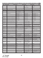
Replacement Parts .............................................................................64
Recommended Parts.......................................................................... 67
Optional Parts ........................................................................................ 67
Scale 1/4
Length 20.2 in (512mm)
Width 10.8 in (274mm)
Height 17.3 in (439mm)
Weight 123.5 oz (3500g)
Motor 3800Kv, 4 pole, Sensorless Brushless
ESC Firma® 85A Brushless Smart Motorcycle ESC
Receiver Spektrum™ DSMR 6CH Receiver
Servos Steering: S620PM Metal Gear Servo
Brake: SX108PM Micro Gear Servo
Transmitter Spektrum™ DX3PM, 3 Channel
Battery 7.4V 5000mAh 2S 50C LiPo, IC5, G2 Smart
Battery (included with LOS06002)
Charger S120 USB-C Smart Charger 1x20W
(included with LOS06002) or equivalent
Battery: 7.4V 5000mAh 2S 50C LiPo, IC5, G2 Smart Battery
(included with LOS06002)
Charger: S120 USB-C Smart Charger 1x20W (included with
LOS06002) or equivalent
Tools:
• Shock Tools (included)
• Fork Tools (x2) (included)
• Chain Lube (included)
• Hex Drivers
- .050in
- 1.5mm
- 2.0mm
- 2.5mm
• Nut Drivers
- 5.0mm
- 5.5mm
- 7.0mm

4
EN
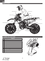
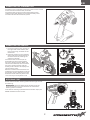
VEHICLE PARTS
TRANSMITTER FUNCTIONS
1
2
3
4
5
6
78 9 10
14
11
12
13
Battery
Drive Chain
Shock Absorber
Rear Sprocket
Battery Connector
Motor
Swing ArmFlywheel
Brake Caliper
Brake Cable
Floating Brake Disc
Receiver
Steering Servo Brake Servo
Fork
Electronic Speed
Control (ESC)
FUNCTION
1 Power Button
2 MS6X Gain Knob
3 LED Indicator
4 Throttle Limit Switch
5 Flywheel Switch
6 Smart Battery Level
7 Steering Reverse Switch
8 Front Brake Travel
9 Steering Sub Trim
10 Front Brake Trim
11 Throttle/Brake Trigger
12 Bind Button
13 Drive Mode Button
14 Steering Wheel

5
EN
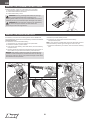
CHARGE THE VEHICLE BATTERY
CHARGING WARNINGS
WARNING: Failure to exercise caution while using this
product and comply with the following warnings could
result in product malfunction, electrical issues, excessive
heat, FIRE, and ultimately injury and property damage.
• NEVER LEAVE CHARGING BATTERIES UNATTENDED
DURING USE.
• NEVER CHARGE BATTERIES OVERNIGHT.
• The power supply must deliver power at Safety Extra Low
Voltage (SELV).
• Never attempt to charge dead, damaged or wet battery
packs.
• Never attempt to charge a battery pack containing
dierent types of batteries.
• Never allow children under 14 years of age to charge
battery packs.
• Never charge batteries in extremely hot or cold places or
place in direct sunlight.
• Never charge a battery if the cable has been pinched or
shorted.
• Never connect the charger if the power cable has been
pinched or shorted.
• Never connect the charger to an automobile 12V battery
while the vehicle is running.
• Never attempt to dismantle the charger or use a damaged
charger.
• Never attach your charger to both an AC and a DC power
source at the same time.
• Never connect the input jack (DC input) to AC power.
• Always use only rechargeable batteries designed for use
with this type of charger in the correct programming mode.
• Always inspect the battery before charging.
• Always keep the battery away from any material that could
be aected by heat.
• Always monitor the charging area and have a fire
extinguisher available at all times.Always end the charging
process if the battery becomes hot to the touch or starts
to change form (swell) during the charge process.
• Always connect the charge cable to the charger first, then
connect the battery to avoid short circuit between the
charge leads. Reverse the sequence when disconnecting.
• Always connect the positive red leads (+) and negative
black leads (–) correctly.
• Always disconnect the battery after charging, and let the
charger cool between charges.
• Always charge in a well-ventilated area.
• Always terminate all processes and contact Horizon Hobby
if the product malfunctions.
• Charge only rechargeable batteries. Charging non-
rechargeable batteries may cause the batteries to burst,
resulting in injury to persons and/or damage to property.
• The socket-outlet shall be installed near the equipment
and shall be easily accessible.
WARNING: Never leave charger unattended, exceed
maximum charge rate, charge with non-approved
batteries or charge batteries in the wrong mode. Failure to
comply may result in excessive heat, fire and serious injury.
CAUTION: Always ensure the battery you are
charging meets the specifications of this charger and
that the charger settings are correct. Not doing so can
result in excessive heat and other related product
malfunctions, which can lead to user injury or property
damage. Please contact Horizon Hobby or an authorized
retailer with compatibility questions.
1
2
3
Follow the manufacturer’s directions for your charger to
properly charge the vehicle battery.
CAUTION: Only use chargers designed to charge the
chosen battery type. Using an incorrect charger or
incorrect charger settings could cause the battery to
catch fire or explode.
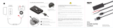
OPERATING THE INCLUDED S120 SMART CHARGER
(PRO CIRCUIT VERSION, LOS06002 ONLY)
1. Connect the S120 charger to a USB power supply
adapter.
2. Connect the Smart battery lead to the IC5 to IC3 adapter.
3. Connect the IC3 adapter to the charge port on the S120
charger.
TIP: The battery can be disconnected from the charger at
any time to stop the charging process.
4. Refer to the LED Indicator table for charger status.
5. A red LED will illuminate to indicate abnormal charging.
Follow the operation steps to ensure proper connection
is used to charge the battery.
IMPORTANT: Non-Smart batteries will cause the LED to
illuminate red and the S120 will not recognize or charge
the battery.
LED Indicator
Power On –
No Battery Connected USB 5V/1A, 5V/2A: White LED
USB Quick Charge 2.0/3.0: Blue LED
LiPo 2S and 3S
Spektrum Smart
Battery
Battery Capacity Purple LED
Less Than 25% Single Flash
25% – 75% Double Flash
76% – 99% Triple Flash
Charge Complete Green LED (Solid)
Firmware Update Red-Green-Blue Flashing LED
Error Red LED (Solid)

6
EN
INSTALL THE TRANSMITTER BATTERIES
This transmitter requires 4 AA batteries (included).
1. Remove the battery cover from the transmitter.
2. Install the batteries as shown.
3. Install the battery cover.
CAUTION: If using rechargeable batteries, charge
only rechargeable batteries. Charging non-
rechargeable batteries may cause the batteries to burst,
resulting in injury to persons and/or damage to property.
CAUTION: Risk of explosion if battery is replaced by
an incorrect type. Dispose of used batteries
according to national regulations.
1
2
3
4
5
6
7
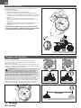
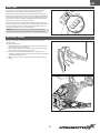
INSTALL THE VEHICLE BATTERY
The battery compartment is designed to fit the 5000mAh,
7.4V 2S 50C G2 series LiPo Smart battery with IC5 connector
(SPMX52S50H5).
To install the recommended battery:
1. Remove the pin from the battery compartment.
2. Rotate the battery hatch down.
3. Fully insert the battery, label side down, into the battery
compartment.
4. Route the battery lead wires forward through the top of
the muer as you rotate the battery hatch closed.
NOTICE: The battery lead wires must be routed over the
muer to ensure they don’t contact the rear tire during
operation. Failure to do so may cause damage to the wires
and electronic components.
5. Press up on the battery hatch.
6. Insert the pin through the hole in the battery
compartment post.
TIP: It may require considerable force the first few times to
close the battery hatch tight enough to insert the pin.
7. Insert the IC5 battery connector into the vehicle battery
port.

7
EN
00:05
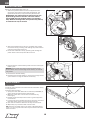
POWER ON THE VEHICLE
STEERING TEST
POWER ON THE TRANSMITTER
1. Press the power button located on
the right side of the vehicle, next
to the rider’s leg, as shown in the
illustration.
2. Place the vehicle on the included
stand and leave motionless for at
least five seconds, allowing the
vehicle to initialize.
The transmitter will emit a pair of
descending tones, and the vehicle
will emit a series of tones. When the
vehicle has initialized, the transmitter
will emit a series of tones and the
battery level indicator will display the
vehicle battery level.
When the vehicle and transmitter are
powered on, but the flywheel is o, the
transmitter emits a warning tone and
flashes the LED indicator yellow. This
is to remind you the flywheel is o.
To power on the transmitter press the power button located
on the back of the transmitter, as shown.
The transmitter will emit a tone and the battery level
indicator will briefly flash the transmitter battery level.
The LED indicator will then flash yellow.
Rotate the transmitter steering wheel left and right to test
the steering.
IMPORTANT: The front wheel of the vehicle turns the
opposite direction from the direction the transmitter
steering wheel is rotated.
If the vehicle steering operates with transmitter input, the
MS6X and ESC are both armed.

8
EN
00:30
100f (30m)
FLYWHEEL STARTUP
TRANSMITTER CONTROLS
The vehicle features a high-speed, motorized flywheel to
assist with stability.
To power on the flywheel:
1. Place the vehicle on the included stand.
2. Slide the transmitter flywheel switch to ON. The LED
indicator on the transmitter will glow solid green, and the
flywheel on the vehicle will start, gradually increasing in
speed.
3. Wait for the flywheel to reach maximum speed,
approximately 30 seconds, before attempting to drive
the vehicle.
TIP: When the flywheel has reached maximum speed,
the audible pitch of the spinning flywheel will be
constant.
IMPORTANT: Attempting to drive the vehicle without
running the flywheel or without waiting for the flywheel
to reach maximum speed is not recommended.
THROTTLE AND BRAKE
Pull the transmitter trigger to make the vehicle move
forward. The farther you pull the trigger, the faster the
vehicle will accelerate.
Push the transmitter trigger forward to apply the brake. The
vehicle is equipped with a floating disk front wheel brake and
an electronic rear wheel motor brake.
CAUTION: This vehicle is capable of very high speed.
Slowing and stopping the vehicle from full speed
requires as much as 100ft (30m). Never operate this
vehicle around people, animals or property until you are
familiar with the space requirements for safe operation.
Serious injury or property damage may result.
For the initial runs, we recommend using the transmitter
throttle limit switch to reduce the available throttle to 50 or 75
percent power. When you are comfortable with the handling
characteristics you may increase the throttle limit to 100
percent to experience the full capabilities of the vehicle.

9
EN
1 10
1 10
1 10
TURNING
The Promoto-MX uses MS6X technology to translate the
transmitter input to a desired lean angle, using the weight of
the motorcycle to produce the correct response.
Rotate the transmitter steering wheel left and right to turn
the desired direction.
• When the steering wheel is rotated right, the front wheel
turns left, shifting the weight to the right and the vehicle
leans right, then turns right.
• When the steering wheel is rotated left, the front wheel
turns right, shifting the weight to the left and the vehicle
leans left, then turns left.
IMPORTANT: The faster the vehicle moves, the more stable
it becomes, and the less responsive to steering inputs.
DRIVING
TURNING RADIUS
Similar to a full size motorcycle, the turning radius is
dependent on the speed of the vehicle. The faster the vehicle
is moving, the less responsive it is to steering input.
TIP: To make tighter turns while at speed, apply the brake
to slow down and shift weight to the front wheel, complete
your turn, and accelerate away.
STARTING
1. While holding the transmitter in your left hand, place the
vehicle on the ground and hold upright.
2. Pull the throttle trigger slightly to start the vehicle moving
forward. Once rolling, the vehicle will remain upright, as
long as you maintain a minimum speed.
IMPORTANT: The faster the vehicle moves, the more stable
it becomes, and the less responsive to steering inputs.
3. Steer using the transmitter steering wheel.
DRIVING PRACTICE
To help familiarize yourself with the handling of the vehicle,
practice turning left and right by driving in a figure-8 pattern.
Start by driving at low speed, gradually increasing your
speed as you get more comfortable.
Other maneuvers to practice:
• Making turns without allowing the lean bar wheels to
contact the ground.
• Low-speed maneuvering to become familiar with the
minimum speed at which the vehicle will remain upright.
• High-speed maneuvering
• Full speed to full-stop braking
• Turning under braking

10
EN
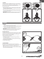
DRIVING MODES
JUMPING
The Promoto-MX has three drive modes available:
• Wheelie mode (three green LED flashes): Meant for
driving on smooth, hard pavement, this mode allows the
vehicle to pop high wheelies and balance to maintain them
while holding full throttle.
• On-road mode (two green LED flashes): Meant for
driving on smooth, hard pavement, this mode employs
wheelie suppression, which will catch wheelies early,
setting the front wheel down and allowing for maximum
acceleration.
• O-road mode (one green LED flash): Meant for driving
on dirt and grass, this mode has wheelie prevention, which
will catch most wheelies and keep the motorcycle from
flipping over under acceleration.
To change driving modes:
• Press the top of the drive mode button once to go “up” one
mode.
• Press the bottom of the drive mode button once to go
“down” one mode.
The transmitter will emit a series of tones and flash the LED
indicator a number of times corresponding to the selected
drive mode, as shown in the illustration.
If the transmitter does not emit a tone or flash the LED
indicator when pressing the button, you have reached the
end of the drive mode selections. Press the opposite side of
the drive mode button to scroll the other direction through
the drive modes.
The Promoto-MX is very capable of o-road riding and
jumping. Jumping and landing controllably requires
timing, coordination, and most importantly, practice. We
recommend starting with small jumps and progressing to
larger jumps as you become more proficient.
When jumping, always accelerate up the face of the jump.
This will pre-load the suspension and allow for a more stable,
predictable attitude through the completion of the jump.
Use the throttle to control the vehicle pitch in the air. Increasing
the throttle will cause the front wheel to pitch up. Decreasing
the throttle will cause the front wheel to pitch down.
IMPORTANT: Due to the rotational force of the flywheel,
the vehicle will pitch down more aggresively in the air than
most rc vehicles. Conversely, the vehicle pitches up much
less aggresively in the air while applying throttle than other
vehicles. Because of this, we recommend against applying
brakes in the air after leaving the jump.
The optimum landing attitude is for the rear wheel to contact
the surface first while being on the throttle, keeping the
weight from transferring to the front wheel. If you are not
on the throttle, or if the vehicle lands on the front wheel,
the weight will transfer over the front wheel, causing a less
controllable landing.

11
EN
RUN TIME
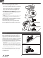
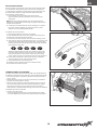
MX START STAND
Run time for the vehicle is approximately 9-12 minutes,
depending on your throttle usage and driving style.
The vehicle battery capacity is represented by the Smart
battery level indicator on the transmitter. When the battery
level drops below normal, a single green LED flashes on the
battery level indicator. When the single green LED flashes,
recharge or replace the vehicle battery.
If you continue to drive beyond the battery alarm, the low
voltage cuto (LVC) will activate, cutting power to the motor.
LVC is a function built into the electronic speed control to
protect the battery from over-discharge.
NOTICE: Repeated driving to the low voltage cuto will
damage the vehicle battery and shorten the battery life.
The Promoto-MX includes a motocross stand to use for
racing starts.
To use the MX stand:
1. Place the stand on flat solid ground as shown, with the
side supports fully extended.
2. Insert a 5in. 40D nail (included) through the hole in the
end of each wing and into the ground.
3. Insert the rear wheel of the vehicle in the stand as
shown, pressing the wheel fully into the stand. The stand
will hold the wheel firmly.
4. When ready to start, simply press the throttle to drive
away.

12
EN
1
2
3
4
00:30
MAINTENANCE
DRIVE CHAIN
The drive chain should be cleaned and lubricated after every
running session.
To clean the drive chain:
1. Spray the chain with Nitro RC Car Cleaner (DYN5505) or
other plastic and electronics-safe cleaner.
2. Wipe the chain with a clean cloth and allow to dry
thoroughly.
3. Repeat the above steps until no dirt or grease appears
on the cloth.
4. Lightly apply the included chain oil to the roller portion of
the chain links, working around the entire chain.
5. Spin the rear wheel to work the oil fully into the chain.
6. Wipe away any excess oil with a clean cloth.
TIP: After the included chain oil is spent, LOS77002 Chain
Lube or a “dry” bicycle chain lube may be used to lubricate
the drive chain.
AFTER YOUR RUN
When you are finished with your run:
1. Slide the flywheel switch to OFF. The flywheel has a
electronic drag brake to help slow the flywheel. The
flywheel should stop in approximately 30 seconds.
IMPORTANT: The vehicle must be powered on for the
flywheel drag brake to function. Leave the vehicle
powered ON until the flywheel comes to a complete
stop. Without the drag brake, the flywheel may take up
to 5 minutes to stop on its own.
2. After the flywheel has come to a complete stop, power
the vehicle o by pressing and holding the power button
until the orange LED turns o.
3. Power the transmitter o by pressing and holding the
power button until the power LED turns o.
4. Disconnect the vehicle battery lead from the motorcycle
battery port.
NOTICE: Never leave the battery lead connected to the
vehicle when not in use. Damage to the battery or vehicle
may result.
5. Remove the vehicle battery.
6. Recharge the vehicle battery or charge to storage level if
you are done running the vehicle for the day.

13
EN
DRIVE CHAIN TENSION
As the vehicle is driven more, the drive chain will seat with
the sprockets and possibly wear some. As this happens,
it may become necessary to adjust the chain tension. The
Promoto-MX includes a chain tension adjustment set.
To check the chain tension:
1. Press down on the top side of the drive chain,
approximately half way between the front and rear
sprockets.
TIP: When correctly tensioned, the chain should be as
taught as possible without causing any tight spots as the
rear wheel is rotated.
2. If the chain contacts the top of the trailing arm, adjust
the chain tension tighter by changing the rear axle
spacer pill +.25, as described below.
To adjust the chain tension:
1. Remove the M4 nut from the rear wheel.
2. Pull the M4 axle out of the rear wheel and trailing arm.
3. Move the rear wheel out of the way.
4. Press the rear axle spacer pills out of the trailing arms.
5. The spacers pills are marked with a zero or a number and
arrow to show the distance and direction from the zero
position the spacer will move the axle. The pills installed
at the factory may vary.
Always install the spacer pills as a matching set, with
the hole toward the rear of the trailing arm. Select the
appropriate spacers and insert them into the trailing
arms, ensuring they are oriented in the correct direction.
6. Install the rear wheel, ensuring the chain is installed
around both the front and rear sprockets.
7. Install the M4 rear axle and M4 nut.
8. Rotate the rear wheel to ensure it rotates freely.
9. Re-check the chain tension.
LEAN BAR WHEEL ADJUSTMENT
The lean bar wheels on the Promoto-MX may be adjusted up
and down to suit the terrain and your driving experience level.
• The stock position is good for general running o-road in
dirt or grass.
• Raise the lean bars for running on pavement, to allow for
greater lean and tighter turning.
• Lower the lean bars for less experienced drivers running
o-road. Having the lean bars lowered allows for easier
starting from a stop, as the motorcycle will “stand up”
when power is applied while leaning on the lean bar wheels.
To adjust the lean bar wheels:
• Using a 2mm hex driver
- turn the adjustment screw in to raise the lean bar wheel.
- turn the adjustment screw out to lower the lean bar wheel.

14
EN
LIMITED WARRANTY
What this Warranty Covers
Horizon Hobby, LLC, (Horizon) warrants to the original
purchaser that the product purchased (the “Product”) will be
free from defects in materials and workmanship for a period
of 2 years from the date of purchase.
What is Not Covered
This warranty is not transferable and does not cover (i)
cosmetic damage, (ii) damage due to acts of God, accident,
misuse, abuse, negligence, commercial use, or due to
improper use, installation, operation or maintenance, (iii)
modification of or to any part of the Product, (iv) attempted
service by anyone other than a Horizon Hobby authorized
service center, (v) Product not purchased from an authorized
Horizon dealer, or (vi) Product not compliant with applicable
technical regulations or (vii) use that violates any applicable
laws, rules, or regulations.
OTHER THAN THE EXPRESS WARRANTY ABOVE, HORIZON
MAKES NO OTHER WARRANTY OR REPRESENTATION, AND
HEREBY DISCLAIMS ANY AND ALL IMPLIED WARRANTIES,
INCLUDING, WITHOUT LIMITATION, THE IMPLIED
WARRANTIES OF NON-INFRINGEMENT, MERCHANTABILITY
AND FITNESS FOR A PARTICULAR PURPOSE. THE
PURCHASER ACKNOWLEDGES THAT THEY ALONE HAVE
DETERMINED THAT THE PRODUCT WILL SUITABLY MEET
THE REQUIREMENTS OF THE PURCHASER’S INTENDED USE.
Purchaser’s Remedy
Horizon’s sole obligation and purchaser’s sole and exclusive
remedy shall be that Horizon will, at its option, either (i)
service, or (ii) replace, any Product determined by Horizon
to be defective. Horizon reserves the right to inspect any
and all Product(s) involved in a warranty claim. Service or
replacement decisions are at the sole discretion of Horizon.
Proof of purchase is required for all warranty claims.
SERVICE OR REPLACEMENT AS PROVIDED UNDER THIS
WARRANTY IS THE PURCHASER’S SOLE AND EXCLUSIVE
REMEDY.
Limitation of Liability
HORIZON SHALL NOT BE LIABLE FOR SPECIAL, INDIRECT,
INCIDENTAL OR CONSEQUENTIAL DAMAGES, LOSS OF
PROFITS OR PRODUCTION OR COMMERCIAL LOSS IN ANY
WAY, REGARDLESS OF WHETHER SUCH CLAIM IS BASED
IN CONTRACT, WARRANTY, TORT, NEGLIGENCE, STRICT
LIABILITY OR ANY OTHER THEORY OF LIABILITY, EVEN IF
HORIZON HAS BEEN ADVISED OF THE POSSIBILITY OF SUCH
DAMAGES. Further, in no event shall the liability of Horizon
exceed the individual price of the Product on which liability
is asserted. As Horizon has no control over use, setup,
final assembly, modification or misuse, no liability shall be
assumed nor accepted for any resulting damage or injury.
By the act of use, setup or assembly, the user accepts all
resulting liability. If you as the purchaser or user are not
prepared to accept the liability associated with the use of
the Product, purchaser is advised to return the Product
immediately in new and unused condition to the place of
purchase.
Law
These terms are governed by Illinois law (without regard to
conflict of law principals). This warranty gives you specific
legal rights, and you may also have other rights which vary
from state to state. Horizon reserves the right to change or
modify this warranty at any time without notice.
WARRANTY SERVICES
Questions, Assistance, and Services
Your local hobby store and/or place of purchase cannot
provide warranty support or service. Once assembly, setup
or use of the Product has been started, you must contact
your local distributor or Horizon directly. This will enable
Horizon to better answer your questions and service you in
the event that you may need any assistance. For questions
or assistance, please visit our website at www.horizonhobby.
com, submit a Product Support Inquiry, or call the toll free
telephone number referenced in the Warranty and Service
Contact Information section to speak with a Product Support
representative.
Inspection or Services
If this Product needs to be inspected or serviced and is
compliant in the country you live and use the Product in,
please use the Horizon Online Service Request submission
process found on our website or call Horizon to obtain a
Return Merchandise Authorization (RMA) number. Pack
the Product securely using a shipping carton. Please note
that original boxes may be included, but are not designed
to withstand the rigors of shipping without additional
protection. Ship via a carrier that provides tracking and
insurance for lost or damaged parcels, as Horizon is not
responsible for merchandise until it arrives and is accepted
at our facility. An Online Service Request is available at
http://www.horizonhobby.com/content/service-center_
render-service-center. If you do not have internet access,
please contact Horizon Product Support to obtain a RMA
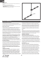
12Nm
FORK TOOLS
Use the fork tools to grip the flats on the fork sections as
shown.
• The tube requires the 9mm end.
• The end fitting requires the 6mm end.
IMPORTANT: When re-assembling the fork tube, the end
fitting should be tightened to 12Nm.

15
EN
WARRANTY AND SERVICE CONTACT INFORMATION
COUNTRY
OF PURCHASE HORIZON HOBBY CONTACT INFORMATION ADDRESS
United States of
America
Horizon Service Center
(Repairs and Repair Requests) servicecenter.horizonhobby.com/RequestForm/
2904 Research Rd.
Champaign, Illinois 61822
USA
Horizon Product Support
(Product Technical
Assistance)
productsupport@horizonhobby.com
877-504-0233
Sales websales@horizonhobby.com
800-338-4639
European Union
Horizon Technischer Service service@horizonhobby.eu
+49 (0) 4121 2655 100
Hanskampring 9
D 22885 Barsbüttel,
Germany
Sales: Horizon Hobby GmbH
number along with instructions for submitting your product
for service. When calling Horizon, you will be asked to
provide your complete name, street address, email address
and phone number where you can be reached during
business hours. When sending product into Horizon, please
include your RMA number, a list of the included items, and a
brief summary of the problem. A copy of your original sales
receipt must be included for warranty consideration. Be sure
your name, address, and RMA number are clearly written on
the outside of the shipping carton.
NOTICE: Do not ship Li-Po batteries to Horizon. If you
have any issue with a Li-Po battery, please contact the
appropriate Horizon Product Support oce.
Warranty Requirements
For Warranty consideration, you must include your original
sales receipt verifying the proof-of-purchase date. Provided
warranty conditions have been met, your Product will be
serviced or replaced free of charge. Service or replacement
decisions are at the sole discretion of Horizon.
Non-Warranty Service
Should your service not be covered by warranty, service
will be completed and payment will be required without
notification or estimate of the expense unless the expense
exceeds 50% of the retail purchase cost. By submitting
the item for service you are agreeing to payment of the
service without notification. Service estimates are available
upon request. You must include this request with your item
submitted for service. Non-warranty service estimates will
be billed a minimum of 1/2 hour of labor. In addition you will
be billed for return freight. Horizon accepts money orders
and cashier’s checks, as well as Visa, MasterCard, American
Express, and Discover cards. By submitting any item to
Horizon for service, you are agreeing to Horizon’s Terms and
Conditions found on our website http://www.horizonhobby.
com/content/service-center_render-service-center.
ATTENTION: Horizon service is limited to Product
compliant in the country of use and ownership. If received,
a non-compliant Product will not be serviced. Further, the
sender will be responsible for arranging return shipment
of the un-serviced Product, through a carrier of the
sender’s choice and at the sender’s expense. Horizon will
hold non-compliant Product for a period of 60 days from
notification, after which it will be discarded.
10/15

16
EN
COMPLIANCE INFORMATION FOR THE EUROPEAN UNION
EU COMPLIANCE STATEMENT:
LOSI Promoto-MX RTR (LOS06000); Hereby,
Horizon Hobby, LLC declares that the device is in
compliance with the following: Radio Equipment Directive
(RED) 2014/53/EU; RoHS 2 Directive 2011/65/EU; RoHS 3
Directive - Amending 2011/65/EU Annex II 2015/863.
LOSI Promoto-MX Pro Circuit RTR (LOS06002);
Hereby, Horizon Hobby, LLC declares that the device is in
compliance with the following: Radio Equipment Directive
(RED) 2014/53/EU; Low Voltage Directive (LVD) 2014/35/
EU; 2014/30/EU EMC Directive; RoHS 2 Directive 2011/65/
EU; RoHS 3 Directive - Amending 2011/65/EU Annex II
2015/863.
The full text of the EU declaration of conformity is available
at the following internet address: https://www.horizonhobby.
com/content/support-render-compliance.
NOTE: This product contains batteries that are covered
under the 2006/66/EC European Directive, which cannot
be disposed of with normal household waste. Please follow
local regulations.
Wireless Frequency Range and Wireless Output Power:
Transmitter:
2402 – 2478 MHz
17.7dBm
Receiver:
2405 – 2478 MHz
5.779dBm
EU Manufacturer of Record:
Horizon Hobby, LLC
2904 Research Road
Champaign, IL 61822 USA
EU Importer of Record:
Horizon Hobby, GmbH
Hanskampring 9
22885 Barsbüttel Germany
WEEE NOTICE:
This appliance is labeled in accordance with
European Directive 2012/19/EU concerning waste
of electrical and electronic equipment (WEEE). This
label indicates that this product should not be
disposed of with household waste. It should be
deposited at an appropriate facility to enable recovery and
recycling.
FCC INFORMATION
IC INFORMATION
Contains FCC ID: BRWKATY1T
FCC ID: BRWSPMSR6300PM
This equipment complies with FCC and IC radiation exposure
limits set forth for an uncontrolled environment. This
equipment should be installed and operated with minimum
distance 20cm between the radiator and/or antenna and
your body (excluding fingers, hands, wrists, ankles and feet).
This transmitter must not be co-located or operating in
conjunction with any other antenna or transmitter.
SUPPLIER’S DECLARATION OF CONFORMITY
LOSI Promoto-MX RTR (LOS06000, LOS06002)
This device complies with part 15 of the FCC Rules.
Operation is subject to the following two conditions:
(1) This device may not cause harmful interference,
and (2) this device must accept any interference received,
including interference that may cause undesired operation.
CAUTION: Changes or modifications not expressly
approved by the party responsible for compliance
could void the user’s authority to operate the equipment.
NOTE: This equipment has been tested and found
to comply with the limits for a Class B digital device,
pursuant to part 15 of the FCC Rules. These limits are
designed to provide reasonable protection against harmful
interference in a residential installation. This equipment
generates, uses and can radiate radio frequency energy
and, if not installed and used in accordance with the
instructions, may cause harmful interference to radio
communications. However, there is no guarantee that
interference will not occur in a particular installation. If this
equipment does cause harmful interference to radio or
television reception, which can be determined by turning
the equipment o and on, the user is encouraged to try to
correct the interference by one or more of the following
measures:
• Reorient or relocate the receiving antenna.
• Increase the separation between the equipment and
receiver.
• Connect the equipment into an outlet on a circuit dierent
from that to which the receiver is connected.
• Consult the dealer or an experienced radio/TV technician
for help.
Horizon Hobby, LLC
2904 Research Road Champaign, IL 61822
Email: compliance@horizonhobby.com
Web: HorizonHobby.com
CAN ICES-3 (B)/NMB-3(B)
CONTAINS IC: 6157A-KATY1T
IC: 6157A-SPMSR6300PM
This device contains license-exempt transmitter(s)/
receivers(s) that comply with Innovation, Science, and
Economic Development Canada’s license-exempt RSS(s).
Operation is subject to the following 2 conditions:
1. This device may not cause interference.
2. This device must accept any interference, including
interference that may cause undesired operation of the
device.

59
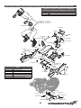
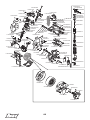
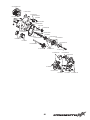
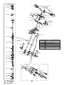
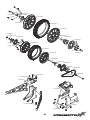
EXPLODED VIEWS | EXPLOSIONSZEICHNUNGEN | VUES ÉCLATÉES | VISTE ESPLOSE
LOS260007 - FXR Red
LOS260012 - ClubMX FXR
LOS260013 - Pro Circuit
LOS261006
LOS261006
TLR5962
TLR5964
TLR5904
TLR233043
LOS261008
LOS261008
TLR5904
LOS261004
LOS261003
TLR255013
LOS*
LOS*
LOS*
TLR5909
TLR255013
LOS255018
LOS255018
TLR5962
LOS261003
LOS266000
LOS261003
TLR5961
LOS264003
TLR255010
LOS264002 TLR255007 LOS264002
LOS255018
LOS264003
LOS264002
TLR5903
TLR5961
JERSEYS (not shown) | JERSEYS (nicht abgebildet)
CHANDAILS (non illustrés) | MAGLIE (non mostrato)
LOS260008 FXR
LOS260009 ClubMX
LOS260010 Pro Circuit
LOS*
LOS260000 Red, Rot, Rouge, Rosso
LOS260001 Blue, Blau, Bleu, Blu
LOS260002 Green, Grün, Vert, Verde
LOS260003 Yellow, Gelb, Jaune, Giallo
LOS260004 Orange, Orange, Orange, Arancione
LOS260005 White, Weiß, Blanc, Bianco
LOS260006 Black, Schwarz, Noir, Nero

60
LOS261009
TLR245016
LOS261010
LOS261002
LOS261002
LOS262004
TLR5930
LOS235005
TLR5963
LOS255016
TLR255006
SPMXMXE85
LOS261010
LOS261010
LOS261009
LOS261009
TLR235003
LOS261012
SPMS620PM
TLR5903
LOS261013
LOS261013
LOS261006
LOS255016
LOS255016
LOS261014
TLR235006
LOS261011
LOS267000
LOS262005
LOS262005
LOS262005
LOS262008
LOS264000
TLR5903
LOS264000
LOS264000
TLR235006
LOS262002
LOS262002
LOSA6940
TLR5961
TLR5902
LOS255017
TLR255013
LOSA6945
LOSA6945
LOSA6940
LOS262008
TLR235005
TLR245014
LOS255014
TLR5902
LOS264001
LOS264001
LOS235024
LOS264001
LOS264005
SPMSR6300PM
LOS264003
LOS264002 LOS255007
LOS264005
LOS267001
LOS267001
LOS264005
LOS255014
LOS255014
TLR6352
SPMSSX108PM
LOS263011
LOS263009
LOS263010
LOS263009
LOS263009
LOS263008
LOS263008
LOS263001
LOS263008
TLR255002
LOS263008
TLR233043
LOS263012
LOS235024
LOS263012
LOS261005
SPMXMXA2
SPMXMXA1
SPMXMXA1
TLR5901
LOS261005
TLR5904

61
LOS261013
TLR5903
LOS262008
LOS262008
LOS262008
LOS262006
LOS262006
TLR232080
TLR6932
TLR6932
LOS262007TLR256005
LOS262005
LOS262006
SPMXSM3200
TLR5961 TLR5961
LOS255017
LOS261002
TLR255013
TLR5963
TLR5930
LOS262016
TLR6352
LOS245017
LOS255016
LOS261006
TLR5962 TLR5930 LOS255016
TLR5962
LOS261014
LOS235005

62
LOS*
TLR5963
TLR5904
TLR5963
TLR5904
LOS261007
LOS*
TLR255007
LOS262011
LOS264004
LOS264004
LOS264004
LOS267003
LOS265001
LOS265001
LOS265001
LOS265001
TLR5904
TLR5910
TLR231078
LOS*
LOS*
TLR5903
TLR6313
TLR255007
TLR235014
LOS264006
TLR5904
TLR5903
TLR5904
LOS262009
LOS262009
TLR5904
TLR6312
TLR6312
LOS263004
LOS263004
LOS263003
LOS263003
LOS263005
LOS263006
LOS263003
LOS263006
LOS263000
LOS263000
LOS263003
LOS263003
LOS263003
LOS263003
LOS263006
LOS263004
LOS*
LOS260000 Red, Rot, Rouge, Rosso
LOS260001 Blue, Blau, Bleu, Blu
LOS260002 Green, Grün, Vert, Verde
LOS260003 Yellow, Gelb, Jaune, Giallo
LOS260004 Orange, Orange, Orange, Arancione
LOS260005 White, Weiß, Blanc, Bianco
LOS260006 Black, Schwarz, Noir, Nero
La page est en cours de chargement...
La page est en cours de chargement...
La page est en cours de chargement...
La page est en cours de chargement...
La page est en cours de chargement...
La page est en cours de chargement...
La page est en cours de chargement...
La page est en cours de chargement...
La page est en cours de chargement...
-
 1
1
-
 2
2
-
 3
3
-
 4
4
-
 5
5
-
 6
6
-
 7
7
-
 8
8
-
 9
9
-
 10
10
-
 11
11
-
 12
12
-
 13
13
-
 14
14
-
 15
15
-
 16
16
-
 17
17
-
 18
18
-
 19
19
-
 20
20
-
 21
21
-
 22
22
-
 23
23
-
 24
24
-
 25
25
-
 26
26
-
 27
27
-
 28
28
-
 29
29


Losi LOS06000T1 Manuel utilisateur
- Catégorie
- Jouets télécommandés
- Taper
- Manuel utilisateur
- Ce manuel convient également à
dans d''autres langues
- English: Losi LOS06000T1 User manual
Documents connexes
Autres documents
-
Axial AXI03005T2 Le manuel du propriétaire
-
Arrma ARA5810 Le manuel du propriétaire
-
Arrma ARA110002T1 Le manuel du propriétaire
-
-
ULTIMATE SPEED Car and Motorcycle Battery Charger Manuel utilisateur
-
 SP CONNECT MAN115 Manuel utilisateur
-
HOMCOM 835-205V80 Mode d'emploi
