
تﺎﻤﯿﻠﻌﺘﻟا ﻞﯿﻟدماﺪﺨﺘﺳﻻ ﺔﻨﺧﺪﻤﻟا
INSTRUCTION MANUAL FOR CHIMNEY HOODS
HOTTE GUIDE D’UTILISATION

1
EN
SCOPE OF INSTRUCTION MANUΑL
Dear Customer,
In the sections provided herein, there is necessary information which will enable you to use the
device efficiently and safely. Please, read these instructions carefully before installation of the
device
Section 1 Important points which must be observed before using the chimney
Section 2 Technical specifications of the chimney hood.
Section 3 Technical dimensions of the chimney hood
Section 4 Electrical diagram of the chimney hood.
Section 5 Information about installation connection of the chimney hood.
Section 6 Information about use of the chimney hood.
Section 7 Information about maintenance of the chimney hood.
THE DEVICE IS PRODUCED AS EARTHED.
DO NOT USE IT WITH UNEARTHED PLUG.
IMPORTANT PRECAUTIONS AND POINTS WHICH MUST BE OBSERVED
Section 1
1. The electrical and installation connections must be done by the service staff who is well-
informed of the subject;
2. The operating voltage is 220 – 240 Volts. Do not operate the device in lower or higher
voltage.
3. Do not connect to the chimneys where the heating stove is connected, to the gas flue or to
the chimneys where the fire rises.
4. Plug the product into the socket where there is an earthed connection.
5. Fire catching food should not be cooked under the device.
6. Do not use other materials instead of aluminum filter in the device.
7. Do not plug into the socket without completion of the installation of the device.
8. Do not run the device without aluminum filter.
9. Do not touch the bulb of the device when it is left on for a long time..

2
EN
10. Do not remove the aluminum filter when the device is running.
11. Do not turn off the device directly by plugging it out when it is running. Turn it off from
control panel.
12. The device should be cleaned periodically..
13. The height between the lower surface of the chimney hood and oven must be 65 cm for
electrical ovens, and 75 cm for gas-fired or mix ovens
14. Keep the packaging material away from the children because they may be dangerous for
them.
15. Run the chimney hood after the kettle or frying pan is put on the oven.
16. Run the chimney hood for 15 minutes more after the operation of cooking or frying is
finished in order to clean the air of the kitchen off the smell and vapor which appeared
during cooking..
17. Let some fresh air into environment when the chimney hood is running, especially, when it
is used in the same time with the gas-fired ovens.
18. Contact the nearest service if your device is failed to run with any reason.
19. Our Company may not be held responsible from the failures arising from use which is not
consistent with the cautions stated above.
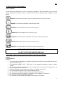
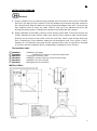
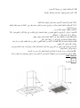
TECHNICAL SPECIFICATIONS
Section 2
1. Chimney
2. Control panel
3. Body of the chimney hood
4. Aluminum filter
5. Illumination lamp
6. Glass

3
EN
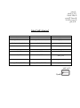
TECHNICA L SPECIFICA TIONS OF THE CHIMNEY HOOD
LENGTH 600-900 mm
WIDTH 475 mm
HEIGHT Min. 706 mm Max 980
mm
CONTROLLER PUSH BUTTON
AIR SUCTION 336,2 m3/h
BULB POWER 1x2 W
MOTOR POWER 1 1 0 W
TOTAL P OWER 112 W
DIAMETER OF AIR OUTLET
PIPE
120 mm
SUPPLY VOLTAGE 220 – 240 V 50Hz
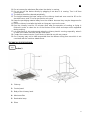
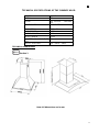
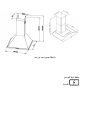
T ECHNICA L DIMENSIONS
Section 3
Note: All dimensions a re in mm.

4
EN
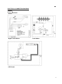
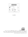
ELECTRICAL CONNECTION DIAGRAM
Section 4
Digital Touch Button Push Button
LCD Screen

5
EN
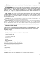
INSTALLATION DIAGRAM
Section 5
1. Draw a straight line by a measuring stick starting from the surface of the oven to 700+280:
990 mm if you want to save a space of 700 mm between the oven and the lower surface of
the chimney hood. Align the drawn line to the right and left edges. Draw a 67,5 mm axis line
from aligned center to every two sides. Make a hole by 6 mm diameter electrical drill
through two drawn points. Penetrate the expansion bolt and install the hangers.
2. Doing installation of secondary chimney of the chimney hood: draw 75 mm line from the top
surface towards the lower section. Make sure that the line is equal to right and left parts.
Draw 50 mm line each at both sides of the line and, then, make a hole through these two
lines. Penetrate an 8 mm diameter expansion bolt and tighten until 2 mm space is left in-
between of a 2,5 diameter slat screw and the expansion bolt. Later, the product is mounted
on its place and the installation will be completed by installing the inner chimney.
The operation order:
1
st
operation: Installation of hanger
2
nd
operation: Installation of chimney connection metal sheet
3
rd
operation: Hanging the chimney hood
4
th
operation: Installation of lower chimney of the chimney hood
5
th
operation: Installation of inner chimney
6
th
operation: Making electrical connection
INSTALLATION :

6
EN
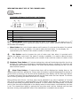
INFORMATION ABOUT USE OF THE CHIMNEY HOOD
Section 6-1
LCD-Switch Chimney Hood Control Card Features
A
ON-OFF BUTTON
B
MINUS BUTTON
C
PLUS BUTTON
D
TIMER BUTTON
E
BULB BUTTON
F
ALARM BUTTON
On/Off Button: used to start and stop the motor. In the beginning, the motor runs in 2
nd
cycle. The number of cycle is represented by bar levels and the rotation speed of the fan shown at
the left-side of the display.
Minus Button: the cycle of motor reduces until it reaches 1
st
cycle each time when it is pushed
if the motor is running. In addition, it is used to reduce the timer value. On the display, it is
represented by the number of bars and the number of rotation of the fan.
Plus Button: used to increase the cycle of motor each time when it is pushed until it
reaches the highest cycle level if the motor is running. In addition, it is used to reduce the timer
value. On the display, it is represented by the number of bars and the number of rotation of the
fan.
Shutdown Timer Button: a 15 minute starting timer value will be displayed and the clock icon
will flash for 5 times when this button is pushed while the motor is running. The clock icon will
be displayed until the timer value lapses. The motor will stop and the bulb will turn off, if it is on,
when the timer lapsed.
Alarm Timer Button: a 5 minute alarm timer will be displayed as starting timer on the
display and the bell icon will flash for 5 times when this button is pushed independent of whether or
not the motor is running. The bell icon will be displayed on the display until the timer time lapses.
The buzzer will ring for 20 seconds and the bell icon will flash when the timer lapsed. The buzzer
can be shut by pushing the alarm timer when it is ringing.
Being valid for both of them; the timer value can be adjusted to any value in-between of 1 minute
and 9 hour 59 minutes by pushing MINUS or PLUS buttons while flashing. The timer value will
increase or decrease very quickly when the MINUS or PLUS buttons are held pushed. The current
value of the timer will be displayed on the display when the timer button is pushed while the timer
is set. The started timer button is pushed one more time and it will be reduced until the timer
becomes zero by pushing MINUS button if the started timer is needed to be cancelled.

7
EN
Bulb Button: used to turn on and off the bulb. The bulb will appear at the right-side of the
display while it is on.
Boost Adjusting: pressing the PLUS button one more time while the motor is running with the
highest cycle will let to enter into a boost mode. In the boost mode, the motor will pass to a next
lower cycle in every 3 minute lapse and will rotate in 2
nd
cycle continuously by getting out from
boost mode. The TURBO icon will flash on the display while in boost mode. The boost mode will
be exited if the cycle of the motor is changed.
Filter Warning: the (CLEAN FILTER) message which expresses that the filter should be
cleaned will appear on the display when the motor runs for 60 hours. The beep sound will be heard
and the (CLEAN FILTER) message will appear for 1,5 seconds more when the M.on/off button is
held pressed for 4 seconds.
Power On: the clock which is valid when the power failure occurred will be brought on the
power on, and the operation will continue in clock adjusting mode.
Adjusting the Clock: pressing the MINUS and the PLUS button in the same moment will let to
enter into a clock adjusting mode. During clock adjustment, a triangular icon in the right midst of
the clock will flash on the display. The clock is adjusted by MINUS and PLUS buttons. The clock
adjusting mode will be exited if any other button is pushed other than MINUS and PLUS buttons.
Returning to Factory Settings
A beep sound will be heard and the (Fac) message will appear on the display when the M. on/off,
MINUS and PLUS buttons are kept pushed for 4 seconds in the same moment, and the factory
settings are returned.
The Factory Settings
RGB Display Lightening Color: Red-100, Green-100, Blue-100
Display Lightening: ON
Click (the key sound): ON
Bulb Option: ON
Section 6-2
PUSH BUTTON SWITCH USING INFORMATION
The functions of the buttons are as follows:
0. Off
1. Mild ventilation
2. Medium ventilation
3. Strong ventilation
Note: While cooking food, push the buttons 1 or 2. For frying or similar meals, use 3.

8
EN
0 : Stop the engine
1 : Powering the first level
2 : Powering the second level
3 : Powering the third level
: On and off button of lamp
Section 6-3
INFORMATION ABOUT USE OF TOUCH-OPERATED SWITCH
A
ON – OFF BUTTON
B
MINUS BUTTON
C
DIGITAL DISPLAY
D
PLUS BUTTON
E
TIMER BUTTON
F
BULB BUTTON
A – On/Off Button: used to start and stop the motor. The motor starts running in 2
nd
cycle
when On-Off button is pushed for the first time.
B – Minus Button: reduces the cycle of the motor.
C – Digital Display: shows in which cycle the motor is.
D – Plus Button: used to increase the cycle of the motor with one level.
E – Timer Button: when this button is pushed, the cycle of the motor flashes on digital display
and the motor stops within 15 minutes. It is necessary to keep pushed this button for 3 seconds
to activate it. Push only one time to cancel it.
F – Bulb Button: used to turn on and off the bulb.

9
EN
INFORMATION ABOUT MAINTENANCE
Section 7-1
Plug out the product, or turn off the power switch, or loosen or turn off the safety fuse supplying the
chimney hood, before starting maintenance operation.
Aluminum Filter
This filter is used to catch the oil particles in the air and, thus, it will be blocked after a period of
time which will change depending on the frequency of use of the device. We recommend that this
filter is cleaned once a month at most to make sure that the device does not pose a danger. For
this operation, firstly, remove the aluminum filter. Wash the filters with liquid washing agent and
flush, and mount it on its place after drying. The change in color may be observed as the aluminum
filters are washed. This is normal and there is no need to replace the filters. It is also possible to
wash the aluminum filter in the dishwashing machine.
Removing Aluminum Filter
1. Push the lock of the aluminum filter forward.
2. Then, slightly lower it downwards and push forward. Otherwise, the filter can be defected.
Wash the aluminum filter and mount it again into its place by applying the steps mentioned
above in reverse.
Carbon filter (it is for flueless use)
This filter removes the cooking smell. It cleans the circulating air within the kitchen in case there is
no possibility to use chimney. Physical life of the carbon filter of the device will expire depending on
the frequency of use and mode of cooking, and that of aluminum filter will expire depending on the
cleaning regularly.
In usual use, it should be replaced once in every 4 months at most.
Removing Carbon Filter:
1. Remove the aluminum filter.
2. To remove the carbon filter, turn it to the left and pull it towards yourself.
3. Mount a new carbon filter.
4. Mount the aluminum filters.

10
EN
Section 7-2
Use soft cloth wetted with water to clean the exterior surface of the chimney hood. Never use
abrasive and scratching products for cleaning. The cloth must be applied in the same direction with
the brush in order to avoid scratching of the steel drum. The bulb glasses must not be removed
during cleaning.
CAUTION!
You may cause fire if you do not observe the rules pertaining to cleaning and replacing the filters of
the chimney hood.
Replacing the Bulb
There are 2 pieces of 25 W halogen bulbs on the chimney hood. First of all, plug out the product,
or turn off the power switch, or loosen or turn off the safety fuse supplying the chimney hood to
replace the bulb. Slightly press on the connecting tabs existing on the cover of the halogen bulb
with a thin tip screwdriver and push them downward. Hold the cover carefully not to let it drop down
when performing this operation. Slightly push the cover by aligning the tabs to the cavities on bulb
hole after the bulb is replaced. It is recommended that the new bulb is fixed with cloth. It is because
of fact that the life of the bulb will expire in 1 day when the halogen bulbs are touched with bare
hand.
CAUTION!
Touch the bulb only when you will replace it. The life of bulb will expire after one day when the
halogen bulb is touched when it is not broken.
Firstly, disconnect the electricity of the chimney hood and dismantle it if you need it to be
transported. Carry it in its original box, if possible, and observe the transportation signs put on the
box. If no original box, make sure that the product is packed so that it would protect from any
damage.
We kindly ask you to observe following recommendations:
1. Make sure that the Warranty Certificate is endorsed by the Authorized Seller when the
product is received.
2. Use the product in accordance with the principles provided in the instructions for use.
3. Ask for the “technician identity card” from the technician who came for the technical service.

11
FR
Chers Utilisateurs,
Nous vous remercions pour votre choix de produit. Afin de pouvoir utiliser votre hotte en sécurité et
de manière efficace pour une longue durée, le bon montage de ce dernier est indispensable, nous
vous conseillons de lire attentivement le mode d’emploi avant son utilisation.
1) PROCEDURE A SUIVRE AVANT L’UTILISATION
1. Brancher votre hotte sur une prise de terre 220 V « LE FOURNISSERUR NE SERA EN AUCUN
CAS RESPONSABLE SI DES DEFAILLANCES SE PRESENTES EN RAISON D’UNE
MAUVAISE UTILISATION »
2. Prévoyez la sortie de la hotte au tuyau de cheminée, comme pour la connexion de la chaudière, et
le chauffe-eau.
3. Assurez vous que les boutons sur le panneau de la hotte soit en position fermée avant le
branchement de ce dernier.
4. Placer l’ampoule en ouvrant le boitier à filtre en aluminium placé sous la hotte
5. Effectuer le montage de votre hotte à l’aide du schéma fournit dans l’emballage.
6. La distance préconisée entre la plaque à trou (filtre) de votre hotte et de votre gazinière doit être
au minimum 75 cm et 65 cm pour les fours électriques.
7. Votre hotte a été conçue de manière à l’utiliser avec ou sans connexion de tuyau pour cheminée.
1) UTILISATION AVEC TUYAU DE CHEMINEE
Sur votre hotte se trouve une sortie d’air. Les trous de sortie d’air sont de 12 cm de diamètre et sont
connectés au tuyau de cheminée à l’aide d’un tuyau en aluminium. Les précautions doivent être
prises pour les tuyaux verticaux afin d’éviter l’entrée d’eau de pluie. Dans le cas d’une défaillance
due à cette raison, la garantie de votre hotte ne sera pas valable. A cet égard, il est recommandé
d’utiliser un tuyau d’un diamètre de 120mm. Plus votre tuyau sera court et sans angle, plus votre
hotte sera efficace.
2) UTILISATION SANS TUYAU DE CHEMINEE
Important: Si toutefois l’utilisation se fait sans tuyau de cheminée vous pouvez vous procurer un
filtre en carbone auprès de nos services compétents.
Vous pouvez remplacer le filtre par le FİLTRE EN CARBONE délivré par le service en retirant le
boitier à filtre en appuyant sur les poignées. Votre hotte est donc prête à fonctionner.

12
FR
4) MONTAGE DE LA HOTTE
Afin de servir d’exemple, vous pouvez marquer d’un point les points de fixation avant ou arrière et
les points de fixation du tuyau de cheminée à l’ endroit où vous souhaitez monter votre hotte.
Figure 1: Vider la sortie du tuyau de cheminée. Pour la connexion supérieure utiliser 4 vis 3,5x16
YHB pour le montage de la hotte sur le placard de cuisine.
Enfoncer les 2 chevilles de 8 mm fournis au mur en forant à l’aide d’une perceuse 2 trous de
diamètre 7.8mm et de profondeur 45 mm.
Visser les éléments de montage (forme L) dans les trous en assurant un espace de 10 mm.
Figure 2: Monter la hotte de haut en bas par son placement de montage se trouvant derrière, et la
fixer en vissant les vis en forme de L.
Assurez vous de la résistance du mur, dans le cas contraire le mur ne pourra pas supporter la hotte.
Finaliser le montage de la hotte et y connectant le tuyau en aluminium en forme de spirale.
Après réalisation du montage, retirer les couches en aluminium présentes sur les produits en inox.
La durée de vie est de 10 ans
5) BRANCHEMENT ELECTRIQUE
Alimenter la prise terre de votre hotte de manière que sa longueur soit suffisante.
Les boutons de fonction sont les suivants :
0 Eteindre
1 Aération simple
2 Aération moyenne
3 Aération rapide
Important: pendant une cuisson nous vous conseillons d’utiliser les boutons 1 et 2 et pendant les
cuissons de fritures positionnez sur 3.
Bouton de fonction
0 : Arrêter le moteur
1 : marche/arrêt 1er degré
2 : marche/arrêt 2ème degré
3 : marche/arrêt 3ème degré
: Bouton ampoule
6) FILTRE ALUMINIUM
Le boitier à filtre aspire les éclaboussures d’huile. Ce filtre risque de devenir gras au fil de son
utilisation. Dans ce cas, le filtre peut être nettoyé à l’aide de produit et d’eau tiède ou bien peut être
lavé dans le lave-vaisselle et replacer après séchage

13
FR
7) FILTRE EN CARBONE (utilisation sans tuyau)
Le filtre en carbone a été conçu de manière à absorber les odeurs et doit être remplacé en moyenne
tous les 4 mois. Le FİLTRE ACTİF EN CARBONE ne peut être lavé et réutilisé.
Important: les filtres de remplacement peuvent être fournis par nos services compétents
.8) LES RECOMMANDATIONS
• Ne pas changer le filtre de la hotte pendant son fonctionnement
• Si vous placez des casseroles sur les plaques à gaz, allumer la hotte pendant l’utilisation.
• Assurer son transport et sa manipulation en tenant compte des figures d’utilisation placées sur son
emballage, le protéger contre l’eau, l’humidité et les chocs.
• Apres avoir retiré la hotte de son emballage, veillez à ne pas le laisser à la portée des enfants et
jeter aux déchets pour recyclage.
• Si vous constater un disfonctionnement de l’appareil, ne pas essayer de le réparer, prévenir un
technicien compétent de nos services.
9) PENDANT LE MONTAGE ET UTILISATIN DE L’APPAREIL
İNFORMATİONS IMPORTANTES
1) Prêter attention aux petites pièces pouvant tomber dans la hotte et induire un disfonctionnement
du moteur.
2) Utiliser un tuyau pour la sortie d’air en aluminium au lieu d’un tuyau en plastique, placer un
couvercle sur la sortie du tuyau afin d’éviter l’entrée des déchets.
3) Faire attention aux éclaboussures d’huiles et nourritures.
4) Ne pas oublier les casseroles sur la plaque de cuisson pendant son fonctionnement.
5) Veillez à nettoyer votre filtre gras et si besoin le remplacer.
6) Si la signature du consommateur n’est pas présente sur le certificat de garantie, et si le certificat
est délivré de manière fausse, nous ne pourrons protéger nos droits légales, et même si le produit est
sous garantie nous aurons le droit de ne pas l’accepter.
7) Les produits sans certificat de garantie ne pourront être considérés sous garantie.
8) Le nettoyage du filtre en aluminium doit se faire tous les 2 mois..
10) INDICATIONS IMPORTANTES
En cas de disfonctionnement du à un incendie, nous ne sommes pas responsable des causes, dans ce
cas la garantie ne fonctionnera pas.

14
F R
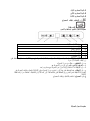
Suggestions pour résolution de problèm es
Verifier
le branchement
électrique (cf. article 2
sécurité), prise terre de
220V
Vérifier clé moteur (elle
doit être allumée)
Vérifier clé ampoule
(elle doit être allumée)
Vérifier le filtre
aluminium (nettoyer 1
fois par mois en
moyenne)
Contrôler les ampoules (
elles doivent êtres
résistantes)
Contrôler la sortie d’air
du tuyau ( rien ne doit
gêner sa sortie)
Vérifier le filtre carbone
( si cas de filtre en
carbone, remplacer 1
fois tous les 3 mois en
moyenne)
L a hotte ne
fonctionne pas
X
X
L ’ampoule de
fonctionne pas
X
X
X
L a hotte aspire
très peu
X
X
X
L ’air n’est pas
dégagé (milieu
sans tuy au)
X
X
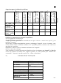
Problèmes et suggestions pour résoudre les problèmes:
Si votre appareil ne fonctionne pas:
Avant de contacter nos services:
Vérifier que votre appareil est bien branché sur une prise correcte et assurez-vous qu’il n’y pas
problème de tension.
N e p a s f ai re d e f au ss e s m an i pu la t io ns p o uv an t e n do mm a ge r l’ a pp ar ei l . A va nt d e c on t ac te r v ot r e
s er vi ce v é r i f i e r l a h o t t e e n f o n c t i o n d u t a b l e a u 1 . S i l e p r o b l è m e p e r s i s t e , c o n t a c t e r v o t r e v e n d e u r o u
u n t e c h n i c i e n compétent.
I mportant: L a liste de services à contacter est fournie avec l’appareil.
Service et pièces de rechanges:
Votre vendeur et le service peuvent vous fournir les pièces de rechanges sur demande. La liste des
services à contacter est fournie avec l’appareil. Utiliser les codes produits pour formuler une
commande. L’étiquette du produit est placée sur le filtre en aluminium.
11)
INFORMATIONS TECHNIQUES
600-900 mm
475 mm
Max 980 Min. 706 mm
mm
PUSH BUTTON
LONGUEUR
LARGEUR
LA TAILLE
MANETTE
ASPIRATION D'AIR
PUISSANCE D'AMPOULE
PUISSANCE DU MOTEUR
POUVOIR TOTAL
DIAMÈTRE DU TUYAU DE
SORTIE D'AIR
TENSION D'ALIMENTATION
336,2m3/h
1x2 W
1x110 W
112W
120 mm
220 - 240 V - 50Hz

لﺎﺠﻣ تﺎﻤﯿﻠﻌﺘﻟا ﻞﯿﻟد
ا يﺰﯾﺰﻋﻒﯾﺮﺤﻟ،
ماﺪ
ﺨﺘﺳا ﻦﻣ ﻚﻨﻜﻤﺗ فﻮﺳ ﻲﺘﻟا ﺔﻣزﻼﻟا تﺎﻣﻮﻠﻌﻤﻟا كﺎﻨھ ،ﺎﻨھ ﺔﻣﺪﻘﻤﻟا مﺎﺴﻗﻷا ﻲﻓ
نﺎﻣأو ةءﺎﻔﻜﺑ زﺎﮭﺠﻟا .ﺖﯿﺒﺜﺗ ﻞﺒﻗ ﺔﯾﺎﻨﻌﺑ تﺎﻤﯿﻠﻌﺘﻟا هﺬھ ةءاﺮﻗ ﻰﺟﺮﯾ ﻟازﺎﮭﺠ
ﻢﺴ
ﻘﻟا1 ﺔﻨﺧﺪﻤﻟا ماﺪﺨﺘﺳا ﻞﺒﻗ ﺎﮭﺗﺎﻋاﺮﻣ ﺐﺠﯾ ﻲﺘﻟا ﺔﻣﺎﮭﻟا طﺎﻘﻨﻟا
ﻢﺴﻘﻟا2 ﺔﯿﻨﻔﻟا تﺎﻔﺻاﻮﻤﻟاﻟﺔﻨﺧﺪﻤﻠ.
ﻢﺴ
ﻘﻟا3 ﺔﯿﻨﻔﻟا دﺎﻌﺑﻷاﻟﺔﻨﺧﺪﻤﻠ
ﻢﺴﻘﻟا4 ﻲﺋﺎﺑﺮﮭﻜﻟا ﻢﺳﺮﻟا ﻟﺔﻨﺧﺪﻤﻠ
ﻢﺴﻘﻟا5 لﻮﺣ تﺎﻣﻮﻠﻌﻣو ﺖﯿﺒﺜﺗ ﺐﯿﻛﺮﺗ اﺔﻨﺧﺪﻤﻟ
ﻢﺴﻘﻟا6 ماﺪﺨﺘﺳا لﻮﺣ تﺎﻣﻮﻠﻌﻣاﺔﻨﺧﺪﻤﻟ
ﻢﺴﻘﻟا7 ﺔﻧﺎﯿﺻ ﻦﻋ تﺎﻣﻮﻠﻌﻣاﺔﻨﺧﺪﻤﻟ
ﺎﮭﺗﺎﻋاﺮﻣ ﺐﺠﯾ ﻲﺘﻟا ﺔﻣﺎﮭﻟا طﺎﻘﻨﻟاو تﺎطﺎﯿﺘﺣﻻا
ﻢﺴﻘﻟا1
1 . ﺔﻣﺪﺨﻟا ﻲﻔظﻮﻣ ﻞﺒﻗ ﻦﻣ ﺐﯿﻛﺮﺘﻟا و ءﺎﺑﺮﮭﻜﻟا ﻞﯿﺻﻮﺗ ﻢﺘﯾ نأ ﺐﺠﯾ ﻦﯿﻤﻠﻤﻟا اﺪﯿﺟ ﺑ؛عﻮﺿﻮﻤﻟﺎ
2 .ﻞﯿﻐﺸﺘﻟا ﺔﻗﺎط 220-240 ﺖﻟﻮﻓ . زﺎﮭﺠﻟا ﻞﯿﻐﺸﺘﺑ ﻢﻘﺗ ﻻ ﻰﻠﻋلﺪﻌﻣ ﺔﻗﺎط ﺔﯿﺋﺎﺑﺮﮭﻛ رﻮﻛﺬﻤﻟا ﻦﻣ ﺮﺜﻛأ وأ ﻞﻗا.
3 . ﻻﺲﻤﻠﺗ ﻦﺧاﺪﻤﻟا نﻮﻜﯾ ﺎﻣﺪﻨﻋﺔﺌﻓﺪﺘﻟا ﺪﻗﻮﻣ ﺑ ﻞﺼﺘﻣ زﺎﻐﻟا ﻦﺧاﺪﻤوا ﺔﻌﻓﺮﺘﻣ رﺎﻨﻟا نﻮﻜﺗ ﺎﻣﺪﻨﻋ
.4ﺻﻮﺘﺑ ﻢﻗﻞﯿ ﻲﻓ ﺞﺘﻨﻤﻟاءﺎﺑﺮﮭﻛ ﺲﺑﺎﻗ ﻲﺿرأ.
5 .مﺎﻌﻄﻟا ﻲﮭط ﻲﻐﺒﻨﯾ ﻻ رﺎﻨﻟا ﮫﻠﺼﺗ يﺬﻟا زﺎﮭﺠﻟا ﺖﺤﺗ.
6 . ﻻا ﺐﺠﯾ ﻻﺪﺑ ىﺮﺧأ داﻮﻣ مﺪﺨﺘﺳﻦﻋ ةﺎﻔﺼﻣ زﺎﮭﺠﻟا ﻲﻓ مﻮﯿﻨﻣﻮﻟﻷا.
7 . ﻞﯿﺻﻮﺘﺑ ﻢﻘﺗ ﻻﻟا ﻲﻓ زﺎﮭﺠﻟاﺎﺑﺮﮭﻛ ﺲﺑﺎﻘ ﻞﺒﻗ ﻲﺋزﺎﮭﺠﻟا ﺐﯿﻛﺮﺗ ﻦﻣ ءﺎﮭﺘﻧﻻا.
زﺎﮭﺠﻟا جﺎﺘﻧإ ﻢﺘﯾ نﻮﻜﯿﻟﻲﺿرا
ﻊﻣ ﮫﻣﺪﺨﺘﺴﺗ ﻻءﺎﺑﺮﮭﻛ ﺲﺑﺎﻗ ﻲﺿرا ﺮﯿﻏ

8 . نود زﺎﮭﺠﻟا ﻞﯿﻐﺸﺘﺑ ﻢﻘﺗ ﻻةﺎﻔﺼﻣ مﻮﯿﻨﻣﻮﻟﻷا.
9 . ﺲﻤﻠﺗ ﻻحﺎﺒﺼﻣ ﺔﻠﯾﻮط ةﺮﺘﻔﻟ ﮫﻛﺮﺗ ﻢﺘﯾ ﺎﻣﺪﻨﻋ زﺎﮭﺠﻟا.
.10 ﺔﻟازﺈ
ﺑ ﻢﻘﺗ ﻻﺔﯾﺎﻔﺻ ﻞﯿﻐﺸﺘﻟا ﺪﯿﻗ زﺎﮭﺠﻟا نﻮﻜﯾ ﺎﻣﺪﻨﻋ مﻮﯿﻨﻣﻮﻟﻷا
.
.11 ﻖﯾﺮط ﻦﻋ ةﺮﺷﺎﺒﻣ زﺎﮭﺠﻟا ﻞﯿﻐﺸﺗ فﺎﻘﯾﺈﺑ ﻢﻘﺗ ﻻﺲﺑﺎﻘﻟا ﻦﻣ ﮫﺒﺤﺳ ﺪﻨﻋ ﻲﻓ نﻮﻜﯾ ﺎﻣ لﺎﻐﺘﺷا.ﺐﺠﯾ ﻞﺑ ﮫﻠﯿﻐﺸﺗ فﺎﻘﯾإ
ﻦﻣ ﻢﻜﺤﺘﻟا ﺔﺣﻮﻟ
.
.12 يرود ﻞﻜﺸﺑ زﺎﮭﺠﻟا ﻒﯿﻈﻨﺗ ﺐﺠﯾ ..
.13 ﻲﻠﻔﺴﻟا ﺢﻄﺴﻟا ﻦﯿﺑ عﺎﻔﺗرﻻا نﻮﻜﯾ نأ ﺐﺠﯾو ﺔﻨﺧﺪﻤﻟا ءﺎﻄﻏ ﻦﻣﻟا نﺮﻔ65 ﻢﺳ ﺔﻟﺎﺣ ﻲﻓ و ،ﺔﯿﺋﺎﺑﺮﮭﻜﻟا ناﺮﻓﻷا75
وأ زﺎﻐﻟﺎﺑ ﻞﻤﻌﺗ ﻲﺘﻟا ناﺮﻓﻸﻟ ﻢﺳﺔﻄﻠﺘﺨﻤﻟا
.14 ةﺮﻄﺧ نﻮﻜﺗ ﺪﻗ ﺎﮭﻧﻷ لﺎﻔطﻷا ﻦﻋ اﺪﯿﻌﺑ ﻒﯿﻠﻐﺘﻟا داﻮﻣ ﻰﻠﻋ ﻆﻓﺎﺣ ﻢﮭﯿﻠﻋ
.15 ا ﻰﻠﻋ ةﻼﻘﻤﻟا وأ نﺮﻔﻟا ﻊﺿو ﺪﻌﺑ ﺔﻨﺧﺪﻤﻟا ﻞﯿﻐﺸﺘﺑ ﻢﻗرﺎﻨﻟا.
.16 ةﺪﻤﻟ ﺔﻨﺧﺪﻤﻟا ﻞﯿﻐﺸﺘﺑ ﻢﻗ15 ﺪﻌﺑ ﺔﻘﯿﻗد ﺔﯿﻠﻤﻋ ﻦﻣ ءﺎﮭﺘﻧﻻاﻲﻠﻘﻟا وأ ﻲﮭﻄﻟا ﻦﻣ ءاﻮﮭﻟا ﻒﯿﻈﻨﺗ ﻞﺟأ ﻦﻣﻟا ﺔﺤﺋاﺮ
وﻟا رﺎﺨﺒﻠﻟاناﺬ ﺮﮭظ اﮭﻄﻟا ءﺎﻨﺛأﻲ
..
.17 حﺎﻤﺴﻟا لﻮﺧﺪﺑءاﻮﮭﻟا ﻲﻘﻨﻟاجرﺎﺨﻟا ﻦﻣ ﺔﻨﺧﺪﻤﻟا نﻮﻜﺗ لﺎﺣ ﻲﻓ ا ﺪﯿﻗﻞﻤﻌﻟﺎﻣﺪﻨﻋ ،ﺎﺻﻮﺼﺧو ، ﺗ ﺲﻔﻧ ﻲﻓ مﺪﺨﺘﺴ
ﻞﻤﻌﺗ ناﺮﻓأ ﻊﻣ ﺖﻗﻮﻟازﺎﻐﻟﺎﺑ
.
18. بﺮﻗﺄﺑ ﻞﺼﺗا ﺰﻛﺮﻣﻣﺪﺧتﺎ بﺎﺒﺳﻷا ﻦﻣ ﺐﺒﺳ يﻷ زﺎﮭﺠﻟا ﻞﯿﻐﺸﺗ ﻲﻓ ﺖﻠﺸﻓ اذإ.
19. ماﺪﺨﺘﺳﻻا ﻦﻋ ﺔﻤﺟﺎﻨﻟا تﺎﻗﺎﻔﺧﻹا ﻦﻋ ﺔﻟوﺆﺴﻣ ﺎﻨﺘﻛﺮﺷ نﻮﻜﺗ ﻻ ﺪﻗﻊﻣ ﻖﻔﺘﯾ ﺎﻣ ﺮﯿﻏ هﻼﻋأ ةرﻮﻛﺬﻤﻟا تاﺮﯾﺬﺤﺘﻟا.
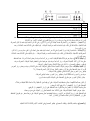
ﺔﯿﻨﻔﻟا تﺎﻔﺻاﻮﻤﻟا
ﻢﺴﻘﻟا2

1 ﺔﻨ
ﺧﺪﻣ
2 ﻢﻜﺤﺘﻟا ﺔﺣﻮﻟ
3 ﺔﻨﺧﺪﻤﻟا ﻞﻜﯿھ
4 ةﺎﻔﺼﻣمﻮﯿﻨﻣﻮﻟﻷا
5 ةءﺎﺿﻹا حﺎﺒﺼﻣ
6 جﺎﺟﺰﻟا
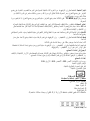
ﺔﯿﻨﻔﻟا تﺎﻔﺻاﻮﻤﻟاﺔﻨﺧﺪﻤﻟا
ﻟا لﻮﻄ
600-900 ﻢﻣ
600-900 ﻢﻣ
ضﺮﻌﻟا
475 ﻢﻣ
475 ﻢﻣ
ﻻاعﺎﻔﺗر
706 ﻢﻣ ﻞﻗﻷا980 ﺼﻗﻷا ﻢﻣﻰ
706 ﻢﻣ ﻞﻗﻷا980 ﻰﺼﻗﻷا ﻢﻣ
ﻟاﺐﻗاﺮﻤ
رﺰﻟا ﻰﻠﻋ ﻂﻐﺿا
ﺔﺷﺎﺸﻟا ﻲﻓ ﻢﻜﺤﺘﻟا رز ﻰﻠﻋ ﻂﻐﺿا
ﻂﻔﺷءاﻮﮭﻟا
650 ﺐﻌﻜﻣ
650 ﺐﻌﻜﻣ
ﻞﯿﻐﺸﺘﻟا حﺎﺒﺼﻣ
1*2 طاو
1*2 طاو
كﺮﺤﻤﻟا ةﻮﻗ
190 طاو
190 طاو
ﺔﻗﺎﻄﻟا ﻲﻟﺎﻤﺟإ
192 طاو
192 طاو
ءاﻮﮭﻟا جﺮﺨﻣ ﺐﯿﺑﺎﻧأ ﺮﻄﻗ
120 ﻢﻣ
120 ﻢﻣ
رﺎﯿﺘﻟا رﺪﺼﻣ
220-240 ﻂﻟﻮﻓ50ﺰﺗﺮھ
220-240 ﻂﻟﻮﻓ50ﺰﺗﺮھ
ﺔﯿﻨﻘﺘﻟا دﺎﻌﺑﻷا
ﻢﺴﻘﻟا3

ﺔﻈﺣﻼﻣ : ﻲھ دﺎﻌﺑﻷا ﻊﯿﻤﺟﻟﺎﺑﻢﻤ
ﻲﺋ
ﺎﺑﺮﮭﻜﻟا ﻂﺑﺮﻟا ﻂﻄﺨﻣ
ﻢﺴﻘﻟا4

ﻂﻐﺿا ﻰﻠﻋرﺰﻟا
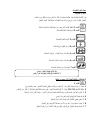
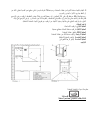
ﺖﯿﺒﺜﺘﻟا ﻂﻄﺨﻣ
ﻢﺴﻘﻟا5
1 . ﻰﻟإ نﺮﻔﻟا ﺢﻄﺳ ﻦﻣ اءﺪﺑ سﺎﯿﻗ ﺎﺼﻋ ﺔﻄﺳاﻮﺑ ﻢﯿﻘﺘﺴﻣ ﻂﺧ ﻢﺳر700 +280 : ﺮﯿﻓﻮﺗ ﻲﻓ ﺐﻏﺮﺗ ﺖﻨﻛ اذإ ﻢﻣ
ﺔﺣﺎﺴﻣ700 ﻲﻠﻔﺴﻟا ﺢﻄﺴﻟاو نﺮﻔﻟا ﻦﯿﺑ ﻢﻣﻠﻟﺔﻨﺧﺪﻤ .ﻰﻨﻤﯿﻟا فاﻮﺤﻟا ﻰﻟإ مﻮﺳﺮﻤﻟا ﻂﺨﻟا ةاذﺎﺤﻣ و ىﺮﺴﯿﻟا . ﻂﺧ ﻢﺳر
رﻮﺤﻣ67،5 ﻢﻠﻣ ﻦﯿﺒﻧﺎﺟ ﻞﻛ ﻰﻟإ زﺎﯿﺤﻧﻻا ﺰﻛﺮﻣ ﻦﻣ .ﻔﺤﻟا ﺔﻄﺳاﻮﺑ ةﺮﻔﺣ ﻞﻌﺟﺎرة ﺔﯿﺋﺎﺑﺮﮭﻜﻟا ﺎھﺮﻄﻗ6 ﻢﻠﻣلﻼﺧ ﻦﻣ
ﻢﺳر طﺎﻘﻨﻟا ﻦﻣ ﻦﯿﻨﺛا .ﻊﯿﺳﻮﺘﻟا ﻲﻏﺮﺑ ﺐﯿﻛﺮﺗ تﺎﻋﺎﻤﺸﻟا ﺖﯿﺒﺜﺗو.
La page est en cours de chargement...
La page est en cours de chargement...
La page est en cours de chargement...
La page est en cours de chargement...
La page est en cours de chargement...
La page est en cours de chargement...
-
 1
1
-
 2
2
-
 3
3
-
 4
4
-
 5
5
-
 6
6
-
 7
7
-
 8
8
-
 9
9
-
 10
10
-
 11
11
-
 12
12
-
 13
13
-
 14
14
-
 15
15
-
 16
16
-
 17
17
-
 18
18
-
 19
19
-
 20
20
-
 21
21
-
 22
22
-
 23
23
-
 24
24
-
 25
25
-
 26
26


Candy CCE616X Manuel utilisateur
- Taper
- Manuel utilisateur
- Ce manuel convient également à
dans d''autres langues
- English: Candy CCE616X User manual
Documents connexes
Autres documents
-
Hoover HDP620GBX Manuel utilisateur
-
Whirlpool ACMT 6310 / IX / 2 Mode d'emploi
-
Samsung NA64H3030AS/PC Manuel utilisateur
-
Ariston MWA 122.1 X Mode d'emploi
-
LG LB645329T1 Le manuel du propriétaire
-
Brandt SE2302W Le manuel du propriétaire
-
-
Arthur_Martin AHT6125B Manuel utilisateur