Lumination RPL Series Controls Accessory Controller Bracket Guide d'installation
- Catégorie
- Accessoires de moto
- Taper
- Guide d'installation

LED.com
© 20v23 Current Lighting Solutions, LLC. All rights reserved. Information and specifications subject to change
without notice. All values are design or typical values when measured under laboratory conditions.
Page 1 of 5
(Rev 05/25/23)
IND516-Lumination-RPL-Series-Controls-Accessory-Controller-Bracket-Installation-Guide_R01
Installation Guide
IND516
Lumination® Controls Accessory
Controller Kit Integration
(RPL Series)
BEFORE YOU BEGIN
Read these instructions completely and carefully.
WARNING/AVERTISSEMENT
RISK OF FIRE OR ELECTRIC SHOCK
• Turn power o before inspection, installation or removal.
• Properly ground electrical enclosure.
• Follow all NEC and local codes.
• Do not make or alter any open holes in an enclosure of wiring or
electrical components during kit installation.
• Fixture may fall down if not installed properly, follow installation
instructions.
• Wear safety glasses and proper aid during installation and
maintenance.
• Install this kit only in the luminaires that has the construction
features and dimensions shown in the photographs and/or
drawings.
• Above ceiling access required.
• LED Retrot Kit installation requires knowledge of luminaires
electrical systems. If not qualied, do not attempt installation.
Contact a qualied electrician.
• Luminaires wiring and electrical parts may be damaged when
drilling for installation of LED retrot kit. Check for enclosed wiring
and components.
• To prevent wiring damage or abrasion, do not expose wiring to
edges of sheet metal or other sharp objects.
• Do not make or alter any open holes in an enclosure of wiring or
electrical components during kit installation. Only those open holes
indicated in the photographs and/or drawings may be made or
altered as a result of kit installation. Do not leave any other open
holes in an enclosure of wiring or electrical components. Above
ceiling access required.
• LED Retrot Kit installation requires knowledge of luminaires
electrical systems. If not qualied, do not attempt installation.
Contact a qualied electrician.
• THIS LUMINAIRE IS PROVIDED WITH A FACTORY-INSTALLED
EMERGENCY LIGHTING PACK AND MUST BE SERVICED BY A
PERSON FAMILIAR WITH THE CONSTRUCTION AND OPERATION
OF THE PRODUCT AND THE HAZARDS INVOLVED.
RISQUES D’INCENDIE OU DE DÉCHARGES ÉLECTRIQUES
• Coupez l’alimentation avant d’’inspecter, installer ou déplacer le luminaire.
• Assurez-vous de correctement mettre à la terre le boîtier d’alimentation
électrique.
• Respectez tous les codes NEC et codes locaux
• Ne pas percer ou altérer les tr électrique durant l’installation.
• Le luminaire peut tomber s’il nest pas installé correctement, suivre les
instructions d’installation
• Porter des lunettes de sécurité et les aides appropriées lors de
l’installation et de l’entretien.
• Installez ce kit uniquement dans les appareils d’éclairage qui a les
caractéristiques de la construction et les dimensions indiquées dans les
photographies et/ou dessins.
• Accès requis au-dessus du plafond.
• L’installation du kit nécessite la connaissance des systèmes électriques
des luminaires. Si vous n’êtes pas qualié, ne tentez pas l’installation.
Contactez un électricien qualié.
• Le câblage du luminaire ainsi que ses composantes électriques peuvent
être endommagés lors du perçage requis pour l’installation de l’ensemble
de mise à niveau à DEL. Vériez le câblage et les composants.
• An de prévenir tout dommage ou abrasion aux ls électriques, évitez
que ceux-ci ne viennent en contact avec les bordures métalliques ou
d’autres ojets pointus.
• Seules les ouvertures indiquées sur les photos et dessins peuvent être
faites ou modiées lors de l’installation de l’ensemble de mise à niveau à
DEL. Ne laissez aucune ouverture dans le boitier ou le compartiment où
se trouvent les composants électriques.
• Accès requis au-dessus du plafond.
• L’installation du kit nécessite la connaissance des systèmes électriques
des luminaires. Si vous n’êtes pas qualié, ne tentez pas l’installation.
Contactez un électricien qualié.
• CE LUMINAIRE EST ÉQUIPÉ EN USINE D’UNE BATTERIE DE LUMIÈRES
D’URGENCE ET SA RÉPARATION DOIT ÊTRE CONFIÉE À UNE PERSONNE
QUI CONNAÎT BIEN LE PRODUIT ET SON FONCTIONNEMENT AINSI QUE
LES RISQUES INHÉRENTS.
ATTENTION
• DANGER - RISK OF SHOCK DISCONNECT ALL POWER AND DISABLE THE BATTERY PACK POWER BEFORE SERVICING BALLAST REPLACEMENT
REQUIRES RECONNECTION OF WIRES THAT MAY BE ENERGIZED.
• DANGER - RISQUE DE CHOC COUPER L’ALIMENTATION ET NEUTRALISER LA BATTERIE D’ACCUMULATEURS AVANT DE PROCÉDER À LA RÉPARATION
DU BALLAST LE REMPLACEMENT DU BALLAST NÉCESSITE LA RECONNEXION DE CONDUCTEURS QUI PEUVENT ÊTRE SOUS TENSION.

LED.com
© 20v23 Current Lighting Solutions, LLC. All rights reserved. Information and specifications subject to change
without notice. All values are design or typical values when measured under laboratory conditions.
Page 2 of 5
(Rev 05/25/23)
IND516-Lumination-RPL-Series-Controls-Accessory-Controller-Bracket-Installation-Guide_R01
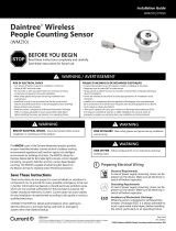
Lumination® (RPL - Series) Installation Guide
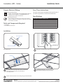
Disconnect incoming power to the xture at the panel.
1
Part identication.
Electrical bracket
Electrical components
Mount the electrical bracket with electrical components
to the existing housing with 2 provided #8x1/2”
self-drilling screws.
2
See Wiring Diagrams in the next section for
information on making wiring connections.
3
Electrical bracket
Electrical components
Housing
Housing
Installation
Description Code for Control Units
TS - Daintree Wireless Fixture Adapter (120-277 VAC)
TQ - LG Innotek Wireless Interface Module (120-277 VAC)
T1 - Daintree One (120-277VAC)
TT - Daintree EZ Connect (120-277VAC)
TZ - Daintree Enterprise (120-277VAC)
SQ - Daintree Sensor Ready (120-277VAC)
Save These Instructions
Use only in the manner intended by the manufacturer. If
you have any questions, contact the manufacturer.
Specications
Prepare Electrical Wiring
Electrical Requirements
• The RPL Controller Bracket must be supplied with 120V/277V,
50/60Hz or 347V, 50/60Hz for LXAMBAXXXXXXX and is
intended only for GE RPL Series xtures.
Grounding Instructions
• The grounding and bonding of the overall system shall be
done in accordance to local electric code of the country where
the luminaire is installed.
Tools and Components Required
• Screwdriver
• UL Listed wire connectors
Position and install sensor in the ceiling using provided hardware.
4

LED.com
© 20v23 Current Lighting Solutions, LLC. All rights reserved. Information and specifications subject to change
without notice. All values are design or typical values when measured under laboratory conditions.
Page 3 of 5
(Rev 05/25/23)
IND516-Lumination-RPL-Series-Controls-Accessory-Controller-Bracket-Installation-Guide_R01
Lumination® (RPL - Series) Installation Guide
WHITE
NEUTRAL
BLACK
LINE
WHITE
NEUTRAL
DRIVER
LIGHT
ENGINE
+
–
1-10V
REMOTE SWITCH
(OPTIONAL)
(1-10V)+
(1-10V)-
GROUND
WHITE
BLACK
VIOLET
GREY
RED
BLUE
(1-10V)+
(1-10V)-
NEUTRAL
LINE +
–
347V
NEUTRAL TRANSFORMER
ORANGE
277V+
BLACK X240V+
480V IN
NEUTRAL
347V IN
ORANGE
LINE
REMOTE TEST INPUTS
(TEST SWITCH NOT PROVIDED)
UNSWITCHED COM
SWITCHED LINE
UNSWITCHED LINE
UNSWITCHED COM
IOTA
EMBB
WHT-
WHT/BLK-
ORG/BLK+
WHT/RED (-)
WIRES
TEST BUTTON
RED/BLK (+)
RED
BLUE
WHT/BLK
WHT/BLK
RED/WHITE
BLUE/WHITE
WHITE
BLACK
DRIVER
(1-10V)+
(1-10V)-
+L
– N
+RED
-BLUE
VIOLET
GREY
RED
BLUE
LIGHT
ENGINE
+
–
(1-10V)+ REMOTE SWITCH 1-10V
(OPTIONAL)
(1-10V)-
WHITE
& BLUE
WHITE
& RED
DRIVER
CONTROL UNIT
EMI FILTER
BYPASS
NEUTRAL RED
NORMAL NEUTRAL
NORMAL LINE
GROUND
EMERGENCY LINE
LED
LOAD
WHITE
HOT BLACK (+)
& BLACK
BLUE
LOAD
YELLOW
BROWN
NEUTRAL
LINE
EMERGENCY NEUTRAL
LOAD (+)
0-10V VIOLET (+)
NEUTRAL
LINE BLACK (+)
0-10V GRAY (-)
LOAD (+)
WHT NEUTRAL
BLK
0-10V VIOLET (+)
BLK (+)
WHT
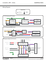
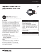
Wiring Diagrams
WHITE
NEUTRAL
BLACK
LINE
WHITE
NEUTRAL
DRIVER
LIGHT
ENGINE
+
–
1-10V
REMOTE SWITCH
(OPTIONAL)
(1-10V)+
(1-10V)-
GROUND
WHITE
BLACK
VIOLET
GREY
RED
BLUE
(1-10V)+
(1-10V)-
NEUTRAL
LINE +
–
347V
NEUTRAL TRANSFORMER
ORANGE
277V+
BLACK X240V+
480V IN
NEUTRAL
347V IN
ORANGE
LINE
REMOTE TEST INPUTS
(TEST SWITCH NOT PROVIDED)
UNSWITCHED COM
SWITCHED LINE
UNSWITCHED LINE
UNSWITCHED COM
IOTA
EMBB
WHT-
WHT/BLK-
ORG/BLK+
WHT/RED (-)
WIRES
TEST BUTTON
RED/BLK (+)
RED
BLUE
WHT/BLK
WHT/BLK
RED/WHITE
BLUE/WHITE
WHITE
BLACK
DRIVER
(1-10V)+
(1-10V)-
+L
– N
+RED
-BLUE
VIOLET
GREY
RED
BLUE
LIGHT
ENGINE
+
–
(1-10V)+ REMOTE SWITCH 1-10V
(OPTIONAL)
(1-10V)-
WHITE
& BLUE
WHITE
& RED
DRIVER
CONTROL UNIT
EMI FILTER
BYPASS
NEUTRAL RED
NORMAL NEUTRAL
NORMAL LINE
GROUND
EMERGENCY LINE
LED
LOAD
WHITE
HOT BLACK (+)
& BLACK
BLUE
LOAD
YELLOW
BROWN
NEUTRAL
LINE
EMERGENCY NEUTRAL
LOAD (+)
0-10V VIOLET (+)
NEUTRAL
LINE BLACK (+)
0-10V GRAY (-)
LOAD (+)
WHT NEUTRAL
BLK
0-10V VIOLET (+)
BLK (+)
WHT
CONTRACTOR
CONNECTION
GROUND/
LUMINAIRE
95028316 Female 95028316 Male
WHITE
NEUTRAL
BLACK
LINE
WHITE
NEUTRAL
DRIVER
LIGHT
ENGINE
+
–
1-10V
REMOTE SWITCH
(OPTIONAL)
(1-10V)+
(1-10V)-
GROUND
WHITE
BLACK
VIOLET
GREY
RED
BLUE
(1-10V)+
(1-10V)-
NEUTRAL
LINE +
–
347V
NEUTRAL TRANSFORMER
ORANGE
277V+
BLACK X240V+
480V IN
NEUTRAL
347V IN
ORANGE
LINE
REMOTE TEST INPUTS
(TEST SWITCH NOT PROVIDED)
UNSWITCHED COM
SWITCHED LINE
UNSWITCHED LINE
UNSWITCHED COM
IOTA
EMBB
WHT-
WHT/BLK-
ORG/BLK+
WHT/RED (-)
WIRES
TEST BUTTON
RED/BLK (+)
RED
BLUE
WHT/BLK
WHT/BLK
RED/WHITE
BLUE/WHITE
WHITE
BLACK
DRIVER
(1-10V)+
(1-10V)-
+L
– N
+RED
-BLUE
VIOLET
GREY
RED
BLUE
LIGHT
ENGINE
+
–
(1-10V)+ REMOTE SWITCH 1-10V
(OPTIONAL)
(1-10V)-
WHITE
& BLUE
WHITE
& RED
DRIVER
CONTROL UNIT
EMI FILTER
BYPASS
NEUTRAL RED
NORMAL NEUTRAL
NORMAL LINE
GROUND
EMERGENCY LINE
LED
LOAD
WHITE
HOT BLACK (+)
& BLACK
BLUE
LOAD
YELLOW
BROWN
NEUTRAL
LINE
EMERGENCY NEUTRAL
LOAD (+)
0-10V VIOLET (+)
NEUTRAL
LINE BLACK (+)
0-10V GRAY (-)
LOAD (+)
WHT NEUTRAL
BLK
0-10V VIOLET (+)
BLK (+)
WHT
Symbol Key
1-10V Dimming: 347V Version
1-10V Dimming: EMBB Version
Emergency Bypass with Controls
PINK
PINK
PINK

LED.com
© 20v23 Current Lighting Solutions, LLC. All rights reserved. Information and specifications subject to change
without notice. All values are design or typical values when measured under laboratory conditions.
Page 4 of 5
(Rev 05/25/23)
IND516-Lumination-RPL-Series-Controls-Accessory-Controller-Bracket-Installation-Guide_R01
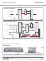
Lumination® (RPL - Series) Installation Guide
UNSWITCHED LINE
GROUND
NEUTRAL WHITE
LINE BL ACK (+) LED
LOAD
DRIVER
CONTROL UNIT
EMI FILTER
LOAD (+)
LOA D
RED
RED
LINE
LINE
BLK
BLK
BLK
BLK
WHT
WHT
WHT
WHT
WHT
WHT/BLK
WHT/BLK
NEUTRAL
WHT/RED (-)
RED/BLK (+)
TEST BUTTON
WIRES
0-10V GRAY (-)
0-10V VIOLET (+)
NEUTRAL
DRIVER
NEUTR AL
WHT/BLK
NEUTRAL
WHITE
LED
LOAD
CONTROL UNIT
COMMON NEUTRAL
SWITCHED
LINE BLACK (+)
SWITCHED LINE
GROUND
LOAD (+)
0-10V GR AY (-)
0-10V VIOLE T (+)
UNSWITCHED
NEUTRAL WHT
UNSWITCHED LINE
ORG/BLK (+)
UNSWITCHED COMMON
UNSWITCHED LINE
LED BL UE (-)
LED RED (+)
LED BL UE/WHT (-)
LED RED/WHT (+)
NEUTR AL
IOTA EMBB
EMI FILTER
LOAD
BLK
COMMON NEUTRAL
BLK
WHT
UNSWITCHED LINE
GROUND
NEUTRAL WHITE
LINE BL ACK (+) LED
LOAD
DRIVER
CONTROL UNIT
EMI FILTER
LOAD (+)
LOA D
RED
RED
LINE
LINE
BLK
BLK
BLK
BLK
WHT
WHT
WHT
WHT
WHT
WHT/BLK
WHT/BLK
NEUTRAL
WHT/RED (-)
RED/BLK (+)
TEST BUTTON
WIRES
0-10V GRAY (-)
0-10V VIOLET (+)
NEUTRAL
DRIVER
NEUTR AL
WHT/BLK
NEUTRAL
WHITE
LED
LOAD
CONTROL UNIT
COMMON NEUTRAL
SWITCHED
LINE BLACK (+)
SWITCHED LINE
GROUND
LOAD (+)
0-10V GR AY (-)
0-10V VIOLE T (+)
UNSWITCHED
NEUTRAL WHT
UNSWITCHED LINE
ORG/BLK (+)
UNSWITCHED COMMON
UNSWITCHED LINE
LED BL UE (-)
LED RED (+)
LED BL UE/WHT (-)
LED RED/WHT (+)
NEUTR AL
IOTA EMBB
EMI FILTER
LOAD
BLK
COMMON NEUTRAL
BLK
WHT
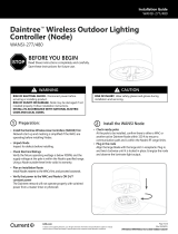
Reset button
Node fixture identification labels in a small plastic bag.
Label to be used for customer floor plans or records.
Control Indentication and Start Up
Daintree Controller
LABELS: The labels are in a small plastic bag and can be visible either on the control unit itself or near the xture labels on the outside of the
luminaire. These labels can be left in the same visible spot, or they can be placed in an area that is easy to access for easy identication.
NOTE: For further information refer to EMBB installation instructions by searching for proper model
number at www.iotaengineering.com
Control with Driver Standard
IOTA CP Series EMBB with Control
PINK
PINK

LED.com
© 20v23 Current Lighting Solutions, LLC. All rights reserved. Information and specifications subject to change
without notice. All values are design or typical values when measured under laboratory conditions.
Page 5 of 5
(Rev 05/25/23)
IND516-Lumination-RPL-Series-Controls-Accessory-Controller-Bracket-Installation-Guide_R01
Lumination® (RPL - Series) Installation Guide
* For further information on the bypass unit, refer to www.functionaldevices.com
This device complies with Part 15 of the FCC Rules. Operation is subject to the following two conditions: (1) This device may not cause harmful interference,
and (2) this device must accept any interference received, including interference that may cause undesired operation. CAN ICES-005(A)/NMB-005(A) This device
complies with part 15 of the FCC rules for the United States and Industry Canada (IC) license exempt RSS standard(s). Operation is subject to the following two
conditions: (1) This device may not cause harmful interference, and (2) this device must accept any interference received, including interference that may cause
undesired operation. Any changes or modications not expressly approved by the manufacturer could void the user’s authority to operate this equipment. This
product is intended for commercial use only.
Note: This equipment has been tested and found to comply with the limits for a Class A digital device, pursuant to part 15 of the FCC Rules. These limits
are designed to provide reasonable protection against harmful interference when the equipment is operated in a commercial environment. This equipment
generates, uses, and can radiate radio frequency energy and, if not installed and used in accordance with the instruction manual, may cause harmful interference
to radio communications. Operation of this equipment in a residential area is likely to cause harmful interference in which case the user will be required to
correct the interference at his own expense.
LG Controller (Compatible with Daintree)
LED Indicator
Reset Button &
LABELS: The labels can be visible either on the control unit itself or near the xture labels on the outside of the luminaire. These labels
can be left in the same visible spot, or they can be placed in an area that is easy to access for easy identication.
Interface Module (SQ)
EMERGENCY BYPASS OPTION: Connect the BLACK and RED
wires from the xture to the normal, non-emergency AC wires
to detect whether or not the xture is in emergency mode.
NOTE:
• See diagram to right for wire colors and descriptions.
• Self-Test Input must be from same branch circuit as normal
neutral and normal hot.
• Remote test switch is not provided.
• Remote test input is performed when input is CLOSED.
ESRB
BLUE (Emergency Hot Switched to Load)
YELLOW (Emergency Neutral)
BROWN (Emergency Hot)
RED (Normal Neutral)
BLACK (Normal Hot)
WHITE/BLACK (Self-Test Input)
VIOLET (1-10V +)
VIOLET (1-10V +)
WHITE/BLUE (Remote Test Input)
WHITE/RED (Remote Test Input)
-
 1
1
-
 2
2
-
 3
3
-
 4
4
-
 5
5


Lumination RPL Series Controls Accessory Controller Bracket Guide d'installation
- Catégorie
- Accessoires de moto
- Taper
- Guide d'installation
dans d''autres langues
Documents connexes
-
Lumination FM Series LED 9-Inch Flush Mount Ceiling Fixture Guide d'installation
-
-
-
-
-
-
-
-
-
Autres documents
-
GE current RefitTM Strip Fixture Retrofit Series Guide d'installation
-
 Daintree Networked WMZ10 People Counting Sensor Guide d'installation
-
GE current IND673 Manuel utilisateur
-
GE current LRXEMBBKIT10B Guide d'installation
-
 Lightgrid Internal Node Guide d'installation
-
 GE current IND183 Guide d'installation
-
Daintree WIT100 Manuel utilisateur
-
GE Appliances IND523 Guide d'installation
-
Evolve LED E2SC Series Guide d'installation
-
 Daintree WANSI Wireless Area Controller Guide d'installation


