
DS80HP57-001B LBT80162
Manuale Installazione
Installation Manual
Manuel d’installation
F
HP602L
HP602LG
(INCERT N° B-767-0005)
Sirena da esterno in acciaio
inox autoalimentata
Self-powered stainless steel
outdoor siren
Sirène extérieure en acier
inoxydable Autoalimentée
I GB

2 HP602L-HP602LG
SOMMARIO
1 CARATTERISTICHE GENERALI.................................................................................................................................................3
2 INSTALLAZIONE..........................................................................................................................................................................4
3 CONNESSIONI.............................................................................................................................................................................5
3.1 COLLEGAMENTO DEL MODULO ANTISCHIUMA (HP602LG)............................................................................................5
4 PROGRAMMAZIONI SIRENA......................................................................................................................................................6
4.1 PROGRAMMAZIONI DI FABBRICA......................................................................................................................................6
4.2 PROGRAMMAZIONE DURATA DELLE SUONATE..............................................................................................................6
4.3 RIFERIMENTO INGRESSI BL1 E TC1..................................................................................................................................6
4.4 RIPORTO DI STATO IMPIANTO...........................................................................................................................................6
5 GESTIONE ALLARMI...................................................................................................................................................................7
6 ESEMPIO DI COLLEGAMENTO..................................................................................................................................................8
7 CARATTERISTICHE TECNICHE.................................................................................................................................................9
CONTENTS
1 GENERAL FEATURES ..............................................................................................................................................................10
2 INSTALLATION..........................................................................................................................................................................11
3 CONNECTIONS..........................................................................................................................................................................12
3.1 FOAM PROTECTION DEVICE CONNECTION (HP602LG)................................................................................................12
4 SIREN PROGRAMMING ............................................................................................................................................................13
4.1 DEFAULT PROGRAMMING................................................................................................................................................13
4.2 SOUNDER TIME PROGRAMMING.....................................................................................................................................13
4.3 BL1 AND TC1 INPUTS REFERENCE .................................................................................................................................13
4.4 SYSTEM STATUS REPORT ...............................................................................................................................................13
5 ALARM MANAGEMENT ............................................................................................................................................................14
6 CONNECTION EXEMPLE..........................................................................................................................................................15
7 TECHNICAL SPECIFICATIONS.................................................................................................................................................16
SOMMAIRE
1 CARACTERISTIQUES GENERALES........................................................................................................................................17
2 INSTALLATION..........................................................................................................................................................................18
3 CONNEXIONS............................................................................................................................................................................19
3.1 CONNEXION DU MODULE ANTIMOUSSE (HP602LG) .....................................................................................................19
4 PROGRAMMATION SIRÉNE.....................................................................................................................................................20
4.1 PROGRAMMATION D’USINE .............................................................................................................................................20
4.2 PROGRAMMATION DE LA TEMPORISATION D’ALARME................................................................................................20
4.3 REFERENCE DES ENTREES BL1 ET TC1........................................................................................................................20
4.4 REPORT DE L'ÉTAT SYSTÈME.........................................................................................................................................20
5 GESTION D'ALARME ................................................................................................................................................................21
6 EXEMPLE DE CONNEXION ......................................................................................................................................................22
7 CARACTÉRISTIQUES TECHNIQUES.......................................................................................................................................23

HP602L-HP602LG 3
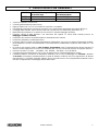
1 CARATTERISTICHE GENERALI
Modello Gabbia interna protettiva
in acciaio inox Protezione da schiuma e
sovratemperature
HP602L NO NO
HP602LG SI SI
• Coperchio esterno in acciaio inox;
• Controlli gestiti tramite microprocessore;
• Ingressi di blocco BL1 e TC1 con riferimento a positivo o a negativo.
• Possibilità di programmare il tempo di suonata in caso di mancanza permanente del segnale di blocco;
• Conteggio delle suonate: max 5 nell'arco delle 24h o nell'arco di una attivazione (transizione TC);
• Memorizzazione allarme se la centrale ha una uscita TC (tramite lampeggio del flash);
• Funzione "riporto di stato impianto": una mancanza del segnale TC fornito dalla centrale provoca un
lampeggio continuo del flash;
• Protezione da inversione di polarità batteria e alimentazione da centrale;
• Protezione antiapertura e antiasportazione;
• Funzione di blocco iniziale: alla prima alimentazione il dispositivo non suona ma attiverà il lampeggio del flash;
per predisporre la sirena al funzionamento è necessario fornire correttamente i segnali di blocco (BL) e TC da
centrale.
• In assenza del segnale di blocco oltre il tempo programmato (vedi "Programmazione durata suonata") la
sirena si arresta e genererà un nuovo ciclo di allarme solo con una successiva assenza del segnale di blocco;
• Pressione acustica a 3 metri: 104 dB(A) - vers. HP602L, 102 dB(A) - vers. HP602LG;
• Controllo interno di batteria bassa che in caso di allarme blocca il flash privilegiando la sirena;
• Il modello HP602LG è munito di un dispositivo elettronico che in caso di sabotaggio con schiuma o tentativo
di incendio (ad esempio sovratemperatura causata da fiamma ossidrica) invia una segnalazione di allarme
manomissione; si consiglia comunque l'utilizzo di una seconda sirena o di un programmatore telefonico atti a
ricevere la segnalazione di sabotaggio inviata dalla sirena.

4 HP602L-HP602LG
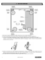
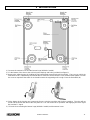
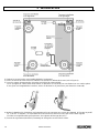
2 INSTALLAZIONE
1) Rimuovere il coperchio esterno e la gabbia di protezione (solo su modello HP602LG)
2) Fissare il fondo della sirena al muro tramite i 4 tasselli forniti utilizzando i fori previsti (vedi figura 1)
3) Sollevare il micro-switch antiapertura/asportazione (A) dopo averlo liberato dal nastro adesivo che lo blocca.
La vite su cui appoggia il micro-switch è tarata in fabbrica affinchè la leva, in presenza del coperchio, chiuda il
contatto. Se così non fosse, per irregolarità della superficie di appoggio, avvitare o svitare la vite quanto basta.
Richiudere il micro-switch (B).
4) Inserire l'accumulatore 12V 1,9Ah nell'apposito alloggiamento e collegare i faston: filo rosso al positivo, filo nero al
negativo. Alla prima alimentazione la sirena non suona e il flash lampeggia. La predisposizione al funzionamento si
avrà dopo l'applicazione dei segnali di blocco (BL) e del segnale TC.
5) Richiudere la sirena rimontando ed avvitando la gabbia interna (HP602LG) ed il coperchio.

HP602L-HP602LG 5
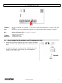
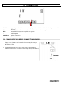
3 CONNESSIONI
TAMPER : Morsetti di appoggio per collegare i fili del micro antiapertura-asportazione e l'ingresso 24h della
centrale.
TC1: Ingresso TC per il blocco del flash da collegare al TC della centrale, riferito a positivo o a negativo
BL1: Ingresso di comando, riferito a positivo o a negativo
+: Positivo di alimentazione.
- : Negativo di alimentazione
+FLASH- : Collegamento flash
SPEAKER: Collegamento tromba
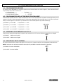
3.1 COLLEGAMENTO DEL MODULO ANTISCHIUMA (HP602LG)
• Alimentare il dispositivo collegando il filo nero al negativo del modulo
sirena. Il filo rosso è già cablato di fabbrica sul morsetto positivo del
flash.
• Collegare l'uscita tamper in serie a morsetti "TAMPER" del modulo
sirena (come mostrato in 6.0 ESEMPIO DI COLLEGAMENTO)
all'ingresso 24h della centrale.

6 HP602L-HP602LG
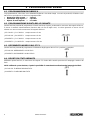
4 PROGRAMMAZIONI SIRENA
4.1 PROGRAMMAZIONI DI FABBRICA
Le programmazioni sulla sirena sono effettuabili tagliando o lasciando integri una serie di ponticelli; di fabbrica sono
tutti chiusi e specializzano la sirena nel seguente modo:
• Durata max delle suonate = 3 minuti
• Riferimento degli ingressi = a positivo
• Riporto di stato impianto = non attivo
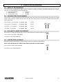
4.2 PROGRAMMAZIONE DURATA DELLE SUONATE
Questa funzione permette di programmare il ritardo max dopo il quale, perdurando la mancanza del segnale di blocco,
la sirena si arresterà autonomamente (funzione utile nel caso di taglio cavo). La sirena genererà un nuovo ciclo di
allarme con una successiva mancanza del segnale di blocco.
JP3 CHIUSO - JP4 CHIUSO: tempo suonata = 3 min
JP3 CHIUSO - JP4 APERTO: tempo suonata = 6 min
JP3 APERTO - JP4 CHIUSO: tempo suonata = 9 min
JP3 APERTO - JP4 APERTO: tempo suonata = 30 min
4.3 RIFERIMENTO INGRESSI BL1 E TC1
Questa funzione permette di programmare il riferimento degli ingressi BL1 e TC1 a positivo o a negativo.
JP5 CHIUSO: RIFERIMENTO A POSITIVO
JP5 APERTO: RIFERIMENTO A NEGATIVO
4.4 RIPORTO DI STATO IMPIANTO
Abilitando questa funzione, la mancanza del segnale TC fornito dalla centrale provocherà il lampeggio continuo del
flash.
NOTA: abilitando questa funzione, si perde la possibilità di memorizzazione allarmi tramite lampeggio del flash.
JP1 CHIUSO: FUNZIONE DISABILITATA
JP1 APERTO: FUNZIONE ABILITATA

HP602L-HP602LG 7
5 GESTIONE ALLARMI
• La sirena genera allarme solo se vengono a mancare sia il segnale TC che il segnale di blocco.
• Per bloccare un allarme in corso è sufficiente fornire il segnale blocco.
• L'ingresso TC1 (da collegare al morsetto TC delle centrali Elkron), può essere riferito a positivo o a negativo.
Chiuso al riferimento indica lo stato di impianto disattivo, azzera la segnalazione del flash ed inibisce la suonata.
Aperto indica lo stato di impianto (o settore) attivo ed abilita la sirena.
• L'ingresso BL1 è un comando di blocco riferito a positivo o a negativo. E' chiuso al riferimento in condizioni di
riposo, mentre se viene aperto genera allarme.
• Al termine del ciclo di allarme (ripristino del segnale BL), il flash continuerà a lampeggiare per segnalare l'evento
avvenuto fino a quando non viene fornito il segnale TC (disattivando l'impianto).
• Il conteggio allarmi, attivo solo se viene connesso il TC, si resetta ad ogni disattivazione dell'impianto oppure ogni
24h dall'inizio della prima suonata, a tal fine un allarme viene considerato tale solo se di durata superiore a 25
secondi.
• Collegando in parallelo TC1 e BL1 si esclude il conteggio delle suonate e la memoria allarmi.

8 HP602L-HP602LG
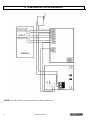
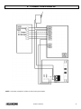
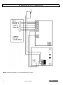
6 ESEMPIO DI COLLEGAMENTO
NOTA: l'esempio si riferisce alle programmazioni di fabbrica della sirena.

HP602L-HP602LG 9
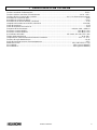
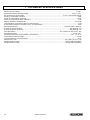
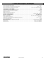
7 CARATTERISTICHE TECNICHE
Tensione nominale di alimentazione .................................................................................................................. 13.8V–
Tensione minima / massima di funzionamento ........................................................................................10.5V ÷ 15V–
Tensione di blocco ingressi NC a positivo...................................................................da 5,5 V alla tensione nominale
Assorbimento a riposo HP602L.............................................................................................................................. 9mA
Assorbimento a riposo HP602LG......................................................................................................................... 27mA
Assorbimento in allarme HP602L / HP602LG........................................................................................................ 1,3A
Lampada ad incandescenza HP602 / HP602LG.............................................................................................12V 10W
Grado di protezione................................................................................................................................................ IP43
Grado di resistenza meccanica IK.......................................................................................................................... IK06
Frequenza di funzionamento..................................................................................................min/max 1400 ÷ 1600 Hz
Pressione acustica HP602L................................................................................................................. 104 dB(A) a 3 m
Pressione acustica HP602LG.............................................................................................................. 102 dB(A) a 3 m
Accumulatore allocabile..............................................................................................12V 1.9Ah; 12V 2Ah; 12V 2.1Ah
Tamper antimanomissione ..........................................................................................................................1A @ 24V–
Temperatura di funzionamento dichiarata dal costruttore.................................................................... -25°C ÷ + 70° C
Tensione di soglia batteria bassa.........................................................................................................................10,8V
Soglia di intervento sensore di sovratemperatura...............................................................................................~ 95°C
Dimensioni in mm ...................................................................................................................243 x 285 x 92 (l x h x p)
Peso HP602L.............................................................................................................................2120 g (senza batteria)
Peso HP602LG..........................................................................................................................2550 g (senza batteria)

10 HP602L-HP602LG
1 GENERAL FEATURES
MODEL STAINLESS STEEL INTERNAL
PROTECTIVE CASE FOAM AND
OVERTEMPERATURE
PROTECTION
HP602L NO NO
HP602LG YES YES
• Stainless steel external box,
• Controls managed by microprocessor.
• BL1 and TC1 lock inputs with positive or negative reference.
• Possibility of programming sounder when lock signal is permanently down.
• Sounder counter: up to 5 over 24h or per activation sequence (TC transition)
• Alarm log for units with TC output (flasher blinking)
• System status report function: TC signal absence from control panel will cause continuous flash blinking;
• Battery polarity inversion protection and power via control unit.
• Anti-opening and anti-removal protection.
• Initial lock function: the flasher will blink and the siren will not sound at first power-up ; connect lock signal (BL)
and TC unit to set up siren for operation.
• Siren stops when the lock signal is down for longer than the programmed time. A new alarm cycle will be
generated if the lock signal goes down again.
• Acoustic pressure: 104 dB(A) - HP602L model, 102 dB(A) - HP602LG model.
• Internal low battery saver function stops the flasher and privileges the siren.
• HP602LG model is provided with an electronic device to send alarm signals in case of foam or fire tamper
(ex.: with oxyhydrogen foam); it is recommended the use of a second siren or a telephone programmer
suitable to receive the tamper signal sent by the siren.

HP602L-HP602LG 11
2 INSTALLATION
1) Remove the external cover and the internal cage (HP602LG model).
2) Fix the bottom of the siren to the wall using the rawplugs and holes provided (see figure 1).
3) Remove the adhesive tape (A) holding the anti-opening/anti-removal limit switch and lift it . The screw on which the
limit switch rests is calibrated by the manufacturer to close the contact when the cover is fitted. Either tighten or loosen
the screw as required if the switch is not closed because the supporting wall is rough. Close the limit switch (B).
4) Fit the battery in the housing and connect the fast-on: red wire to positive, black wire to negative. The siren will not
sound and the flasher will blink at the first power-on. The unit will be set for operation after applying the block signal
(BL) and the TC signal.
5) Close the siren mounting the internal cage (HP602LG model) and the external cover.

12 HP602L-HP602LG
3 CONNECTIONS
TAMPER : Supporting terminals for connect anti-opening/anti-removal limit switch wires leading to control unit
24h input.
TC1: Flasher block input. TC reference from control unit can be positive or negative.
BL1: Control block input referred to positive or negative.
+: Module power positive.
- : Power negative
+FLASH- : Flasher connection.
SPEAKER: Speaker connection.
3.1 FOAM PROTECTION DEVICE CONNECTION (HP602LG)
• Power the device by connecting the black wire to negative power
supply of siren unit. Red wire is already connected by the factory to
the positive of flash.
• Tamper terminale block is the N.C. alarm ouput of the protection
module. Provide a series connection in the tamper line (as shown in 6.0).

HP602L-HP602LG 13
4 SIREN PROGRAMMING
4.1 DEFAULT PROGRAMMING
The siren can be programmed by either cutting or keeping a number of jumpers. The default settings are all closed.
The siren can be programmed in the following way:
• Maximum siren time = 3 minutes
• Input reference = positive
• System status report = disabled
4.2 SOUNDER TIME PROGRAMMING
This function is used to program the maximum delay after which the siren will automatically stop if the lock signal
persists (this function is useful is the wire was cut). The siren will generate a new alarm cycle the next time the lock
signal goes down.
JP3 CLOSED - JP4 CLOSED: SOUNDER TIME = 3 min
JP3 CLOSED - JP4 OPEN: SOUNDER TIME = 6 min
JP3 OPEN - JP4 CLOSED: SOUNDER TIME = 9 min
JP3 OPEN - JP4 OPEN: SOUNDER TIME = 30 min
4.3 BL1 AND TC1 INPUTS REFERENCE
This function is used to program the BL1 and TC1 input references to either positive or negative.
JP5 CLOSED: POSITIVE REFERENCE
JP5 OPEN: FUNCTION ENABLED
4.4 SYSTEM STATUS REPORT
Should this function be enabled, TC signal absence will cause continuous flash blinking.
NOTE: when this function is enabled, alarm memory function won’t be available.
JP1 CLOSED: FUNCTION DISABLED
JP1 OPEN: FUNCTION ENABLED

14 HP602L-HP602LG
5 ALARM MANAGEMENT
• The siren generates an alarm only when both the TC signal and the block signal are down.
• The block signal alone is sufficient to stop an alarm in progress.
• TC1 input can be biased with both positive or negative reference. When the system is in standby, TC1 is tied to its
reference. In alarm condition TC1 is floating, no reference is applied. Should TC1 be biased with its reference
during an alarm cycle, this will cause the siren reset.
• BL1 input provides a "blocking" command to the siren when its reference is present. Conversely, it will trip an
alarm when reference is removed (at the same time of TC1).
• After blocking the alarm, the flasher will continue blinking to signal the alarm presence until the TC signal is
received (to deactivate the system).
• The alarm counter is reset either each time the system is switched off or after 24h from the beginning of the first
sounder operation. Only sounder cycles longer than 25s are considered for this purpose.
• The sounder counter and the alarm memory are cut off by connecting TC1 and BL1 in parallel.

HP602L-HP602LG 15
6 CONNECTION EXEMPLE
NOTE: connection exemple is relative to siren factory parameters.

16 HP602L-HP602LG
7 TECHNICAL SPECIFICATIONS
Nominal power voltage .......................................................................................................................................13.8V–
Minimum/maximum working voltage.........................................................................................................10.5V ÷ 15V–
NC positive input lock voltage..............................................................................................to 5.5 V at nominal voltage
Stand-by consumption HP602L..............................................................................................................................9mA
Stand-by consumption HP602LG.........................................................................................................................27mA
Alarm consumption HP602L / HP602LG................................................................................................................1.3A
HP602 / HP602LG filament bulb......................................................................................................................12V 10W
Casing degree of protection stated by manufacturer..............................................................................................IP43
IK mechanical degree of resistance (CEI 70.3 standards).....................................................................................IK06
Operating frequency .............................................................................................................. min/max 1400 ÷ 1600 Hz
Acoustic pressure HP602L .................................................................................................................104 dB(A) @ 3 m
Acoustic pressure HP602LG...............................................................................................................102 dB(A) @ 3 m
Allocable battery .........................................................................................................12V 1.9Ah; 12V 2Ah; 12V 2.1Ah
Anti-tamper feature......................................................................................................................................1A @ 24V–
Working temperature range stated by manufacturer............................................................................-25°C ÷ + 70° C
Low battery threshold voltage...............................................................................................................................10.8V
Over temperature sensor threshold.................................................................................................................... ~ 95°C
Dimensions in mm ..................................................................................................................243 x 285 x 92 (l x h x p)
Weight HP602L model..............................................................................................................2120 g (without battery)
Weight HP602L model..............................................................................................................2550 g (without battery)

HP602L-HP602LG 17
1 CARACTERISTIQUES GENERALES
Modèles Cage protectrice interne
en acier inoxydable Protection anti-mousse
et protection thermique
HP602L NON NON
HP602LG OUI OUI
• Couvercle extérieure en acier inoxydable,
• Contrôlé et géré par microprocesseur.
• Entrée de blocage par polarité positive ou négative.
• La possibilité de programmer le temps de sonnerie en cas d'absence du signal de blocage.
• Comptage d’alarme : max 5 dans les 24heures ou dans une activation par TC.
• Mémoire d’alarme (par l'intermédiaire du flash) si la Centrale ne réarme pas sa sortie TC.
• «Rapport d’état du système»: un manque du signal TC fourni par la centrale provoque un clignotement
continu du flash.
• Protection contre l'inversion de polarité de la batterie et de l’alimentation de la centrale.
• Autoprotection à l’ouverture et à l’arrachement.
• Fonction de blocage : A la mise sous tension le dispositif ne sonne pas mais le flash clignote
vous devez fournir correctement les polarités BL et TC aux de la Centrale pour la rendre opérationnelle.
• En l'absence du signal de blocage au-delà du temps programmé (voir «programmation de la durée d’alerte»)
la sirène s'arrête et ne pourra générer un nouveau cycle d’alerte que si une nouvelle absence du signal BL se
produit après une réapparition préalable de celui-ci.
• Pression acoustique à 3m: 104 dB - HP602L, 102 dB - HP602LG.
• Contrôle interne de la batterie faible qui bloque le flash privilégiant la sirène.
• Le modèle HP602LG est équipé d'un dispositif électronique qui, en cas de sabotage avec de la mousse ou
tentative thermique (p. ex. surchauffe provoquée par chalumeau) envoie une alarme effraction de
signalisation; Nous recommandons par programmation l’action d’une sortie centrale pour déclencher
l'utilisation d'une seconde sirène ou/et le téléphone pour envoyer les tentatives de sabotage de la sirène
HP602LG.

18 HP602L-HP602LG
2 INSTALLATION
1) Retirez le couvercle et la cage (modèle HP602LG seulement).
2) Fixez au fond de la sirène au mur à l'aide des vis fournies en utilisant les 4 trous (voir la Figure 1).
3) Levez le contact d’autoprotection (A) après l’avoir libéré du ruban adhésif.
La vis qui appuie le contact est d’usine calibré, en présence du couvercle pour une fixation sur une surface plane.
Si non, pour une irrégularité de la surface, vissez ou dévissez la vis juste assez pour fermer le contact (B).
4) Insérez la batterie 12V /2,1Ah dans son logement prévu et connecter aux cosses de la batterie le fil rouge au positif
(+), le fil noir au négatif (-). A la première mise sous tension la sirène ne sonne pas mais le flash clignote.
La sirène sera opérationnelle qu’en présence des signaux de blocage (BL) et TC.
5) Fermez la cage interne (HP602LG) remontage et vissage du couvercle de la sirène.

HP602L-HP602LG 19
3 CONNEXIONS
TAMPER : Bornes pour connecter les fils du contact d’autoprotection à l’entrée sabotage 24h de la centrale.
TC1: Entrée TC pour le blocage du flash par une commande TC en référence soit au positif ou au négatif
délivrée par une centrale.
BL1: Entrée de commande d’alarme en référence soit au positif ou au négatif.
+: Positif d’alimentation.
- : Négatif d’alimentation
+FLASH- : Bornes du flash.
SPEAKER: Bornes du H.P.
3.1 CONNEXION DU MODULE ANTIMOUSSE (HP602LG)
• Alimenter votre appareil en connectant le fil noir à la borne
négative de la sirène.
Le fil rouge est déjà branché usine sur la borne positif du flash.
• Connecter la sortie anti-sabotage en série aux bornes « TAMPER »
de la sirène (comme illustré dans le lien d'exemple 6.0) et l'entrée 24/24
de la Centrale.

20 HP602L-HP602LG
4 PROGRAMMATION SIRÉNE
4.1 PROGRAMMATION D’USINE
Les horaires sont disponibles sur la sirène coupant ou en laissant intacte une série de ponts ; usine sont tous fermés
et spécialisée de la sirène comme suit :
• Durée d’alarme = 3 minutes
• Entrées de référence = au positif
• Report d’état du système = non actif
4.2 PROGRAMMATION DE LA TEMPORISATION D’ALARME
Cette fonction permet de fixer le délai maximum lors d’une courte disparition de la polarité de blocage émise par la
centrale, la sirène s’arrête automatiquement à la fin du temps programmé (fonction utile dans le cas d’une coupure de
câble). La sirène génère un nouveau cycle d’alerte avec une nouvelle perte de la polarité de blocage.
JP3 FERMÉ - JP4 FERMÉ: Temporisation = 3 min
JP3 FERMÉ - JP4 OUVERT: Temporisation = 6 min
JP3 OUVERT - JP4 FERMÉ: Temporisation = 9 min
JP3 OUVERT - JP4 OUVERT: Temporisation = 30 min
4.3 REFERENCE DES ENTREES BL1 ET TC1
Cette fonction permet de programmer la gestion des entrées BL1 et TC1 soit en référence au positif ou au négatif.
JP5 FERMÉ: Référence au positif
JP5 OUVERT: Référence au négatif
4.4 REPORT DE L'ÉTAT SYSTÈME
En activant cette fonction, l'absence de signal TC1 fourni par la centrale entraînera un clignotement continu du flash.
NOTA: l’activation de cette fonctionnalité ne donne plus la possibilité de mémoire d’alarme à l'aide flash.
JP1 FERMÉ: Fonction déshabilitée
JP1 OUVERT: Fonction habilitée
La page est en cours de chargement...
La page est en cours de chargement...
La page est en cours de chargement...
La page est en cours de chargement...
-
 1
1
-
 2
2
-
 3
3
-
 4
4
-
 5
5
-
 6
6
-
 7
7
-
 8
8
-
 9
9
-
 10
10
-
 11
11
-
 12
12
-
 13
13
-
 14
14
-
 15
15
-
 16
16
-
 17
17
-
 18
18
-
 19
19
-
 20
20
-
 21
21
-
 22
22
-
 23
23
-
 24
24


dans d''autres langues
- italiano: Elkron HP602LG Guida d'installazione
- English: Elkron HP602LG Installation guide
Documents connexes
-
 Elkron KIT MP508TG/FC/IMA/L Guide d'installation
-
 Elkron HPA700M Guide d'installation
-
 Elkron HPA700P Guide d'installation
-
 Elkron DC600S/BR Guide d'installation
-
 Elkron KIT MP508TG/FC/IRA Guide d'installation
-
 Elkron KIT MP508TG/FC/IRA Guide d'installation
-
 Elkron HP375M Guide d'installation
-
 Elkron HP301A Guide d'installation
-
 Elkron HPA800 Guide d'installation
-
 Elkron CP/EXP Guide d'installation


