HeatStar HS 6000DF Le manuel du propriétaire
- Catégorie
- Chauffe-eau
- Taper
- Le manuel du propriétaire
Ce manuel convient également à

05-15 JM 50125ENERCO GROUP, INC., 4560 W. 160TH ST., CLEVELAND, OHIO 44135 • 800-251-0001
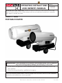
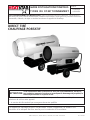
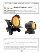
DIRECT FIRED
PORTABLE HEATER
If the information in this manual is not followed exactly, a fire or explosion
may result causing property damage, personal injury or loss of life.
WARNING:
— Do not store or use gasoline or other flammable vapors and liquids in the vicinity of this or any
other appliance.
— Service must be performed by a qualified service agency.
This is an unvented portable heater. It uses air (oxygen) from the area in which it is used. Adequate
combustion and ventilation air must be provided.
Model #
READ INSTRUCTIONS CAREFULLY: Read and follow all instructions. Place instructions in a safe
place for future reference. Do not allow anyone who has not read these instructions to assemble,
light, adjust or operate the heater.
OPERATING INSTRUCTIONS
AND OWNER’S MANUAL HS3500DF
HS6000DF

2
ENERCO GROUP, INC. |Direct Fired Portable Heater Operating Instructions and Owner’s Manual
WARNING:
FIRE, BURN, INHALATION, AND EXPLOSION HAZARD.
KEEP SOLID COMBUSTIBLES, SUCH AS BUILDING MA-
TERIALS, PAPER OR CARDBOARD, A SAFE DISTANCE
AWAY FROM THE HEATER AS RECOMMENDED BY THE
INSTRUCTIONS NEVER USE THE HEATER IN SPACES
WHICH DO OR MAY CONTAIN VOLATILE OR AIRBORNE
COMBUSTIBLES, OR PRODUCTS SUCH AS GASOLINE,
SOLVENTS, PAINT THINNER, DUST PARTICLES OR UN-
KNOWN CHEMICALS.
WARNING:
COMBUSTION BY-PRODUCTS PRODUCED WHEN US-
ING THIS PRODUCT CONTAIN CARBON MONOXIDE,
A CHEMICAL KNOWN TO THE STATE OF CALIFORNIA
TO CAUSE CANCER AND BIRTH DEFECTS (OR OTHER
REPRODUCTIVE HARM).
GENERAL HAZARD WARNING:
FAILURE TO COMPLY WITH THE PRECAUTIONS AND
INSTRUCTIONS PROVIDED WITH THIS HEATER, CAN
RESULT IN DEATH, SERIOUS BODILY INJURY AND
PROPERTY LOSS OR DAMAGE FROM HAZARDS OF FIRE,
EXPLOSION, BURN, ASPHYXIATION, CARBON MONOX-
IDE POISONING, AND/OR ELECTRICAL SHOCK.
ONLY PERSONS WHO CAN UNDERSTAND AND FOLLOW
THE INSTRUCTIONS SHOULD USE OR SERVICE THIS
HEATER.
IF YOU NEED ASSISTANCE OR HEATER INFORMATION
SUCH AS AN INSTRUCTIONS MANUAL, LABELS, ETC.
CONTACT THE MANUFACTURER.
WARNING:
NOT FOR HOME OR RECREATIONAL VEHICLE USE
WARNING:
YOUR SAFETY IS IMPORTANT TO YOU AND TO OTHERS,
SO PLEASE READ THESE INSTRUCTIONS BEFORE YOU
OPERATE THIS HEATER.
The State of California requires the following warning:
CONTENTS
WARNINGS .................................................................................. 2
SPECIFICATIONS ........................................................................... 3
OPERATION ................................................................................. 4
SAFETY DEVICES .......................................................................... 4
MAINTENANCE ............................................................................ 5
TROUBLESHOOTING .................................................................... 6
WIRING DIAGRAMS ..................................................................... 7
PARTS LIST ................................................................................... 8
WARNING:
READ THE INSTRUCTIONS GIVEN IN THIS
MANUAL BEFORE USING THE APPLIANCE.
• DO NOT USE GASOLINE, NAPHTHA OR VOLATILE
FUELS.
• THE ELECTRICAL SYSTEM TO WHICH THE APPLIANCE
IS CONNECTED MUST COMPLY WITH ALL SAFETY
REGULATIONS IN FORCE. A RESIDUAL CURRENT
CIRCUIT BREAKER MUST BE PROVIDED ON THE MAIN
DISTRIBUTION BOARD.
• UNPLUG THE HEATER BEFORE ATTEMPTING ANY
SERVICE OR MAINTENANCE.
• ALWAYS CHECK THE POWER SUPPLY CABLE BEFORE
USE. IT MUST NOT BE BENT, CRUSHED, OR ANYWAY
DAMAGED.
• THE POWER SUPPLY CABLE MUST BE REPLACED ONLY
BY QUALIFIED PERSONNEL.
• ONLY USE AN ORIGINAL H07RN-F POWER CABLE
WITH WATERPROOF PLUG.
• DO NOT TOUCH THE EXHAUST GAS OUTLET. DANGER
OF BURNS!

3Operating Instructions and Owner’s ManualENERCO GROUP, INC. |Direct Fired Portable Heater
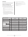
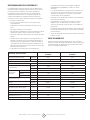
TECHNICAL SPECIFICATIONS HS 3500DF HS 6000DF
Heat input [kBTU/h] 400 610
Air flow [cfm] 2.500 2.800
Fuel Type Diesel/Kerosene/#1-2 Fuel Oil
Heat output [kBTU/h] 360 610
Fuel consumption [gal/h] 12.83 4.46
[lb/h] 19.58 30.84
Power supply
Phase 1 1
Voltage [V] 120 120
Frequency [Hz] 60 60
Electric consumption [W] 1, 170 1,040
[A] 8.30 10.50
Nozzle [USgal/h] 2.00-30° S 3.00-80°S
Pump pressure [psi] 174 217
Adjustment of combustion air flap [in] a=0.59 a=1.00
Tank capacity [gal] 27. 7 35.7
Dimensions, L x W x H [in] 62.4x27.6x39 67.9x27.6x41.2
Net Weight [lb] 222 246
IMPORTANT
Before using the heater, read and understand all instructions and
follow them carefully. The manufacturer is not responsible for
damages to goods or persons due to improper use of units.
GENERAL RECOMMENDATIONS
The direct-fired heater runs on diesel fuel. This direct combustion
heater exhausts hot air and the combustion products into
the room, while those with indirect combustion are fitted
with a flue to take the fumes away through the chimney.
Always follow local ordinances and codes when using this
heater:
• Read and follow this owner’s manual before using the
heater.
• Use only in places free of flammable vapors or high dust
content.
• Never use heater in immediate proximity of flammable
materials (the minimum distance must be 6 ft.).
• Make sure fire fighting equipment is readily available.
• Make sure sufficient fresh outside air is provided according
to the heater requirements. Direct combustion heaters
should only be used in well vented areas in order to avoid
carbon monoxide poisoning.
• Never block air inlet (rear) or air outlet (front).
• In case of very low temperatures add kerosene to the
heating oil.
• Make sure heater is always under surveillance and keep
children and animals away from it;
• Before starting the heater always check free rotation of
ventilator fan.
• Unplug heater when not in use.

4
ENERCO GROUP, INC. |Direct Fired Portable Heater Operating Instructions and Owner’s Manual
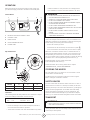
Models X Y Z
3500 DF 0.157 in 0.098 in 0.157 in
6000 DF 0.157 in 0.098 in 0.157 in
• Floors and ceilings must be made of fireproof materials in
the room where the heater is operated.
•The air inlet and outlet must never be blocked for any reason
• Install the heater on a flat, level floor in a steady position.
• It is forbidden to connect direct-fired heaters to air ducts.
WARNING
• DO NOT USE GASOLINE, NAPHTHA OR VOLATILE FUELS.
• STOP HEATER BEFORE ADDING FUELS.
• ALWAYS FILL OUTDOORS AWAY FROM OPEN FLAME
• DO NOT USE EXTERNAL FUEL SOURCE.
• DO NOT OPERATE HEATER WHERE FLAMMABLE LIQUIDS
OR VAPORS MAY BE PRESENT.
• DO NOT START HEATER WHEN CHAMBER IS HOT
• DO NOT START HEATER WHEN EXCESS FUEL HAS ACCUMU-
LATED IN THE CHAMBER.
• DO NOT PLACE COOKING UTENSILS ON TOP OF THE
HEATER.
• PLUG ELECTRICAL CORD INTO A PROPERLY GROUNDED
THREE-PRONG RECEPTACLE.
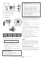
The generator can only work automatically when a control device,
such as for example a thermostat or a timer, is connected to the
generator. Connection to the generator is made by removing the
socket cover(4) and inserting the thermostat plug.
To start the machine you must:
•If connected to the thermostat, turn the switch to (ON + );
•If not connected to the thermostat, turn the switch to (ON).
When unit is started for the first time or is started after the oil
tank has been totally emptied, the flow of oil to the burner may
be impaired by air in the circuit. In this case the control box will
cut out the heater and it might be necessary to renew the starting
procedure once or twice by depressing the reset button (1).
Should the heater not start, check that oil tank
is full and depress reset button (1).
Should the heater still not work, please refer to chapter
“OBSERVED FAULTS, CAUSES AND REMEDIES”.
STOPPING THE HEATER
Set main switch (3) on “0” position or turn thermostat or other
control device on lowest setting.
The flame goes out and the fan continues to work for approx.
90sec. cooling the combustion chamber.
SAFETY DEVICES
The unit is fitted with an electronic flame control box. In case of
malfunction this box will cut in and stop the heater, at the same
time the pilot lamp in the control box reset button (1) will light up.
Heaters are also equipped with an overheat thermostat safety
cutout which will stop the heater in case of overheating. This
thermostat will reset automatically but you will have to depress
button (1) on control box before being able to restart the heater.
TRANSPORT
WARNING
• Before making any attempt to restart heater find and elimi-
nate reason of overheating.
Before heater is moved it must be stopped and unplugged. Before
moving the heater wait till it has totally cooled off and make sure
oil tank cap is securely fixed.
l k
l k
M
1 RESET BUTTON WITH CONTROL LAMP
2 CONTROL LAMP
3 MAIN SWITCH
4 ROOM THERMOSTAT PLUG
5 POWER CORD
OPERATION
Before any attempt of starting the heater is made, check that
your electrical supply conforms to the data on the model plate.
Control Board
Gap of Electrodes
Clearances
The following minimum safety clearances from materials or objects
in the surroundings of the heater must be ensured:
Sides 2.5 ft. Air Inlet 2.5 ft.
Top 6 ft. Air outlet 12 ft.
X
Z
Y
1 3 425

5Operating Instructions and Owner’s ManualENERCO GROUP, INC. |Direct Fired Portable Heater
The hot air generators with wheels must be wheeled. The
suspended version which has no wheels must be transported with
adequate machinery.
MAINTENANCE
Preventive and regular maintenance will ensure a long trouble free
life to your heater.
WARNING
• Never service heater while it is plugged in, operating or hot.
Severe burns or electrical shock can occur.
Every 50 hours of operation: disassemble filter and wash with
clean oil, remove upper body parts and clean inside and ventilator
with compressed air, check correct attachment of H.V. connectors
to the electrodes and check H.V. cables, remove burner assembly,
clean and check electrode settings, adjust according to scheme
“GAP OF ELECTRODES”.
COLUMN INTENTIONALLY LEFT BLANK

6
ENERCO GROUP, INC. |Direct Fired Portable Heater Operating Instructions and Owner’s Manual
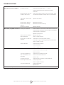
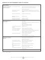
TROUBLESHOOTING
TROUBLE CAUSE SOLUTION
Motor does not start, no ignition No electrical current Check mains (should be 120 V – 1~ – 60 Hz)
Check proper positioning and functioning of switch
Check fuse
Wrong setting of room ther-
mostat or other control
Check correct setting of heater control. If thermostat, make
sure selected temperature is higher than room temperature
Thermostat or other control
defective
Replace control device
Electrical motor defective Replace electrical motor
Electrical motor bearings
defective
Replace electrical motor bearings
Burned out condenser Replace condenser
Motor starts, no ignition or cuts out Electric ignitor defective Check connection of H.V. Ieads to electrodes and transformer
Check electrodes setting (see scheme “GAP OF ELECTRODES”)
Check electrodes for cleanliness
Replace H.V. transformer
Flame control box defective Replace control box
Photocell defective Clean or replace photocell
Not enough or no fuel at all
at burner
Check state of motor-pump plastic coupling
Check fuel line system including fuel filter for possible leaks
Clean or replace oil nozzle
Solenoid defective Check electrical connection
Check thermostat LI
Clean or replace solenoid
Motor starts, heater emits smoke Not enough combustion air Make sure air inlet and outlet are free
Check setting of combustion air flap
Clean burner disc
Too much combustion air Check setting of combustion air flap
Fuel contaminated or con-
tains water
Drain fuel in tank with clean fuel
Clean oil filter
Air leaks in fuel circuit Check the seals on the ducts and the diesel filter
Not enough fuel at burner Check pump pressure
Clean or replace fuel nozzle
Too much fuel at burner Check pump pressure
Replace nozzle
Heater does not stop Solenoid Replace solenoid coil or complete solenoid
If heater still not working properly, please revert to nearest authorized dealer.

7Operating Instructions and Owner’s ManualENERCO GROUP, INC. |Direct Fired Portable Heater
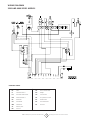
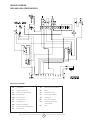
WIRING DIAGRAM
3500 AND 6000 SERIES MODELS
FU Fuse
IT Transformer H.V.
LI1 Overheat Thermostat
EV1 Solenoid Valve 1°
FO Photocell
CO Condenser
MV Fan Motor
ST Electric pilot
RV Control
TA Room Thermostat
RE Relays
AP Control Box
PA Air pressure control
RF Heater filter
FA Fan thermostat
PE Ground
DRAWING LEGEND

8
ENERCO GROUP, INC. |Direct Fired Portable Heater Operating Instructions and Owner’s Manual
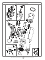
3500DF Series Direct-Fired Portable Heater
25
27
29
03
A
05
08
09
46
17
10
06 12
20
11
57
19
33
32
45
18
22
23
21
19
24
26
28
35
31
36 44
42
85
14
82 84
83
76
75
B
65
66 67
69
51
52
53
56
58
63
64
59
90
77
78
76
70
72
74
71 73
79
91
92
93
94
95
96
100
98 99
101
94
102
01
103
16 14 17
14
13
86
108
107
87
106
104 105
14
16
14
A
33
B
Optional
15
30
109
109
110 111

9Operating Instructions and Owner’s ManualENERCO GROUP, INC. |Direct Fired Portable Heater
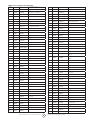
3500DF Series Direct-Fired Portable Heater
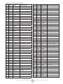
POS P/N ALT # DESCRIPTION
01 40494 G06408-9010 Outlet cone
03 50446 G06230 Combustion chamber
05 50447 G06233-9010 Upper body
06 40495 G06409-9010 Lower body
08 50160 E10678-110 Motor AACO
09 50161 E 112 3 0 Capacitor AACO
08 E10771 Motor SIMEL
09 E10771-1 Capacitor SIMEL
10 50163 G06125-9010 Air conveyor
11 50165 T10260 Fan
12 50167 P30169 Inlet grill
13 5 0 051 I40330 Flex diesel pipe
14 50729 I20104 Iron fitting
15 50 410 02 AC 513 Diesel pre-heaters filter kit
16 50054 G06104-9005 Filter support bracket
17 50055 I40329 Flex diesel pipe
18 50 451 P20176-9005 Handle
19 40477 C30355 Pipe cap
20 50058 P20177-9005 Support
21 50060 I40331 Flex diesel pipe
22 50061 I30696 Suction pipe
23 50063 I30737 Brass fitting
24 50064 G06068-9005 Power cord support
25 50170 G06127-9005 Fuel tank
26 50070 C30367 Tank cap
27 G06465-9005 Wheel axle
28 G06106-9005 Wheels axle support bracket
29 C10510 Wheel
30 50513 M20507 Cotter pin
31 40532 I25020 Drain cap
32 40479 C30375 O-ring
33 50434 G00248 El. control box
35 50077 P 5 0127 Control box cover
36 40496 G06410-9010 Base
42 50057 C 30319 Hole cap
44 5 0 411 C30372 Cable protection
45 50085 E50102 Safety thermostat
46 G06072 Spacer
51 50246 G06153 El. control box panel
52 50093 E20508 Fuse holder
53 50092 E 10313 Fuse
56 E20319 Ground terminal board
57 50097 E 1112 5 Relay
58 50731 E20305 Terminal board
59 50319 E10930 H.T. Transformer
63 50320 E40124 Flame control box
64 G06073 Support plate
65 5 0 013 E10102-P Switch
66 5 0 012 E20640 Thermostat plug
67 5 0 011 E20665 Thermostat plug cover
68 50009 E30443-1 Power cord
69 50008 E 11 0 3 0 Lamp
70 50321 T20357 Nozzle
71 50126 G01077 Diffuser ring
72 50440 I33005 Nozzle support
73 50425 G06228 Burner support disc
74 50131 I31034 Brass lock nut
76 50133 I40192 Micropipe
77 50048 E 10215 Ignition electrode
78 50322 G02078 H.T. Cable connect.
79 50323 E50328 Photocell
82 50442 T20410-1 Diesel pump
83 50140 T 2 0118 Solenoid coil
84 50141 T 2 0117 Solenoid valve body
85 50195 E 10513 Motor-pump coupling AACO
85 50237 E10698 Motor-pump coupling SIMEL
86 5014 4 T20241 Filter seal kit
87 50145 T20242 Filter cartridge
90 50325 E20 418 Stop button protection
91 50336 E50327 Photoresistor support
92 40492 G06406-9010 Pressure switch support bracket
93 50337 E 50 4 41 Pressure switch
94 40501 I40335 Silicone pipe
95 50429 I31131 Brass hose connection
96 50433 T20442 Solenoid valve cable
98 50450 G06266 Blast tube
99 50 413 E20671 Terminal board
100 5 0 419 G06183 Air adjustment shutter
101 50081 I20325 Fitting
102 50079 I 3113 0 Brass hose connection
103 50024 T20201 Diesel filter
104 50025 T20234 Filter seal kit
105 50030 T20206 Filter cartridge
106 5 0251 T 20212 Filter container
107 50082 E20953 Cable fastener
108 50083 E20954 Cable fastener nut
109 40533 M 2 0111 Washer
110 E20965 Cable fastener nut
111 E20964 Cable fastener

10
ENERCO GROUP, INC. |Direct Fired Portable Heater Operating Instructions and Owner’s Manual
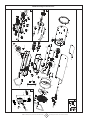
6000DF Series Direct-Fired Portable Heater
25
27
29
03
A
05
15
08
09
46
17
10
06
01
04
12
20
11
16 14 17
14
13
57
19
33
32
45
18
22
23
21
19
24
26
28
35
31
36 44
42
86
87
07
85
14
82 84
83
76
75
B
65
66 67
69
51
52
53
56
58
63
64
59
90
77
78
76
70
72
74
71 73
79
91
92
93
94
95
96
100
98 99
101
94
102
A
15
33
B
30
103
103
104 105

11 Operating Instructions and Owner’s ManualENERCO GROUP, INC. |Direct Fired Portable Heater
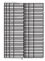
6000DF Series Direct-Fired Portable Heater
POS P/N ALT # DESCRIPTION
01 50027 G06139-9010 Outlet cone
03 50460 G06232 Combustion chamber
04 G06143-9010 Panel
05 50 4 61 G06235-9010 Upper body
06 50462 G06238-9010 Lower body
07 4 0519 G06397 Air conveyor
08 50454 E10704-110 Motor AACO
09 E 1124 9 Capacitor AACO
08 E10772 Motor SIMEL
09 E10772-1 Capacitor SIMEL
10 50463 G06239-9010 Air conveyor
11 50049 T10263 Fan
12 50050 P 3 0129 Inlet grill
13 5 0 051 I40330 Flex diesel pipe
14 50729 I20104 Iron fitting
15 50053 T20239 Diesel pre-heated filter
16 50054 G06104-9005 Filter support bracket
17 50055 I40329 Flex diesel pipe
18 505 41 P20176-9005 Handle
19 40477 C30355 Pipe cap
20 P20180-9005 Support
21 40331 I40331 Flex diesel pipe
22 50466 I30698 Suction pipe
23 50063 I30737 Brass fitting
24 50064 G06068-9005 Power cord support
25 50457 G06146-9005 Fuel tank
26 50070 C30367 Tank cap
27 G06465-9005 Wheel axle
28 50456 G06107-9005 Wheels axle support bracket
29 C10510 Wheel
30 M20507 Cotter pin
31 40532 I25020 Drain cap
32 40479 C30375 O-ring
33 40481 G00251 El. control box
35 50077 P 5 0127 Control box cover
36 40497 G06411-9010 Base
42 50453 C30323 Cable protection
44 5 0 411 C30372 Cable protection
45 50085 E50102 Safety thermostat
46 G06072 Spacer
51 50246 G06153 El. control box panel
52 50093 E20508 Fuse holder
53 50092 E 10313 Fuse
56 E20319 Ground terminal board
57 50097 E 1112 5 Relay
58 50731 E20305 Terminal board
59 50099 E10917-2 H.T. Transformer
63 50320 E40124 Flame control box
64 G06073 Support plate
65 5 0 013 E10102-P Switch
66 5 0 012 E20640 Thermostat plug
67 5 0 011 E20665 Thermostat plug cover
68 50009 E30443-1 Power cord
69 50008 E 11 0 3 0 Lamp
70 50006 T20327 Nozzle
71 50465 G07025 Diffuser ring
72 50440 I33005 Nozzle support
73 50459 G06229 Burner plate
74 50131 I31034 Brass lock nut
76 4 0120 I40192 Micropipe
77 50134 E 10215 Ignition electrode
78 50135 G02076 H.T. Cable connect.
79 50323 E50328 Photocell
82 T20411-1 Diesel pump
83 50140 T 2 0118 Solenoid coil
84 50141 T 2 0117 Solenoid valve body
85 50143 E 10514 Motor-pump coupling AACO
85 50237 E10698 Motor-pump coupling SIMEL
86 5014 4 T20241 Filter seal kit
87 50145 T20242 Filter cartridge
90 50325 E20 418 Stop button protection
91 50336 E50327 Photoresistor support
92 40492 G06406-9010 Pressure switch support bracket
93 50337 E 50 4 41 Pressure switch
94 40501 I40335 Silicone pipe
95 50429 I31131 Brass hose connection
96 50433 T20442 Solenoid valve cable
98 50235 G06412 Blast tube
99 50 413 E20671 Terminal board
100 5 0 419 G06183 Air adjustment shutter
101 50081 I20325 Fitting
102 50079 I 3113 0 Brass hose connection
103 40533 M 2 0111 Washer
104 E20965 Cable fastener nut
105 E20964 Cable fastener
107 50082 E20953 Cable fastener
108 50083 E20954 Cable fastener nut
109 40533 M 2 0111 Washer
110 E20965 Cable fastener nut
111 E20964 Cable fastener

ENERCO GROUP, INC., 4560 W. 160TH ST., CLEVELAND, OHIO 44135 • 800-251-0001
HeatStar is a registered trademark of Enerco Group, Inc.
© 2004, ENERCO GROUP, INC. All rights reserved
WARNING:
USE ONLY MANUFACTURER’S REPLACEMENT PARTS. USE OF ANY OTHER PARTS
COULD CAUSE INJURY OR DEATH. REPLACEMENT PARTS ARE ONLY AVAILABLE
DIRECT FROM THE FACTORY AND MUST BE INSTALLED BY A QUALIFIED SERVICE
AGENCY.
PARTS ORDERING INFORMATION:
PURCHASING: Accessories may be purchased at any HeatStar local dealer or direct
from the factory
FOR INFORMATION REGARDING SERVICE
Please call Toll-Free 800-251-0001 • www.enerco.com
Our office hours are 8:00 AM – 5:00 PM, EST, Monday through Friday.
Please include the model number, date of purchase, and description of problem in all
communication.
LIMITED WARRANTY
The company warrants this product to be free from imperfections in material or workmanship,
under normal and proper use in accordance with instructions of The Company, for a period
of one year from the date of delivery to the buyer. The Company, at its option, will repair or
replace products returned by the buyer to the factory, transportation prepaid within said one
year period and found by the Company to have imperfections in material or workmanship.
If a part is damaged or missing, call our Technical Support Department at 800-251-0001.
Address any Warranty Claims to the Service Department, Enerco Group, Inc., 4560 W. 160TH
ST., Cleveland, Ohio 44135. Include your name, address and telephone number and include
details concerning the claim. Also, supply us with the purchase date and the name and address
of the dealer from whom you purchased our product.
The foregoing is the full extent of the responsibility of the Company. There are no other
warranties, express or implied. Specifically there is no warranty of fitness for a particular
purpose and there is no warranty of merchantability. In no event shall the Company be liable for
delay caused by imperfections, for consequential damages, or for any charges of the expense
of any nature incurred without its written consent. The cost of repair or replacement shall be
the exclusive remedy for any breach of warranty. There is no warranty against infringement of
the like and no implied warranty arising from course of dealing or usage of trade. This warranty
will not apply to any product which has been repaired or altered outside of the factory in any
respect which in our judgment affects its condition or operation.
Some states do not allow the exclusion or limitation of incidental or consequential damages, so
the above limitation or exclusion may not apply to you. This Warranty gives you specific legal
rights, and you may have other rights which vary from state to state.
Enerco Group, Inc. reserves the right to make changes at any time, without notice or
obligation, in colors, specifications, accessories, materials and models.
OPERATING INSTRUCTIONS
AND OWNER’S MANUAL
READ INSTRUCTIONS CAREFULLY: Read and follow all instructions. Place instructions in a safe
place for future reference. Do not allow anyone who has not read these instructions to assemble,
light, adjust or operate the heater.
Model #
HS3500DF
HS6000DF

05-15 JM 50125ENERCO GROUP, INC., 4560 W. 160TH ST., CLEVELAND, OHIO 44135 • 800-251-0001
Model #
HS3500DF
HS6000DF
GUIDE D’UTILISATION ET INSTRUC-
TIONS DE FONCTIONNEMENT
DIRECT TIRÉ
CHAUFFAGE PORTATIF
LISEZ SOIGNEUSEMENT LES INSTRUCTIONS : Lisez et observez toutes les instructions. Conservez les in-
structions pour vous y référer ultérieurement. Interdisez à quiconque n’ayant pas lu les présentes instructions
d’assembler, d’allumer, de régler ou de faire fonctionner cet appareil de chauffage.
Si les informations dans ce manuel ne sont pas suivis exactement, un feu ou
une explosion peuvent s’ensuivre en provoquant le dommage de propriété, la
blessure personnelle ou la perte de vie.
ATTENTION:
— Ne conserver pas ou utiliser de l’essence ou d’autres vapeurs inflammables et de liquides aux
alentours de cela ou autre appareil.
— Le service doit être exécuté par une agence de service qualifiée.
Cet appareil de chauffage portatif n’est pas ventilé. Il utilise l’oxygène de l’air ambiant. Une
circulation d’air adéquate doit être assurée pour la combustion et la ventilation.

AVERTISSEMENT : DANGER D’INCENDIE,
DE BRÛLURE, D’EXPLOSION ET D’INHALATION.
CONSERVEZ LES MATÉRIAUX COMBUSTIBLES TELS QUE
LES MATÉRIAUX DE CONSTRUCTION, LE PAPIER ET LE
CARTON À UNE DISTANCE SÉCURITAIRE DE L’APPAREIL
DE CHAUFFAGE COMME LE RECOMMANDENT LES
INSTRUCTIONS. N’UTILISEZ JAMAIS L’APPAREIL DE
CHAUFFAGE DANS UN LOCAL QUI CONTIENT OU
RISQUE DE CONTENIR DES PARTICULES COMBUSTIBLES
EN SUSPENSION DANS L’AIR OU DES PRODUITS TELS
QUE
DE L’ESSENCE, DES SOLVANTS, DU DILUANT À
PEINTURE, DES PARTICULES DE POUSSIÈRE OU DES
PRODUITS CHIMIQUES INCONNUS.
AVERTISSEMENT : L’UTILISATION DE CET APPAREIL
CRÉE DES SOUS-PRODUITS DE COMBUSTION
CONTENANT DU MONOXYDE DE CARBONE, UN
PRODUIT CHIMIQUE RECONNU
PAR L’ÉTAT DE LA CALIFORNIE COMME CAUSE
DE CANCER ET D’ANOMALIES CONGÉNITALES (OU
AUTRES RISQUES POUR LA REPRODUCTION).
AVERTISSEMENT GÉNÉRAL DE
DANGER :
LE NON-RESPECT DES MESURES DE PRÉVENTION
ET INSTRUCTIONS FOURNIES AVEC CET APPAREIL
DE CHAUFFAGE RISQUE DE CAUSER LA MORT,
DES BLESSURES GRAVES ET DES DOMMAGES OU
DES PERTES MATÉRIELLES RÉSULTANT D’INCENDIE,
D’EXPLOSION, DE BRÛLURE, D’ASPHYXIE,
D’INTOXICATION AU MONOXYDE DE CARBONE
OU D’ÉLECTROCUTION.
SEULES LES PERSONNES APTES À COMPRENDRE ET À
RESPECTER LES INSTRUCTIONS DEVRAIENT UTILISER
OU EFFECTUER L’ENTRETIEN DE CET APPAREIL DE
CHAUFFAGE.
SI VOUS AVEZ BESOIN D’AIDE OU D’INFORMATION
AU SUJET DE L’APPAREIL DE CHAUFFAGE (MANUEL
D’INSTRUCTIONS, ÉTIQUETTES, ETC.), VEUILLEZ
COMMUNIQUER AVEC LE FABRICANT.
AVERTISSEMENT : NON CONÇU POUR UNE
UTILISATION DANS LA MAISON OU UN VÉHICULE
RÉCRÉATIF.
AVERTISSEMENT : VOTRE SÉCURITÉ
PERSONNELLE ÉTANT IMPORTANTE POUR TOUS,
VEUILLEZ LIRE LES INSTRUCTIONS AVANT
D’UTILISER CET APPAREIL DE CHAUFFAGE.
L’État de la Californie exige que l’avertissement suivant
soit fourni :
AVERTISSEMENT :
LISEZ LES INSTRUCTIONS DONNÉES
DANS CE MANUEL AVANT LE FAIT
D’UTILISER L’APPAREIL.
• LE SYSTÈME ÉLECTRIQUE AUQUEL L’APPAREIL EST
RACCORDÉ DOIT SE PLIER À TOUS LES RÈGLEMENTS
DE SÉCURITÉ DANS LA FORCE. UN DISJONCTEUR
ACTUEL RESTANT DOIT ÊTRE FOURNI SUR LE CONSEIL
DE DISTRIBUTION PRINCIPAL.
• DÉBRANCHEZ LE CHAUFFAGE AVANT LE FAIT
D’ESSAYER N’IMPORTE QUEL SERVICE OU
MAINTENANCE.
• VÉRIFIEZ TOUJOURS LE CÂBLE D’ALIMENTATION
ÉLECTRIQUE AVANT L’UTILISATION. IL NE DOIT PAS
ÊTRE TOURNÉ, ÉCRASÉ, OU NUI EN TOUT CAS .
• LE CÂBLE D’ALIMENTATION ÉLECTRIQUE DOIT ÊTRE
REMPLACÉ SEULEMENT PAR LE PERSONNEL QUALIFIÉ.
• UTILISEZ SEULEMENT UN CÂBLE D’ALIMENTATION
de H07RN-F ORIGINAL AVEC LA PRISE DE COURANT
IMPERMÉABLE.
• NE TOUCHEZ PAS L’ISSUE DE GAZ D’ÉCHAPPEMENT.
LE DANGER DE BRÛLE!
CONTENTS
AVERTISSEMENTS ........................................................................ 2
SPÉCIFICATIONS .......................................................................... 3
OPÉRATION ................................................................................. 4
ARTIFICES DE SÉCURITÉ ............................................................... 4
ENTRETIEN ................................................................................... 5
ANOMALIES DE FONCTIONNEMENT CAUSES ET SOLUTIONS ....... 6
SCHÉMAS DE CONNEXIONS ........................................................ 7
LISTE DE PARTIES .........................................................................8
IMPORTANT
Avant d’utiliser le générateur, nous vous prions de lire
attentivement toutes les instructions pour l’emploi, mentionnées
ci-après et d’en suivre scrupuleusement les indications. Le
constructeur n’est pas responsable pour les dommages aux choses
et/ou per-rès, sonnes dus à une utilisation impropre de l’appareil.

2
ENERCO GROUP, INC. |Direct Fired Portable Heater Operating Instructions and Owner’s Manual
TECHNICAL SPECIFICATIONS HS 3500DF HS 6000DF
Puisance termique en entrée [kBTU/h] 400 610
Débit d’air [cfm] 2.500 2.800
Type du Combustible Le gazole/Pétrole / * 1-2 Fuel
Puisance termique en sortie [kBTU/h] 360 610
Consommation [gal/h] 12.83 4.46
[lb/h] 19.58 30.84
Alimentation
électrique
Phase 1 1
Tension [V] 120 120
Fréquence [Hz] 60 60
Puissance électrique [W] 1, 170 1.040
[A] 8.30 10.50
Gicleur [USgal/h] 2,00-30° S 3.00-80°S
Pression pompe [psi] 174 217
Temperature max dans la gaine [°F] a=0.59 a=1.00
Tirage minimum nécessaire [in WC] 27. 7 35.7
Capacité réservoir [gal] 62.4x27.6x39 67.9x27.6x41.2
Dimensions, L x P x H [in] 217 174
Net Weight [lb] 222 246
RECOMMANDATIONS GENERALES
Le chauffage direct-tiré fonctionnent au fuel. Les générateurs à
combustion directe répandent dans l’air ambiant, de l’air chaud
et les produits de la combustion, alors que les générateurs
à combustion in-directe sont dotés d’un raccord permettant
d’éliminer les fumées à tra-vers un conduit de cheminée. Les
conditions d’installation et d’utilisation doivent respecter les
normes et les lois en vigueur relatives à l’utilisation de l’appareil
Il convient de s’assurer que:
• les instructions contenues dans ce livret soient suivies
scrupuleusement;
• le générateur ne soit pas installé dans des locaux où il y
aurait
• des risques d’explosion ou d’incendie;
• des matériaux inflammables ne soient pas déposés à côté de
l’appareil (la distance minimum doit être de 2 mètres)
• de mesures suffisantes de prévention anti-incendie aient été
prévues
• l’aération du local dans lequel se trouve le générateur soit
garantie et suffisante pour les nécessités du générateur, et
en particulier, pour le générateurs à combustion directe le
renouvellement d’air doit être évalué enconsidérant que ce
générateur envoie dans la pièce aussi bien de l’air chaud que
les produits de combustion;
• le générateur soit installé près d’une cheminée pour
l’évacuation des fumées (voir paragraphe “PLAN DE
MONTAGE DE LA CHEMINEE”) et relié à un coffret
électrique.
• il n’y ait pas d’obstacles ou d’obstructions à l’aspiration et
à la sortie de l’air, tels que des toiles ou des couvertures
étendues sur l’appareil ou sur les parois, ou des objets
encombrants à côté du générateur;
• du kérosène soit rajouté dans le réservoir si la température
de la pièce est très basse;
• le générateur soit contrôlé avant sa mise en marche et
régulière- ment surveillé durant son utilisation; il faut
éviter que des enfants ou des animaux non surveillés s’en
approchent;
• au début de chaque période d’utilisation, avant de brancher
la fiche dans la prise électrique, contrôler que le ventilateur
tourne librement;
• à la fin de chaque période d’utilisation enlever la fiche de la
prise de courant.
MISE EN MARCHE
Avant de mettre en marche le générateur et donc, avant de le
brancher au réseau électrique d’alimentation, il faut contrôler que
les caractéristiques du réseau électrique correspondent à celles
écrites sur la plaque de fabrication.

3Operating Instructions and Owner’s ManualENERCO GROUP, INC. |Direct Fired Portable Heater
Trou des electrodes
• les Étages et les plafonds doit être fait du matériel ignifugé
dans la pièce où le chauffage est fait marcher.
• l’arrivée aérienne et l’issue ne doit jamais être bloqué pour
aucune raison.
• Installent le chauffage sur un appartement, l’étage de niveau
dans un post-ion régulier.
• Cela est interdit de raccorder des chauffages direct-tirés aux
conduits de ventilation.
AVERTISSEMENT :
• N’EMPLOYEZ PAS D’ESSENCE, DE NAPHTE OU DE
PRODUITS COMBUSTIBLES VOLATILS.
• ARRÊTEZ L’APPAREIL DE CHAUFFAGE AVANT D’Y
AJOUTER DU COMBUSTIBLE.
1 BOUTON REARMEMENT AVEC LAMPE TEMOIN
2 LAMPE TEMOIN D’ALIMENTATION
3 INTERRUPTEUR MARCHE-ARRET
4 PRISE THERMOSTAT D’AMBIANCE
5 CABLE ELECTRIQUE
Tableau de commande
l k
l k
M
• REMPLISSEZ TOUJOURS LE RÉSERVOIR À L’EXTÉRIEUR,
LOIN D’UNE FLAMME NUE.
• N’UTILISEZ PAS DE SOURCE DE COMBUSTIBLE EX-
TERNE.
• NE FAITES PAS FONCTIONNER L’APPAREIL DE
CHAUFFAGE SI DES VAPEURS OU DES LIQUIDES IN-
FLAMMABLES RISQUENT D’ÊTRE PRÉSENTS.
• NE DÉMARREZ PAS L’APPAREIL DE CHAUFFAGE SI LA
CHAMBRE DE COMBUSTION EST CHAUDE.
• NE DÉMARREZ PAS L’APPAREIL DE CHAUFFAGE SI UN
SURPLUS DE COMBUSTIBLE S’EST ACCUMULÉ DANS
LA CHAMBRE DE COMBUSTION.
• NE PLACEZ PAS D’USTENSILES DE CUISSON SUR
L’APPAREIL DE CHAUFFAGE.
• BRANCHEZ LE CORDON ÉLECTRIQUE DANS UNE PRISE À
TROIS TROUS ADÉQUATEMENT MISE À LA TERRE.
Le générateur peut fonctionner en mode automatique uniquement
lorsqu’un dispositif de contrôle est connecté (par ex. un
thermostat ou une montre). La connexion au générateur doit être
faite en retirant le couvercle de la prise (4) et en branchant la fiche
du thermostat.
Pour démarrer la machine:
•si elle est pilotée par le thermostat, placer l’interrupteur sur la
position (ON + );
•si elle n’est pas pilotée par le thermostat, placer l’interrupteur
sur la position (ON).
A la première mise en service ou après la vidange totale du circuit
du fuel, le flux du fuel au gicleur peut être insuffisant et causer
l’intervention du coffret de contrôle de la flamme; le générateur
alors s’arrête.
Dans ce cas après avoir attendu une minute, pousser le bouton de
réarmement et faire redémarrer l’appareil.
Au cas où la machine ne fonctionnerait pas, les premières
opérations à faire sont les suivantes:
1.Contrôler que le réservoir contienne encore du fuel;
2.Pousser le bouton de réarmement (1);
3.Si après ces opérations le générateur ne fonctionne
pas, il faut consulter le paragraphe “ANOMALIES DE
FONCTIONNEMENT,
ARRET
Pour arrêter le fonctionnement du générateur il faut mettre
l’interrupteur (2) sur la position “0” et agir sur le dispositif de
contrôle, (parex., en réglant le thermostat sur une température
plus basse). La flamme s’éteint mais le ventilateur continue
de fonctionner pendant environ 90 secondes pour refroidir la
chambre de combustion.
DISPOSITIFS DE SECURITE
Le générateur est muni d’un coffret électronique pour le contrôle
de la flamme. En cas de mauvais fonctionnement ce coffret
provoque l’arrêt du générateur et l’allumage de la lampe témoin
du bouton de réarmement. Un thermostat de surchauffe intervient
Déblayages
Les déblayages de sécurité minimaux suivants du matériel ou des
objets dans les environs du chauffage doivent être garantis :
Côtés 2.5 ft. Arrivée Aérienne 2.5 ft.
6 Premiers ft. Issue aérienne 12 ft.
Models X Y Z
3500DF 0.157 in 0.098 in 0.157 in
6000DF 0.157 in 0.098 in 0.157 in
X
Z
Y
1 3 425

4
ENERCO GROUP, INC. |Direct Fired Portable Heater Operating Instructions and Owner’s Manual
et provoque l’interruption de l’alimentation du fuel si le générateur
surchauffe: le thermostat se réarme automatiquement quand
la température de la chambre de combustion diminue jusqu’à
rejoindre la valeur maximale admise. Avant de remettre en marche
le générateur il faut trouver et éliminer la cause qui a produit la
surchauffe (par ex. obstruction de l’entrée ou de la sortie de l’air,
arrêt du ventilateur). Pour faire redémarrer le générateur il faut
pousser le bouton de réarmement (1) et répéter les instructions
spécifiques du paragraphe “MISE EN MARCHE”.
TRANSPORT ET DEPLACEMENT
ATTENTION
• Avant de déplacer l’appareil il faut:
• Arrêter le générateur en suivant les indications du para-
graphe “ARRET”;
• Débrancher l’alimentation en enlevant la fiche de la prise de
courant;
• Attendre que le générateur soit froid.
Avant de soulever ou de déplacer le générateur il faut s’assurer
que le bouchon du réservoir soit bien fixé.
Le générateur peut être fourni dans une version mobile, muni de
roues, ou dans une version suspendue, monté sur une structure
de support avec des ancrages pour le fixage qui doit être effectué
avec l’aide de cordes ou de chaines. Dans le premier cas, pour le
transport il est suffisant de saisir le générateur par la poignée de
soutien et de le faire glisser sur les roues. Dans le deuxième cas
le soulèvement doit être effectué avec un chariot élévateur ou un
équipement similaire.
ENTRETIEN
Pour que l’appareil fonctionne régulièrement, il est nécessaire de
nettoyer périodiquement la chambre de combustion, le brûleur et
le ventilateur.
ATTENTION
• Avant de commencer une quelconque opération d’entretien
il faut:
• Arrêter le générateur selon les indications du paragraphe
“ARRET”;
• Débrancher l’alimentation électrique en enlevant la fiche de
la prise de courant;
• Attendre que le générateur soit froid.
Toutes les 50 heures de fonctionnement il est nécessaire de:
•Démonter la cartouche du filtre, l’extraire et la nettoyer avec
du fuel propre;
•Démonter la carrosserie externe cylindrique et nettoyer la
partie interne et les pales du ventilateur;
•Contrôler l’état des câbles et des connexions haute tension
sur les électrodes;
•Démonter le brûleur et en nettoyer les différentes parties,
nettoyer les électrodes et régler leur distance en respectant
les données du schéma “TROU DES ELECTRODES”.
LA COLONNE A INTENTIONNELLEMENT
QUITTÉ LE BLANC

5Operating Instructions and Owner’s ManualENERCO GROUP, INC. |Direct Fired Portable Heater
ANOMALIES DE FONCTIONNEMENT CAUSES ET SOLUTIONS
ANOMALIE
DEFONCTIONNEMENT
CAUSE SOLUTION
Le ventilateur ne démarre pas et
la flamme ne s’allume pas
Le courant électrique n’arrive pas Vérifier les caractéristiques de l’installation electrique (120 V – 1~ – 60 Hz)
Vérifier le fonctionnement et la position de i’interrupteur
Vérifier l’efficacité du fusible
Mauvais réglage d’unéventuel
dispositif de contrôle
Vérifier que le réglage du dispositif de contrôle soit correct (par ex. la
température choisie sur le thermostat doitêtre supérieureà la température
du local)
Dispositif de contrôle défectueux Remplacer le dispositif de contrôle
Bobinage du moteur brûlé ou
interrompu
Remplacer le moteur
Roulements du moteur bloqués Remplacer les roulements
Condensateur du moteur brûlé Remplacer le condensateur
Le ventilateur démarre et la
flamme ne s’allume pas ou ne
reste pas allumée
L’allumage ne fonctionne pas Vérifier les branchements des câbles d’allumage aux électrodes et au
transformateur
Vérifier la position des électrodes et leur distance selon le schéma “TROU
DES ELECTRODES”
Vérifier que lesélectrodes soient propres
Remplacer le transformateur d’allumage
Le coffret de contrôle de la flamme
défectueux
Remplacer le coffret
La cellule photo ne fonctionne pas Nettoyer la cellule photo ou la remplacer
Le fuel n’arrive pas au brûleur ou
arrive en quantité insuffisante
Contrôler l’efficacité du raccord moto-pompe
Contrôler qu’il n’y ait pas d’infiltrations d’air dans le circuit du fuel en
vérifiant l’étanchéité des tuyaux et desjoints du filtre
Nettoyer ou s’il le faut changer le gicleur
L’électro-vanne ne fonctionne pas Contrôler le branchement électrique
Contrôler le thermostat LI
Nettoyer etéventuellement remplacer l’électrovanne
Le ventilateur démarre et la
flamme s’allume en produisant
de la fumée
L’air de combustion est insuffisant Enlever tous les obstacles ou obstructions à l’aspiration ouà la sortie de l’air
Vérifier la position du volet de réglage de l’air
Nettoyer le disque du brûleur
L’air de combustion est excessif Vérifier la position du volet de réglage de l’air
Le fuel utilisé est sale ou contient de
l’eau
Vidanger et remplacer par du fuel propre
Nettoyer le filtre du fuel
Infiltrations d’air dans le circuit du
fuel
Vérifier l’étanchéité des tuyaux et du filtreà fuel
Quantité insuffisante de fuel au
brûleur
Vérifier la valeur de la pression de la pompe
Nettoyer et remplacer le gicleur
Quantité excessive de fuel au brûleur Vérifier la valeur de la pression de la pompe
Subtituer le gicleur
Le générateur ne s’arrête pas L’électrovanne ne ferme pas Remplacer le corps de l’électrovanne
Si ces contrôles et ces solutions ne sont pas la cause du mauvais fonctionnement du générateur, veuillez contacter notre plus proche centre
de vente – assistance autorisé

6
ENERCO GROUP, INC. |Direct Fired Portable Heater Operating Instructions and Owner’s Manual
WIRING DIAGRAM
3500 AND 6000 SERIES MODELS
FU Fusible 20A
IT Transformateur H.T.
LI1 Thermostat de surchauffe
EV1 Electrovanne 1°
EV2 Electrovanne 2°
FO Photoresistance
CO Condensateur
MV Moteur du ventilator
ST Lampe temoin d’alimentation
RV Commutateur
TA Prise thermostat d’ambiace
RE Relais
AP Coffret de securite
FA Thermostat ventilateur
CN Connecteur
RF Filtre gasoil rechauff
LI2 Thermostat de securite
de surchauffe
PE Terre
DESSIN DE LA LÉGENDE

7Operating Instructions and Owner’s ManualENERCO GROUP, INC. |Direct Fired Portable Heater
3500DF Series Direct-Fired Portable Heater
25
27
29
03
A
05
08
09
46
17
10
06 12
20
11
57
19
33
32
45
18
22
23
21
19
24
26
28
35
31
36 44
42
85
14
82 84
83
76
75
B
65
66 67
69
51
52
53
56
58
63
64
59
90
77
78
76
70
72
74
71 73
79
91
92
93
94
95
96
100
98 99
101
94
102
01
103
16 14 17
14
13
86
108
107
87
106
104 105
14
16
14
A
33
B
Optional
15
30
109
109
110 111
La page est en cours de chargement...
La page est en cours de chargement...
La page est en cours de chargement...
La page est en cours de chargement...
-
 1
1
-
 2
2
-
 3
3
-
 4
4
-
 5
5
-
 6
6
-
 7
7
-
 8
8
-
 9
9
-
 10
10
-
 11
11
-
 12
12
-
 13
13
-
 14
14
-
 15
15
-
 16
16
-
 17
17
-
 18
18
-
 19
19
-
 20
20
-
 21
21
-
 22
22
-
 23
23
-
 24
24


HeatStar HS 6000DF Le manuel du propriétaire
- Catégorie
- Chauffe-eau
- Taper
- Le manuel du propriétaire
- Ce manuel convient également à
dans d''autres langues
- English: HeatStar HS 6000DF Owner's manual
Documents connexes
Autres documents
-
Enerco 3500DF Manuel utilisateur
-
Enerco 6000DF Manuel utilisateur
-
Enerco 2000ID 3000ID Manuel utilisateur
-
SOVELOR EC110 Manuel utilisateur
-
-
 MrHeater MH125KTFR Le manuel du propriétaire
-
-
Enerco HS125KT Manuel utilisateur
-
Mr. Heater HS175KT Mode d'emploi
-
 APTIV / DELPHI PPI0001258 Assembly Instructions

